remove OPEL CORSA E 2017.5 Owner's Guide
[x] Cancel search | Manufacturer: OPEL, Model Year: 2017.5, Model line: CORSA E, Model: OPEL CORSA E 2017.5Pages: 269, PDF Size: 7.97 MB
Page 171 of 269

Driving and operating169● The demand to accelerate orbrake.
● For some of the instructions a progress bar is shown in the
Driver Information Centre.
● The successful completion of the
parking manoeuvre indicated by
a pop-up symbol and a chime.
● The cancelling of a parking manoeuvre.
Display priorities
Advanced parking assist indication in the Driver Information Centre can beinhibited by vehicle messages with a
higher priority. After approving the
message by pressing SET/CLR on
the turn signal lever, advanced
parking assist instructions appear
again and the parking manoeuvre can be continued.
Deactivation of advanced parking
assist
The system is deactivated by:
● a long press of D
● parking manoeuvre successfully ended●driving faster than 30 km/h during
parking slot search
● driving faster than 8 km/h during parking guidance
● driver interference on steering wheel detected
● exceeding number of maximum gear changes: eight cycles when
parallel parking or five cycles
when perpendicular parking
● switching off the ignition
Deactivation by the driver or by the
system during manoeuvring will be indicated by Parking Deactivated on
the display. Additionally, an acoustic
signal sounds.
Fault
A message appears when:
● There is a fault in the system.
● The driver did not successfully complete the parking
manoeuvre.
● The system is not operational.
● Any of the deactivation reasons described above apply.If an object is detected during parking
instructions, Stop is indicated on the
display. Removing the object will
resume the parking manoeuvre. If the object is not removed, the system will
be deactivated. A long press of D
will activate the system and search for
a new parking slot.
Basic notes on parking assist
systems9 Warning
Under certain circumstances,
various reflective surfaces on
objects or clothing as well as
external noise sources may cause the system to fail to detect
obstacles.
Special attention must be paid to
low obstacles which can damage
the lower part of the bumper.
Page 184 of 269

182Driving and operatingThe fuel filler cap can be retained in
the bracket on the fuel filler flap.
To refuel, fully insert the pump nozzle
and switch it on.
After the automatic cut-off, the tank can be topped up by operating the
pump nozzle a maximum of two more
times.Caution
Wipe off any overflowing fuel
immediately.
To close, turn the fuel filler cap
clockwise until it clicks.
Close the flap and allow it to engage.
Liquid gas refuellingFollow the operating and safety
instructions of the filling station when
refuelling.
The filling valve for the liquid gas is
behind the fuel filler cap.
Unscrew protective cap from the filler
neck.
Screw the required adapter hand-
tight onto the filler neck.
ACME Adapter: Screw the nut of the
filling nozzle onto the adapter. Press
locking lever on filler nozzle down.
DISH filler neck: Place the filler nozzle
into the adapter. Press locking lever
on filler nozzle down.
Bayonet filler neck: Place filler nozzle
on the adapter and turn clockwise or
anticlockwise through one quarter
turn. Pull locking lever of filler nozzle
fully.
EURO filler neck: Press the filler
nozzle onto the adapter until it
engages.
Press the button at the liquid gas
supply point. The filling system stops
or begins to run slowly when 80% of
the tank volume is reached
(maximum fill level).
Release button on filling system and
the filling process stops. Release the
locking lever and remove the filler
nozzle. A small quantity of liquid gas
may escape.
Remove adapter and stow securely in vehicle.
Page 188 of 269

186Driving and operatingThe permissible gross train weight
must not be exceeded. This weight is
specified on the identification plate
3 241.
Vertical coupling load The vertical coupling load is the load
exerted by the trailer on the coupling
ball. It can be varied by changing the
weight distribution when loading the
trailer.Petrol and diesel engines
The maximum permissible vertical
coupling load (55 kg) is specified on
the towing equipment identification
plate and in the vehicle documents.
Always aim for the maximum load,
especially in the case of heavy
trailers. The vertical coupling load
should never fall below 25 kg.Engine B14XEL LPG
The maximum permissible vertical
coupling load (45 kg) is specified on
the towing equipment identification
plate and in the vehicle documents.
Always aim for the maximum load,
especially in the case of heavy
trailers. The vertical coupling load
should never fall below 25 kg.Rear axle loadPetrol and diesel engines
When the trailer is coupled and the
towing vehicle fully loaded, the
permissible rear axle load (see
identification plate or vehicle
documents) for passenger vehicles
may be exceeded by 70 kg for the 5-
door vehicle and 60 kg for the 3-door
vehicle, the gross vehicle weight
rating by 55 kg.Engine B14XEL LPG
When the trailer is coupled and the
towing vehicle fully loaded, the
permissible rear axle load (see
identification plate or vehicle
documents) for passenger vehicles
may be exceeded by 70 kg for the 5-
door vehicle and 70 kg for the 3-door
vehicle and the gross vehicle weight
rating by 45 kg.Delivery van
When the trailer is coupled and the
towing vehicle fully loaded, the
permissible rear axle load (see
identification plate or vehicle
documents) for passenger vehicles
may be exceeded by 60 kg and the
gross vehicle weight rating by 55 kg.General
If the permitted rear axle load is
exceeded a maximum speed of
100 km/h applies. If lower national
maximum speeds are specified for
trailer operation, they must be
complied with.
Towing equipmentCaution
When operating without a trailer,
remove the coupling ball bar.
Stowage of coupling ball bar
The coupling ball bar is stowed in a
bag in the spare wheel well and
secured to the lashing eyes in the
load compartment.
Page 189 of 269

Driving and operating187
When inserting, fit protective cap over
rotary knob with key.
Fitting the coupling ball bar
Disengage and fold down the socket. Remove the sealing plug from the
opening for the coupling ball bar and
stow it.
Checking the tensioning of the
coupling ball bar
● The rotary knob rests on the
coupling ball bar.
● Green marking on the rotary knob is not visible.
● Locking pin at the top of the coupling ball bar is set inwards.
● The key is in the lock.
Otherwise, the coupling ball bar must be tensioned before it is inserted into
the coupling housing:
● Place the key in the lock and unlock the coupling ball bar.
● Push the rotary knob onto the coupling ball bar and rotate right
while pressed down until it
engages. The key remains in the
lock.
Page 190 of 269

188Driving and operatingInserting the coupling ball bar
Insert the tensioned coupling ball bar
in the opening and push firmly
upwards until it audibly engages.
The rotary knob snaps back into its
original position resting against the
coupling ball bar without a gap.
9 Warning
Do not touch rotary knob during
insertion.
Green marking on the rotary knob is
visible.
Lock coupling ball bar and remove key.
Eye for break-away stopping cable
Attach breakaway stopping cable to
eye.
Check that the coupling ball bar is correctly installed
● Green marking on rotary knob is visible.
● There must be no gap between the rotary knob and the coupling
ball bar.
● The coupling ball bar must be firmly engaged in the opening.
● The coupling ball bar must be locked and the key removed.
Page 200 of 269

198Vehicle careMeaning of symbols:● No sparks, naked flames or smoking.
● Always shield eyes. Explosive gases can cause blindness or
injury.
● Keep the vehicle battery out of the reach of children.
● The vehicle battery contains sulfuric acid which could cause
blindness or serious burn
injuries.
● See the Owner's manual for further information.
● Explosive gas may be present in the vicinity of the battery.
Diesel fuel system bleeding
If the tank has been run dry, the diesel fuel system must be bled. Switch on
the ignition three times for
15 seconds at a time. Then crank the
engine for a maximum of
40 seconds. Repeat this process after no less than five seconds. If the
engine fails to start, seek the
assistance of a workshop.Wiper blade replacement
Lift the wiper arm until it stays in the
raised position. Press the catches on
both sides, tilt wiper blade at a 90°
angle to the wiper arm and remove
upwards.
Insert in reverse order.
Lower wiper arm carefully.
Wiper blade on the rear window
Lift wiper arm. Disengage wiper blade as shown in illustration and remove.
Attach the wiper blade slightly angled
to the wiper arm and push until it
engages.
Lower wiper arm carefully.
Page 201 of 269

Vehicle care199Bulb replacement
Switch off the ignition and switch off
the relevant switch or close the doors.
Only hold a new bulb at the base! Do
not touch the bulb glass with bare
hands.
Use only the same bulb type for
replacement.
Replace headlight bulbs from within
the engine compartment.
Bulb check After a bulb replacement switch on
the ignition, operate and check the
lights.
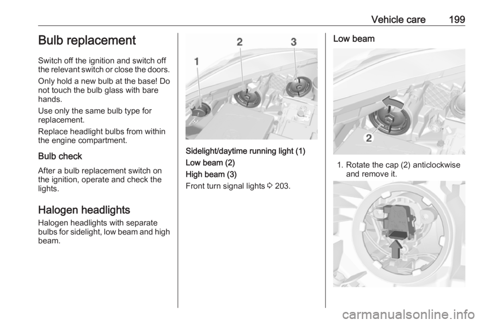
Halogen headlights Halogen headlights with separate
bulbs for sidelight, low beam and high
beam.
Sidelight/daytime running light (1)
Low beam (2)
High beam (3)
Front turn signal lights 3 203.
Low beam
1. Rotate the cap (2) anticlockwise
and remove it.
Page 202 of 269

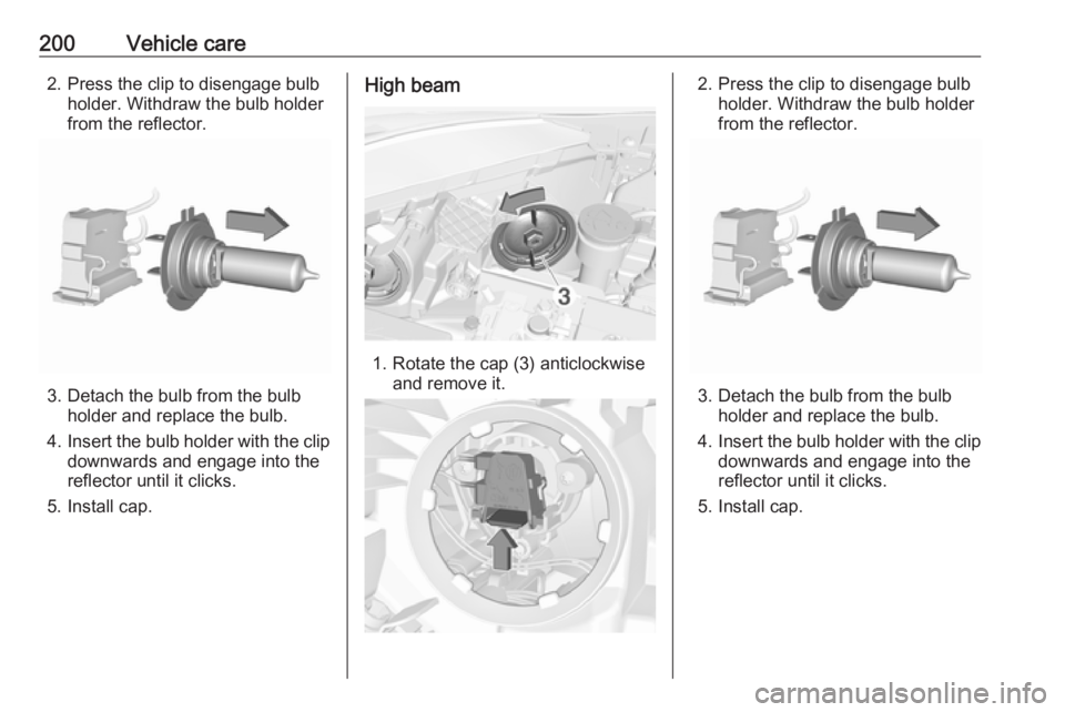
200Vehicle care2. Press the clip to disengage bulbholder. Withdraw the bulb holder
from the reflector.
3. Detach the bulb from the bulb holder and replace the bulb.
4. Insert the bulb holder with the clip
downwards and engage into the
reflector until it clicks.
5. Install cap.
High beam
1. Rotate the cap (3) anticlockwise and remove it.
2. Press the clip to disengage bulbholder. Withdraw the bulb holder
from the reflector.
3. Detach the bulb from the bulb holder and replace the bulb.
4. Insert the bulb holder with the clip
downwards and engage into the
reflector until it clicks.
5. Install cap.
Page 203 of 269

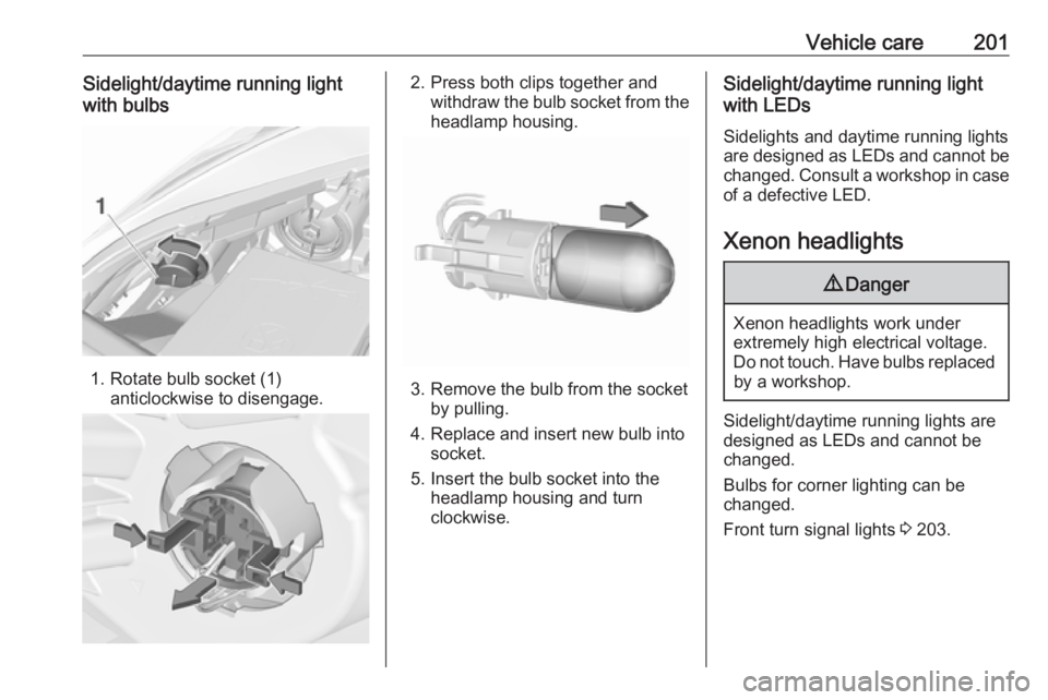
Vehicle care201Sidelight/daytime running light
with bulbs
1. Rotate bulb socket (1) anticlockwise to disengage.
2. Press both clips together andwithdraw the bulb socket from theheadlamp housing.
3. Remove the bulb from the socket by pulling.
4. Replace and insert new bulb into socket.
5. Insert the bulb socket into the headlamp housing and turn
clockwise.
Sidelight/daytime running light
with LEDs
Sidelights and daytime running lights
are designed as LEDs and cannot be
changed. Consult a workshop in case
of a defective LED.
Xenon headlights9 Danger
Xenon headlights work under
extremely high electrical voltage.
Do not touch. Have bulbs replaced by a workshop.
Sidelight/daytime running lights are
designed as LEDs and cannot be
changed.
Bulbs for corner lighting can be
changed.
Front turn signal lights 3 203.
Page 204 of 269

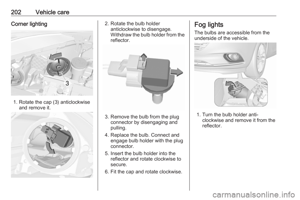
202Vehicle careCorner lighting
1. Rotate the cap (3) anticlockwiseand remove it.
2. Rotate the bulb holderanticlockwise to disengage.
Withdraw the bulb holder from the
reflector.
3. Remove the bulb from the plug connector by disengaging and
pulling.
4. Replace the bulb. Connect and engage bulb holder with the plug
connector.
5. Insert the bulb holder into the reflector and rotate clockwise to
secure.
6. Fit the cap and rotate clockwise.
Fog lights
The bulbs are accessible from the
underside of the vehicle.
1. Turn the bulb holder anti- clockwise and remove it from the
reflector.