remove OPEL CORSA E 2017.5 Service Manual
[x] Cancel search | Manufacturer: OPEL, Model Year: 2017.5, Model line: CORSA E, Model: OPEL CORSA E 2017.5Pages: 269, PDF Size: 7.97 MB
Page 205 of 269

Vehicle care203
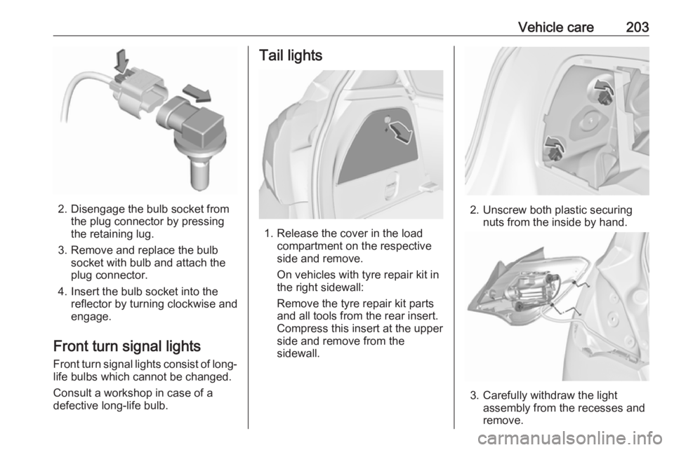
2. Disengage the bulb socket fromthe plug connector by pressing
the retaining lug.
3. Remove and replace the bulb socket with bulb and attach the
plug connector.
4. Insert the bulb socket into the reflector by turning clockwise and
engage.
Front turn signal lights
Front turn signal lights consist of long- life bulbs which cannot be changed.
Consult a workshop in case of a
defective long-life bulb.
Tail lights
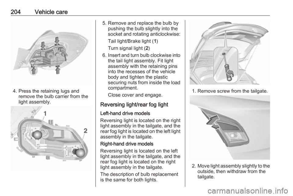
1. Release the cover in the load compartment on the respective
side and remove.
On vehicles with tyre repair kit in
the right sidewall:
Remove the tyre repair kit parts
and all tools from the rear insert.
Compress this insert at the upper
side and remove from the
sidewall.
2. Unscrew both plastic securing nuts from the inside by hand.
3. Carefully withdraw the light assembly from the recesses and
remove.
Page 206 of 269

204Vehicle care
4. Press the retaining lugs andremove the bulb carrier from the
light assembly.
5. Remove and replace the bulb by pushing the bulb slightly into thesocket and rotating anticlockwise:
Tail light/Brake light ( 1)
Turn signal light ( 2)
6. Insert and turn bulb clockwise into
the tail light assembly. Fit light
assembly with the retaining pins
into the recesses of the vehicle
body and tighten the plastic
securing nuts from inside the load
compartment.
Close cover and engage.
Reversing light/rear fog light Left-hand drive models
Reversing light is located on the right
light assembly in the tailgate, and the rear fog light is located on the left light
assembly in the tailgate.
Right-hand drive models
Reversing light is located on the left
light assembly in the tailgate, and the
rear fog light is located on the right
light assembly in the tailgate.
The description of bulb replacement
is the same for both lights.
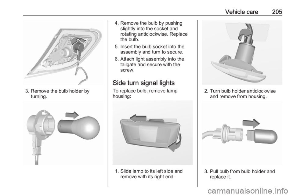
1. Remove screw from the tailgate.
2. Move light assembly slightly to the
outside, then withdraw from the
tailgate.
Page 207 of 269

Vehicle care205
3. Remove the bulb holder byturning.
4. Remove the bulb by pushingslightly into the socket and
rotating anticlockwise. Replace
the bulb.
5. Insert the bulb socket into the assembly and turn to secure.
6. Attach light assembly into the tailgate and secure with the
screw.
Side turn signal lights
To replace bulb, remove lamp
housing:
1. Slide lamp to its left side and remove with its right end.
2. Turn bulb holder anticlockwiseand remove from housing.
3. Pull bulb from bulb holder and replace it.
Page 208 of 269

206Vehicle care4. Insert bulb holder and turnclockwise.
5. Insert left end of the lamp, slide to
the left and insert right end.
Centre high-mounted brake light
Have LEDs replaced by a workshop.
Number plate light
1. Insert screwdriver in recess of the
cover, press to the side and
release spring.
2. Remove lamp downwards, taking care not to pull on the cable.
3. Remove bulb holder from lamp housing by turning anticlockwise.
4. Pull bulb from bulb holder andreplace it.
5. Insert bulb holder into lamp housing and turn clockwise.
6. Insert lamp into bumper and let engage.
Interior lights
Courtesy light, reading lights Have bulbs replaced by a workshop.
Load compartment light
Have bulbs replaced by a workshop.
Dome light
Have bulbs replaced by a workshop.
Instrument panel
illumination
Have bulbs replaced by a workshop.
Page 210 of 269

208Vehicle careEngine compartment fuse
box
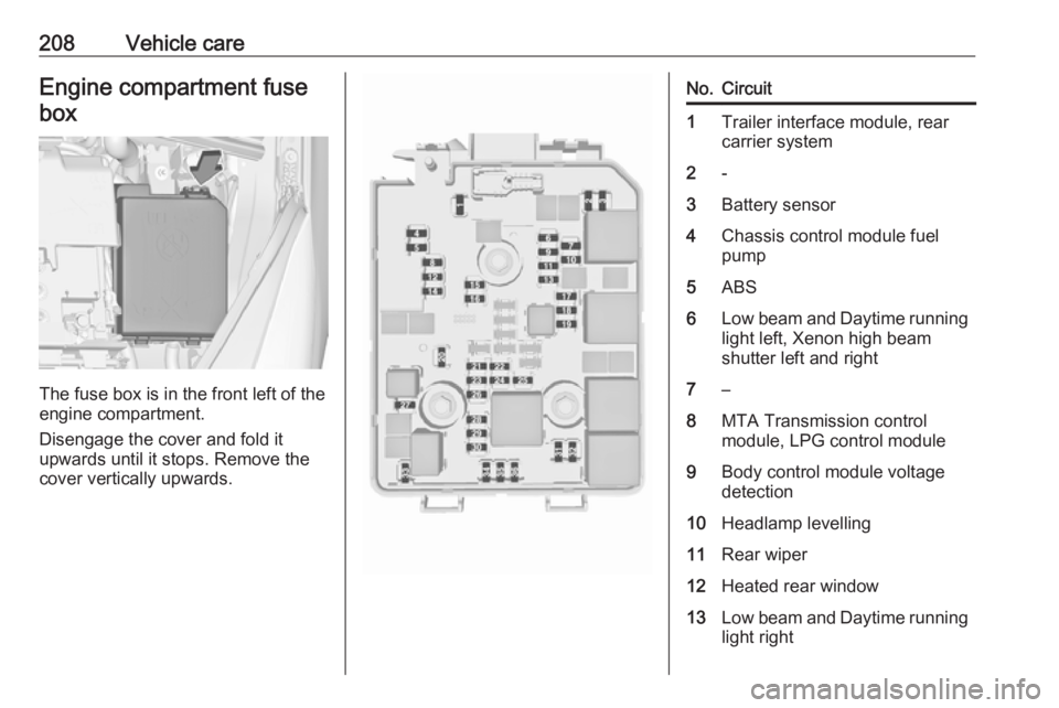
The fuse box is in the front left of the
engine compartment.
Disengage the cover and fold it
upwards until it stops. Remove the
cover vertically upwards.
No.Circuit1Trailer interface module, rear
carrier system2-3Battery sensor4Chassis control module fuel
pump5ABS6Low beam and Daytime running
light left, Xenon high beam
shutter left and right7–8MTA Transmission control
module, LPG control module9Body control module voltage
detection10Headlamp levelling11Rear wiper12Heated rear window13Low beam and Daytime running
light right
Page 222 of 269

220Vehicle careIf the wheel covers and tyres used are
not factory approved, the tyres must
not have a rim protection ridge.
Wheel covers must not impair brake
cooling.9 Warning
Use of unsuitable tyres or wheel
covers could lead to sudden
pressure loss and thereby
accidents.
Steel wheels: When using locking
wheel nuts, do not attach wheel
covers.
Tyre chains
Tyre chains are only permitted on the
front wheels.
Always use fine mesh chains that add no more than 10 mm to the tyre tread
and the inboard sides (including chain lock).
9 Warning
Damage may lead to tyre blowout.
Tyre chains are permitted on tyres of
size 175/70 R14, 185/70 R14,
185/65 R15, 205/45 R17.
Tyre chains are permitted on tyres of
size 195/55 R16 with rims of size
16 x 6 and 16 x 6.5, the latter only in combination with limited steering
angle. Seek the assistance of a
workshop.
Tyre chains are not permitted on tyres of size 215/45 R17 and 215/40 R18.
The use of tyre chains is not permitted on the temporary spare wheel.
Tyre repair kit Minor damage to the tyre tread can be
repaired with the tyre repair kit.
Do not remove foreign bodies from
the tyres.
Tyre damage exceeding 4 mm or that is at the tyre's side wall near the rim
cannot be repaired with the tyre repair kit.9 Warning
Do not drive faster than 80 km/h.
Do not use for a lengthy period.
Steering and handling may be
affected.
Page 223 of 269

Vehicle care221If you have a flat tyre:
Apply the parking brake and engage first gear, reverse gear or P.
The tyre repair kit is stowed in the load
compartment.
Depending on the equipment, the tyre repair kit is in a compartment in the
right sidewall or in a compartment
under the floor cover.
Vehicles with tyre repair kit under
the floor cover
1. Take the tyre repair kit from the compartment.
2. Remove the compressor.
3. Remove the electrical connection cable and air hose from the
stowage compartments on the
underside of the compressor.
4. Screw the compressor air hose to
the connection on the sealant
bottle.
5. Fit the sealant bottle into the retainer on the compressor.
Set the compressor near the tyre
in such a way that the sealant
bottle is upright.
6. Unscrew valve cap from defective
tyre.
7. Screw the filler hose to the tyre valve.
8. The switch on the compressor must be set to J.
Page 224 of 269

222Vehicle care9. Connect the compressor plug tothe power outlet or cigarette
lighter socket.
To avoid discharging the battery,
we recommend running the
engine.
10. Set the rocker switch on the compressor to I. The tyre is filled
with sealant.
11. The compressor pressure gauge briefly indicates up to six bar
whilst the sealant bottle is
emptying (approx. 30 seconds).
Then the pressure starts to drop.
12. All of the sealant is pumped into the tyre. Then the tyre is inflated.
13. The prescribed tyre pressureshould be obtained within ten
minutes.
Tyre pressure 3 253.
When the correct pressure is
obtained, switch off the
compressor.
If the prescribed tyre pressure is
not obtained within ten minutes,
remove the tyre repair kit. Move
the vehicle one tyre rotation.
Reattach the tyre repair kit and
continue the filling procedure for
ten minutes. If the prescribed tyre
pressure is still not obtained, the
tyre is too badly damaged. Seek
the assistance of a workshop.
Drain excess tyre pressure with
the button over the pressure indicator.
Do not run the compressor for
longer than ten minutes.
14. Detach the tyre repair kit. Push catch on bracket to remove
sealant bottle from bracket. Screw the tyre inflation hose to the freeconnection of the sealant bottle.
This prevents sealant from
escaping. Stow tyre repair kit in
load compartment.
15. Remove any excess sealant using a cloth.
16. Take the label indicating maximum permitted speed from
the sealant bottle and affix in the
driver's field of view.
17. Continue driving immediately so that sealant is evenly distributedin the tyre. After driving approx.
10 km (but no more than ten
minutes), stop and check tyre
pressure. Screw compressor air
hose directly onto tyre valve and
compressor when doing this.
Page 226 of 269

224Vehicle care
3. Position the sealant bottle on thebracket. Make sure that the bottle
does not fall.
4. Unscrew valve cap from defective
tyre.
5. Screw tyre inflation hose to valve.
6. Screw air hose onto compressor connection.
7. Switch on ignition. To avoid discharging the battery,
we recommend running the
engine.
8. Press on/off switch on the compressor. The tyre is filled withsealant.
9. The compressor pressure gauge briefly indicates up to six bar
whilst the sealant bottle is
emptying (approx. 30 seconds).
Then the pressure starts to drop.
10. All of the sealant is pumped into the tyre. Then the tyre is inflated.
11. The prescribed tyre pressure should be obtained within ten
minutes.
Tyre pressure 3 253.
When the correct pressure is
obtained, switch off the
compressor by pressing the on/off
switch again.
If the prescribed tyre pressure is
not obtained within ten minutes,
remove the tyre repair kit. Move
the vehicle one tyre rotation.
Reattach the tyre repair kit and
continue the filling procedure for ten minutes. If the prescribed tyre pressure is still not obtained, the
tyre is too badly damaged. Seek
the assistance of a workshop.
Release excess tyre pressure
using ].
Do not run the compressor for
longer than ten minutes.
12. Push catch on bracket to remove sealant bottle from bracket. Screw
the tyre inflation hose to the free
connection of the sealant bottle.
Page 227 of 269

Vehicle care225This prevents sealant from
escaping. Stow tyre repair kit in
load compartment.
13. Remove any excess sealant using a cloth.
14. Take the label indicating maximum permitted speed from
the sealant bottle and affix in the
driver's field of view.
15. Continue driving immediately so that sealant is evenly distributedin the tyre. After driving approx.
10 km (but no more than ten
minutes), stop and check tyre
pressure. Screw compressor air
hose directly onto tyre valve and
compressor when doing this.
If tyre pressure is more than 1.3 bar , set it to the correct value.
Repeat the procedure until there
is no more loss of pressure.
If the tyre pressure has fallen
below 1.3 bar, the vehicle must
not be used. Seek the assistance
of a workshop.
16. Stow away tyre repair kit in load compartment.General information
Note
The driving characteristics of the
repaired tyre are severely affected, therefore have this tyre replaced.
If unusual noise is heard or the
compressor becomes hot, turn
compressor off for at least
30 minutes.
The built-in safety valve opens at a
pressure of seven bar.
Note the expiry date of the kit. After
this date its sealing capability is no
longer guaranteed. Pay attention to
storage information on sealant
bottle.
Replace the used sealant bottle. Dispose of the bottle as prescribed
by applicable laws.
The compressor and sealant can be
used from approx. -30 °C.
The adapters supplied can be used
to pump up other items e.g.
footballs, air mattresses, inflatable
dinghies etc. They are located on the underside of the compressor. To
remove, screw on compressor air hose and withdraw adapter.Wheel changing
Make the following preparations and
observe the following information:
● Park the vehicle on a level, firm and non-skid surface. The front
wheels must be in the straight- ahead position.
● Apply the parking brake and engage first gear, reverse gear or
P .
● Never change more than one wheel at once.
● Use the jack only to change wheels in case of puncture, not
for seasonal winter or summer
tyre change.
● The jack is maintenance-free.
● If the ground on which the vehicle
is standing is soft, a solid board
(max. 1 cm thick) should be
placed under the jack.
● Take heavy objects out of the vehicle before jacking up.
● No people or animals may be in the vehicle when it is jacked-up.
● Never crawl under a jacked-up vehicle.