Back OPEL FRONTERA 1998 Workshop Manual
[x] Cancel search | Manufacturer: OPEL, Model Year: 1998, Model line: FRONTERA, Model: OPEL FRONTERA 1998Pages: 6000, PDF Size: 97 MB
Page 1470 of 6000
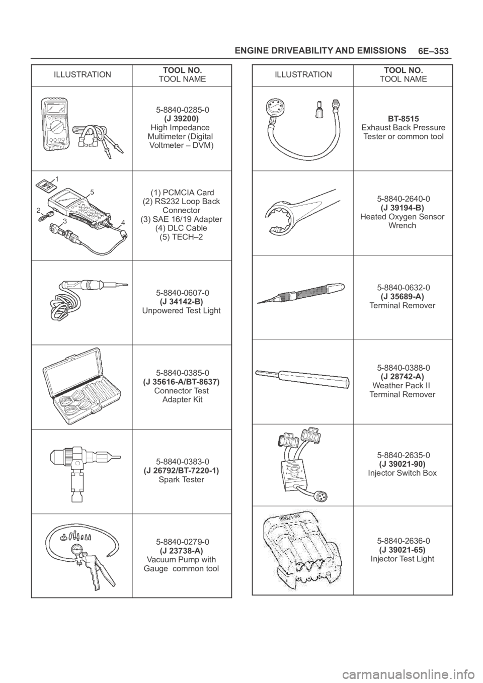
6E–353 ENGINE DRIVEABILITY AND EMISSIONS
ILLUSTRATIONTOOL NO.
TOOL NAME
5-8840-0285-0
(J 39200)
High Impedance
Multimeter (Digital
Vo l t m e t e r – D V M )
(1) PCMCIA Card
(2) RS232 Loop Back
Connector
(3) SAE 16/19 Adapter
(4) DLC Cable
(5) TECH–2
5-8840-0607-0
(J 34142-B)
Unpowered Test Light
5-8840-0385-0
(J 35616-A/BT-8637)
Connector Test
Adapter Kit
5-8840-0383-0
(J 26792/BT-7220-1)
Spark Tester
5-8840-0279-0
(J 23738-A)
Vacuum Pump with
Gauge common tool
ILLUSTRATIONTOOL NO.
TOOL NAME
BT-8515
Exhaust Back Pressure
Tester or common tool
5-8840-2640-0
(J 39194-B)
Heated Oxygen Sensor
Wrench
5-8840-0632-0
(J 35689-A)
Terminal Remover
5-8840-0388-0
(J 28742-A)
Weather Pack II
Terminal Remover
5-8840-2635-0
(J 39021-90)
Injector Switch Box
5-8840-2636-0
(J 39021-65)
Injector Test Light
Page 1746 of 6000

ENGINE MECHANICAL 6A – 13
VALVE CLEARANCE ADJUSTMENT
1. Install 2.80 mm valve adjuster (shim) first when
reassembling the engine.
Thickness mark faces down.
2. Measure the valve clearance after installing cam
carrier assy with camshafts.
3. Change the adjuster using a special tool when the
clearance is out of tolerance.
Valve Clearance Adjusting Tool: 5-8840-2590-0
VALVE CLEARANCE (When cold condition)
Inlet 0.15 ± 0.05 mm
Exh 0.25 ± 0.05 mm
COMPRESSION PRESSURE
MEASUREMENT
1. Start the engine and allow it to idle until the coolant
temperature reaches 70 – 80°C (158 – 176°F).
2. Remove the following parts.
Glow plugs
Fuel cut solenoid connector
QOS (Quick-On Start System) fuse in the fuse
box.
3. Set the adapter and compression gauge to the No.
1 cylinder glow plug hole.
Compression Gauge
(with Adapter): 5-8840-2008-0
4. Turn the engine over with the starter motor and take
the compression gauge reading.
Compression Pressure at 200 rpm
Standard: 3040 kPa (31 kg/cm
2/441 psi)
Limit: 2160 kPa (22 kg/cm
2/313 psi)
5. Repeat the procedure (Steps 3 and 4) for the
remaining cylinders.
QUICK-ON START 4 SYSTEM
Quick-On Start System Inspection Procedure
1. Disconnect the ECT-sensor connection around the
thermostat outlet pipe.
2. Turn the starter switch to the “ON” position.
If the Quick-On Start 4 System is operating
properly, the glow relay will make a clicking sound
within seven seconds after the starter switch is
turned on.
3. Measure the glow plug terminal voltage with a
circuit tester immediately after turning the starter
switch to the “ON” position.
Glow Plug Terminal Voltage: approx. 12V
NOTE: Electrical power to the quick-on start system will
be cut after the starter has remained in the “ON”
position for twenty seconds.
Turn the starter switch to the “OFF” position and back
to the “ON” position.
This will reset the Quick-On Start 4 System.
014RW150
Page 1798 of 6000

ENGINE MECHANICAL 6A – 65
Valve Seat Insert Installation
1. Carefully place the attachment (1) (having a smaller
outside diameter than the valve seat insert) on the
valve seat insert (2).
Legend
(1) Attachment
(2) Valve Seat Insert
(3) Bench Press
NOTE: The smooth side of the attachment must contact
the valve seat insert.
2. Use a bench press (3) to gradually apply pressure
to the attachment and press the valve seat insert
into place.
Note: Do not apply an excessive amount of pressure
with the bench press. Damage to the valve seat insert
will result.
Valve Seat Insert Correction
1. Remove the carbon from the valve seat insert
surface.
2. Use a valve cutter (15°, 45° and 75° blades) to
minimize scratches and other rough areas. This will
bring the contact width back to the standard value.
Remove only the scratches and rough areas. Do
not cut away too much. Take care not to cut away
unblemished areas of the valve seat surface.
Valve Seat Angle: 45°NOTE: Use an adjustable valve cutter pilot.
Do not allow the valve cutter pilot to wobble inside the
valve guide.
3. Apply abrasive compound to the valve seat insert
surface.
4. Insert the valve into the valve guide.
5. Turn the valve while tapping it to fit the valve seat
insert.
6. Check that the valve contract width is correct.
7. Check that the valve seat insert surface is in
contact with the entire circumference of the valve.
3
2 1
012RW055
150
90
30
012RW056
014RS014
Page 1821 of 6000

6A – 88 ENGINE MECHANICAL
2. Measure the inside diameter of the connecting rod
small end. If the clearance between the small end
and pin does not conform to the specified value, the
connecting rod or bushing and pin must be
replaced.
Standard: 0.008 – 0.020 mm (0.0003 – 0.0008 in )
Limit: 0.05 mm (0.0020 in)
3. Insert the piston pin into the piston and rotate it. If
the pin rotates smoothly with no backlash, the
clearance is normal. If there is backlash or
roughness, measure the clearance. If the clearance
exceeds the specified limit, the piston and the
piston pin must be replaced.
Standard: 0.005 – 0.018 mm (0.0002 – 0.0007 in )
Limit: 0.04 mm (0.0016 in)
Bushing replacement
Removal: Use a suitable bar and bench press or
hammer
Installation: Align the bushing with a connecting rod
oil port. After installing a new bushing,
finish the bushing bore with a pin hole
grinder.Connecting rods
1. Check the connecting rod alignment with a
connecting rod aligner.
If either the bend or the twist exceeds the specified
limit, the connecting rod must be replaced.
Bend per 100 mm (3.937 in)
Standard: 0.08 mm (0.0031 in) or less
Limit: 0.20 mm (0.0079 in)
Twist per 100 mm (3.937 in)
Standard: 0.05 mm (0.0020 in) or less
Limit: 0.15 mm (0.0059 in)
2. Measure the connecting rod thrust clearance.
Use a feeler gauge to measure the thrust clearance
at the big end of the connecting rod.
If the clearance exceeds the specified limit, the
connecting rod must be replaced.
Standard: 0.230 mm (0.0091 in)
Limit: 0.350 mm (0.0138 in)
012RW074
012RW123
012RW001
Page 1912 of 6000
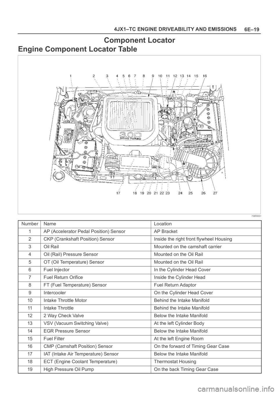
6E–19 4JX1–TC ENGINE DRIVEABILITY AND EMISSIONS
Component Locator
Engine Component Locator Table
F06RW051
NumberNameLocation
1AP (Accelerator Pedal Position) SensorAP Bracket
2CKP (Crankshaft Position) SensorInside the right front flywheel Housing
3Oil RailMounted on the camshaft carrier
4Oil (Rail) Pressure SensorMounted on the Oil Rail
5OT (Oil Temperature) SensorMounted on the Oil Rail
6Fuel InjectorIn the Cylinder Head Cover
7Fuel Return OrificeInside the Cylinder Head
8FT (Fuel Temperature) SensorFuel Return Adaptor
9IntercoolerOn the Cylinder Head Cover
10Intake Throttle MotorBehind the Intake Manifold
11Intake ThrottleBehind the Intake Manifold
122 Way Check ValveBelow the Intake Manifold
13VSV (Vacuum Switching Valve)At the left Cylinder Body
14EGR Pressure SensorBelow the Intake Manifold
15Fuel FilterAt the left Engine Room
16CMP (Camshaft Position) SensorOn the forward of Timing Gear Case
17IAT (Intake Air Temperature) SensorBelow the Intake Manifold
18ECT (Engine Coolant Temperature)Thermostat Housing
19High Pressure Oil PumpOn the back Timing Gear Case
Page 1923 of 6000
6E–30
4JX1–TC ENGINE DRIVEABILITY AND EMISSIONS
Getting Started
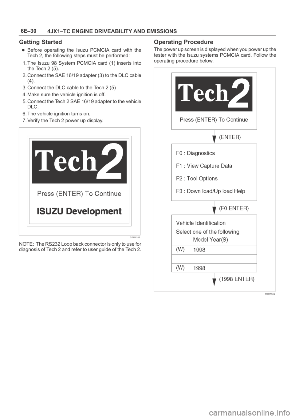
Before operating the Isuzu PCMCIA card with the
Tech 2, the following steps must be performed:
1. The Isuzu 98 System PCMCIA card (1) inserts into
the Tech 2 (5).
2. Connect the SAE 16/19 adapter (3) to the DLC cable
(4).
3. Connect the DLC cable to the Tech 2 (5)
4. Make sure the vehicle ignition is off.
5. Connect the Tech 2 SAE 16/19 adapter to the vehicle
DLC.
6. The vehicle ignition turns on.
7. Verify the Tech 2 power up display.
012RW105
NOTE: The RS232 Loop back connector is only to use for
diagnosis of Tech 2 and refer to user guide of the Tech 2.
Operating Procedure
The power up screen is displayed when you power up the
tester with the Isuzu systems PCMCIA card. Follow the
operating procedure below.
060RW014
Page 1932 of 6000
6E–39 4JX1–TC ENGINE DRIVEABILITY AND EMISSIONS
Engine Control Module ECM
Diagnosis
To read and clear diagnostic trouble codes, use a Tech 2.
IMPORTANT:Use of a Tech 2 is recommended to clear
diagnostic trouble codes from the ECM memory.
Diagnostic trouble codes can also be cleared by turning
the ignition “OFF” and disconnecting the battery power
from the ECM for 30 seconds. Turning off the ignition and
disconnecting the battery power from the ECM will cause
all diagnostic information in the ECM memory to be
cleared. Therefore, all the diagnostic tests will have to be
re-run.
Since the ECM can have a failure which may affect only
one circuit, following the diagnostic procedures in this
section will determine which circuit has a problem and
where it is.
If a diagnostic chart indicates that the ECM connections
or the ECM is the cause of a problem, and the ECM is
replaced, but this does not correct the problem, one of the
following may be the reason:
There is a problem with the ECM terminal
connections. The terminals may have to be removed
from the connector in order to check them properly.
The problem is intermittent. This means that the
problem is not present at the time the system is being
checked. In this case, refer to the
Symptoms portion
of the manual and make a careful physical inspection
of all components and wiring associated with the
affected system.
There is a shorted solenoid, relay coil, or harness.
Solenoids and relays are turned “ON” and “OFF” by
the ECM using internal electronic switches called
drivers. A shorted solenoid, relay coil, or harness will
not damage the ECM but will cause the solenoid or
relay to be inoperative.
Multiple ECM Information Sensor
DTCS Set
Circuit Description
The Engine Control Module ECM monitors various
sensors to determine the engine operating conditions.
The ECM controls fuel delivery, spark advance,
transmission operation, and emission control device
operation based on the sensor inputs.
The ECM provides a sensor ground to all of the sensors.
The ECM applies 5 volts through a pull-up resistor, and
determines the status of the following sensors by
monitoring the voltage present between the 5-volt supply
and the resistor:
The fuel temperature (FT) sensor
The engine coolant temperature (ECT) sensor
The Intake air temperature (IAT) sensor
The ECM provides the following sensors with a 5-volt
reference and a sensor ground signal:
The Intake throttle position sensor
The manifold absolute pressure sensor
The rail pressure sensor
The accelerator position sensor
The oil temperature sensor
The camshaft position sensor
The crankshaft position sensor
The EGR pressure sensor
The ECM monitors the signals from these sensors in
order to determine their operating status.
Diagnostic Aids
IMPORTANT:Be sure to inspect ECM and engine
grounds for being secure and clean.
A short to voltage in one of the sensor input circuits may
cause one or more of the following DTCs to be set:
P0337
P0342
P1193
P1404
P1405
P1488
IMPORTANT:If a sensor input circuit has been shorted
to voltage, ensure that the sensor is not damaged. A
damaged sensor will continue to indicate a high or low
voltage after the affected circuit has been repaired. If the
sensor has been damaged, replace it.
An open in the sensor ground circuit between the ECM
and the splice will cause one or more of the following
DTCs to be set:
P0337
P0342
P0117
A short to ground in the 5-volt reference A or B circuit will
cause one or more of the following DTCs to be set:
P0112
P0117
P0182
P0197
An open in the 5-volt reference circuit A, between the
ECM and the splice will cause one or more of the following
DTCs to be set:
P0107
P0405
P1194
P0122
An open in the 5-volt reference circuit B, between the
ECM and the splice will cause one or more of the following
DTCs to be set:
P1485
Check for the following conditions:
Poor connection at ECM. Inspect the harness
connectors for backed-out terminals, improper
mating, broken locks, improperly formed or damage
terminals, and a poor terminal-to-wire connection.
Damaged harness. Inspect the wiring harness for
damage. If the harness is not damaged, observe an
affected sensor’s displayed value on the Tech 2 with
the ignition “ON” and the engine “OFF” while you
move the connectors and the wiring harnesses
related to the following sensors:
ECT Sensor
Page 1949 of 6000
6E–56
4JX1–TC ENGINE DRIVEABILITY AND EMISSIONS
Diagnostic Trouble Code (DTC) P0107 (Flash DTC 34)
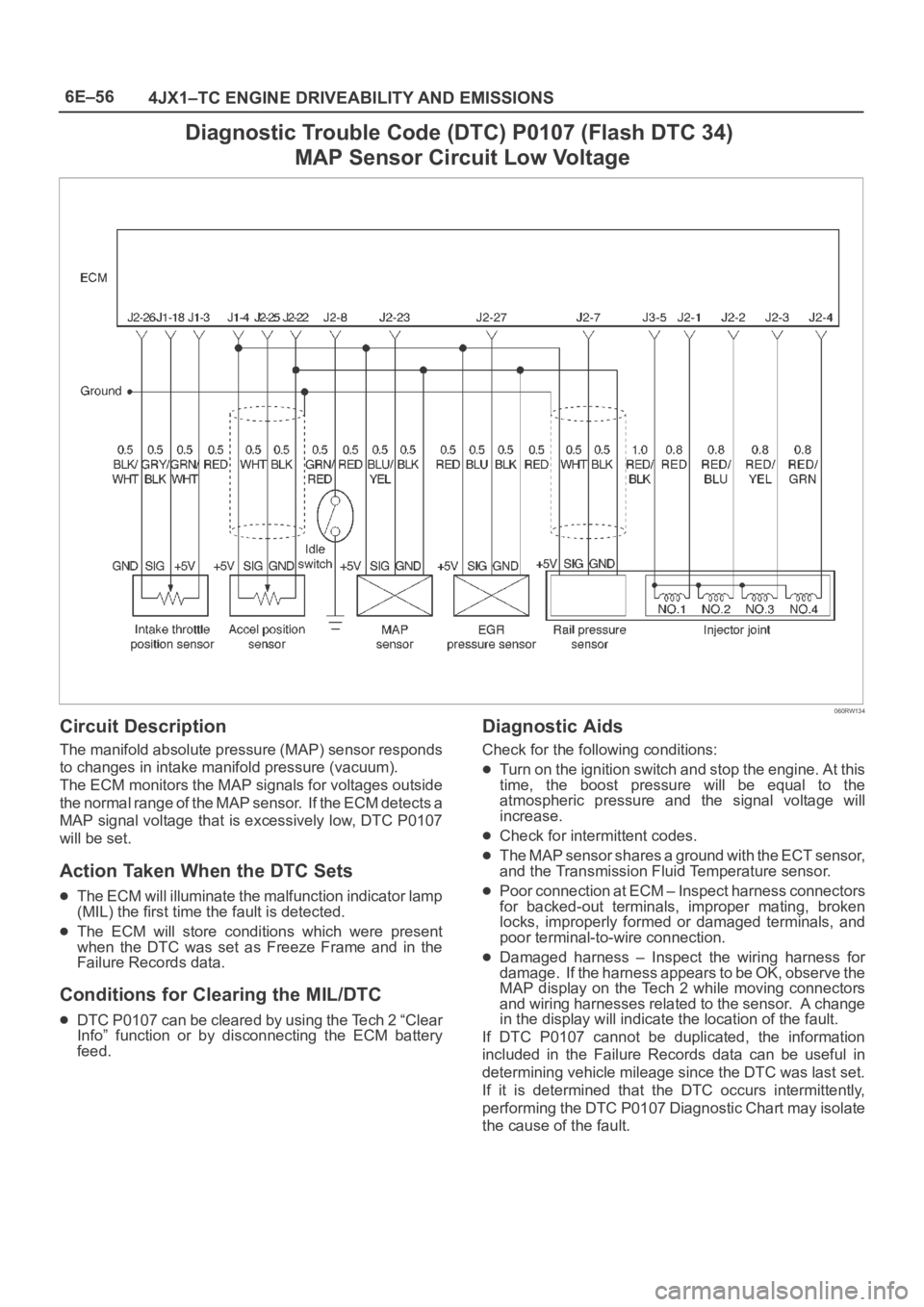
MAP Sensor Circuit Low Voltage
060RW134
Circuit Description
The manifold absolute pressure (MAP) sensor responds
to changes in intake manifold pressure (vacuum).
The ECM monitors the MAP signals for voltages outside
the normal range of the MAP sensor. If the ECM detects a
MAP signal voltage that is excessively low, DTC P0107
will be set.
Action Taken When the DTC Sets
The ECM will illuminate the malfunction indicator lamp
(MIL) the first time the fault is detected.
The ECM will store conditions which were present
when the DTC was set as Freeze Frame and in the
Failure Records data.
Conditions for Clearing the MIL/DTC
DTC P0107 can be cleared by using the Tech 2 “Clear
Info” function or by disconnecting the ECM battery
feed.
Diagnostic Aids
Check for the following conditions:
Turn on the ignition switch and stop the engine. At this
time, the boost pressure will be equal to the
atmospheric pressure and the signal voltage will
increase.
Check for intermittent codes.
The MAP sensor shares a ground with the ECT sensor,
and the Transmission Fluid Temperature sensor.
Poor connection at ECM – Inspect harness connectors
for backed-out terminals, improper mating, broken
locks, improperly formed or damaged terminals, and
poor terminal-to-wire connection.
Damaged harness – Inspect the wiring harness for
damage. If the harness appears to be OK, observe the
MAP display on the Tech 2 while moving connectors
and wiring harnesses related to the sensor. A change
in the display will indicate the location of the fault.
If DTC P0107 cannot be duplicated, the information
included in the Failure Records data can be useful in
determining vehicle mileage since the DTC was last set.
If it is determined that the DTC occurs intermittently,
performing the DTC P0107 Diagnostic Chart may isolate
the cause of the fault.
Page 1951 of 6000
6E–58
4JX1–TC ENGINE DRIVEABILITY AND EMISSIONS
Diagnostic Trouble Code (DTC) P0108 (Flash DTC 34)
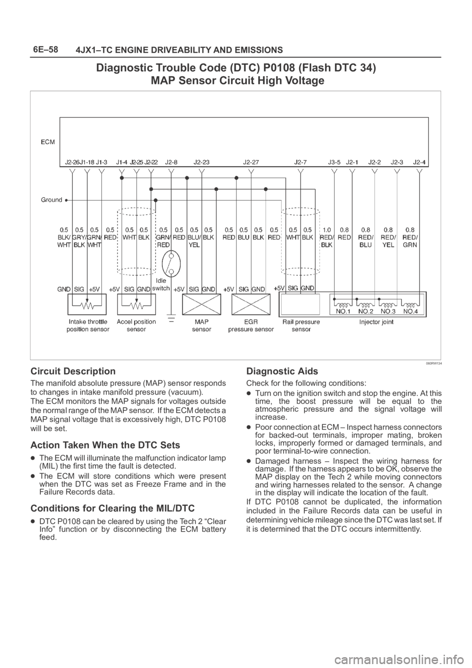
MAP Sensor Circuit High Voltage
060RW134
Circuit Description
The manifold absolute pressure (MAP) sensor responds
to changes in intake manifold pressure (vacuum).
The ECM monitors the MAP signals for voltages outside
the normal range of the MAP sensor. If the ECM detects a
MAP signal voltage that is excessively high, DTC P0108
will be set.
Action Taken When the DTC Sets
The ECM will illuminate the malfunction indicator lamp
(MIL) the first time the fault is detected.
The ECM will store conditions which were present
when the DTC was set as Freeze Frame and in the
Failure Records data.
Conditions for Clearing the MIL/DTC
DTC P0108 can be cleared by using the Tech 2 “Clear
Info” function or by disconnecting the ECM battery
feed.
Diagnostic Aids
Check for the following conditions:
Turn on the ignition switch and stop the engine. At this
time, the boost pressure will be equal to the
atmospheric pressure and the signal voltage will
increase.
Poor connection at ECM – Inspect harness connectors
for backed-out terminals, improper mating, broken
locks, improperly formed or damaged terminals, and
poor terminal-to-wire connection.
Damaged harness – Inspect the wiring harness for
damage. If the harness appears to be OK, observe the
MAP display on the Tech 2 while moving connectors
and wiring harnesses related to the sensor. A change
in the display will indicate the location of the fault.
If DTC P0108 cannot be duplicated, the information
included in the Failure Records data can be useful in
determining vehicle mileage since the DTC was last set. If
it is determined that the DTC occurs intermittently.
Page 1953 of 6000
6E–60
4JX1–TC ENGINE DRIVEABILITY AND EMISSIONS
Diagnostic Trouble Code (DTC) P0112 (Flash DTC 23)
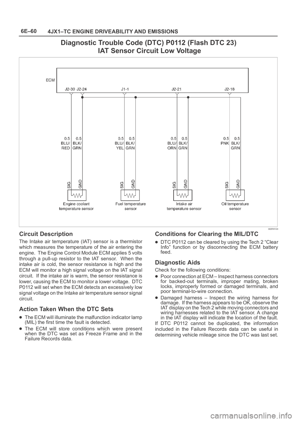
IAT Sensor Circuit Low Voltage
060RW129
Circuit Description
The Intake air temperature (IAT) sensor is a thermistor
which measures the temperature of the air entering the
engine. The Engine Control Module ECM applies 5 volts
through a pull-up resistor to the IAT sensor. When the
intake air is cold, the sensor resistance is high and the
ECM will monitor a high signal voltage on the IAT signal
circuit. If the intake air is warm, the sensor resistance is
lower, causing the ECM to monitor a lower voltage. DTC
P0112 will set when the ECM detects an excessively low
signal voltage on the Intake air temperature sensor signal
circuit.
Action Taken When the DTC Sets
The ECM will illuminate the malfunction indicator lamp
(MIL) the first time the fault is detected.
The ECM will store conditions which were present
when the DTC was set as Freeze Frame and in the
Failure Records data.
Conditions for Clearing the MIL/DTC
DTC P0112 can be cleared by using the Tech 2 “Clear
Info” function or by disconnecting the ECM battery
feed.
Diagnostic Aids
Check for the following conditions:
Poor connection at ECM – Inspect harness connectors
for backed-out terminals, improper mating, broken
locks, improperly formed or damaged terminals, and
poor terminal-to-wire connection.
Damaged harness – Inspect the wiring harness for
damage. If the harness appears to be OK, observe the
IAT display on the Tech 2 while moving connectors and
wiring harnesses related to the IAT sensor. A change
in the IAT display will indicate the location of the fault.
If DTC P0112 cannot be duplicated, the information
included in the Failure Records data can be useful in
determining vehicle mileage since the DTC was last set.