low oil pressure OPEL FRONTERA 1998 Workshop Manual
[x] Cancel search | Manufacturer: OPEL, Model Year: 1998, Model line: FRONTERA, Model: OPEL FRONTERA 1998Pages: 6000, PDF Size: 97 MB
Page 5335 of 6000

6A – 62 ENGINE MECHANICAL
INSTALLATION
1. Valve stem seal
1) Use the special tool to install the stem seal to the
valve guide.
Stem Seal Installer: 5-8840-2033-0
2. Valve spring.
1) Install the lower valve seat spring, valve spring,
then the upper valve spring seat.
2) Use valve spring compressor to compress the
spring then install the split collar.
Valve spring compressor: 5-8840-2441-0
NOTE: Make sure the split collar installs completely.
3. Install cylinder head assembly.
Refer to “Cylinder Head” in this manual.
4. Install the camshaft carrier with camshaft.
Refer to “Camshaft” in this manual.
5. Install oil rail assembly.
Refer to “Oil rail and injector” in this manual.
6. Install injector assembly.
Refer to “Oil rail and injector” in this manual.
7. Install the injector harness assembly.
Refer to “Injector” in this manual.
8. Reconnect harness connecter to oil pressure
sensor and oil temperature sensor on the oil rail.
9. Reconnect Injector harness connecter to injector.
Refer to “Injector” in this manual.
10. Install cylinder head cover with gasket.
Refer to “Cylinder Head Cover” in this manual.
11. Install glow plug with specified torque.
Torque: 15 Nꞏm (1.5 kgꞏm / 10.8 lb ft)
12. Install the intake manifold assembly.
Refer to “Intake Manifold” in this manual.
13. Install the fuel pipe.14. Install the water pipe between the cylinder head
and water pump.
Torque: 20 Nꞏm (2.0 kꞏm / 14.5 lb ft)
15. Install the front plate.
16. Install the camshaft pulley.
Refer to “Timing Gear” in this manual.
17. Install timing belt and set the tensioner.
Refer to “Timing Belt” in this manual.
18. Install CMP sensor bracket.
Torque: 20 Nꞏm (2.0 kgꞏm / 14.5 lb ft)
19. Install timing belt cover.
Torque: 9 Nꞏm (0.9 kgꞏm / 6.5 lb ft)
20. Fill the oil rail with engine oil then immediately
install the high pressure oil pipe with the specified
torque.
Torque: 80 Nꞏm (8.1 kgꞏm / 57.9 lb ft)
21. Install the noise insulator cover.
22. Reconnect hose between thermostat and radiator.
23. Install turbocharger assembly.
Refer to “Turbocharger” in this manual.
24. Install water hose and oil pipe for turbocharger.
Refer to “Turbocharger” in this manual.
25. Install the valve assembly and install heat protector.
26. Install generator and set the fan belts.
27. Install A/C compressor bracket, compressor
assembly and set drive belt.
28. Reconnect harness connector around cylinder
head.
29. Reconnect vacuum hose to EGR valve.
30. Reconnect PCV hose.
31. Install oil level gauge guide assembly.
32. Install intercooler assembly.
Refer to “Intercooler” in this manual.
33. Install the air duct assembly.
34. Fill engine coolant.
35. Connect battery ground cable.
014RW042
Page 5337 of 6000

6A – 64 ENGINE MECHANICAL
3. Determine the thickness of the adjuster as follows.
1) Measure the thickness of the removed adjuster
with a micrometer.
2) Calculate the thickness of a new adjuster.
Calculation
TA: Thickness of new adjuster
M: Valve clearance measurement.
TO: Thickness of the removed adjuster
For intake side: TA=TO+(M–0.15) mm
For exhaust side: TA=TO+(M–0.25) mm
Select a new adjuster whose thickness is as
close to the estimated value as possible.
4. Install oil rail and tighten it temporarily.
5. Install injector assembly.
NOTE:
1) Do not forget to insert the O-ring between injector
and oil rail.
2) Install the injector to the same position as before
removal.
6. Install the injector fixing bolts and temporarily
tighten.
7. Install the injector clamp and tighten temporarily.
8. Tighten injector fixing bolts to the specified torque.
Torque: 6.5 Nꞏm (0.7 kgꞏm / 5.1 lb ft)
9. Tighten injector clamp nut to the specified torque
with special method.
Torque: loosen one turn and tighten again to
specified torque.
Torque: 25 Nꞏm (2.4 kgꞏm / 17.4 lb ft)
10. Tighten oil rail to the specified torque.
Torque: 20 Nꞏm (2.0 kgꞏm / 14.5 lb ft)
11. Install injector harness and reconnect connector.
12. Install cylinder head cover.
Refer to”Cylinder Head” in this manual.
13. Fill with about 300cc of engine oil at the high
pressure oil pipe installation port on the oil rail using
an oil filler.
If assembled without filling the oil rail with oil, the
time for engine starting will be longer.
14. Immediately install high pressure oil pipe to tighten
with specified torque.
Torque: 80 Nꞏm (8.1 kgꞏm / 57.9 lb ft)
15. Install cylinder head noise insulator cover.
Refer to “Cylinder Head” in this manual.
Page 5338 of 6000

ENGINE MECHANICAL 6A – 65
OIL RAIL AND INJECTOR
REMOVAL
Prior to removal, be sure to confirm and record the
group code of the injector installed using Tech2.
1. Disconnect battery ground cable.
2. Remove air cleaner cover and air duct.
3. Remove intercooler.
Refer to “Intercooler” in this manual.
4. Remove PCV hose and pipe.
5. Remove cylinder head noise insulator cover.
6. Remove high pressure oil pipe.
CAUTION:
1) Sleeve nut should be loosened with cloth tied
around it to prevent oil from spurting due to the
remaining pressure.
2) The high pressure pipe should be disconnected
with a cloth tied around the intake manifold
glow plug to prevent oil from flowing out of the
oil rail.7. Loosen eye bolt of fuel pipe at fuel pump side.
NOTE: Cloth should be put around the loosened eye
bolt to prevent fuel from flowing out.
8. Remove fuel return hose at chassis side.
9. Remove PCV hose to cylinder head cover.
10. Remove cylinder head cover.
11. Drain the oil from oil rail assembly.
12. Record the identification marking of injector for
each cylinder which is indicated on the upper
portion of injector.
There are nine kinds of identification marking
available, one alphabet letter and one numeral
letter.
In case three kinds of markings are given, one
alphabet letter (sometimes printed) and one
numeral letter, top priority is given to the one
alphabet letter and one numeral letter.
1
6
27
3
5
4
012RW102-1
Legend
(1) Injector Clamp
(2) Injector Assembly
(3) Oil Rail Assembly(4) Camshaft Bracket
(5) Camshaft
(6) O-Ring
7) Drain Plug
Page 5339 of 6000

6A – 66 ENGINE MECHANICAL
(For example)
If you find identification marking “A”, “RA” and “2”
on the injector, you can use injector grade “A”. (The
“RA” is sometimes printed, but can be ignored)
Legend
(1) Part Number
(2) Two Alphabet Letter
(3) Serial Number
(4) Bar Code
(5) One Alphabet Letter
(6) One Numeral Letter
13. Remove harness connector from each injector.
14. Loosen nuts and bolts for oil rail.
15. Remove injector fixing bolts.
16. Remove injector clamp.
17. Remove injector assembly.
NOTE: Do not drop O-ring INSTALLATION
1. Install oil rail, tighten temporarily
2. Install injector assembly.
NOTE: Do not forget to install between injector and oil
rail.
3. Install injector fixing bolts, tighten temporarily.
4. Install injector clamp, tighten nut temporarily.
5. Tighten injector bolts to the specified torque.
Torque: 6.5 Nꞏm (0.7 kgꞏm / 5.1 lb ft)
6. Tighten injector clamp nut to the specified torque
with special method.
Torque: 30 Nꞏm (3.1 kgꞏm / 22 lb ft) then loose a
time again tighten as following torque.
Torque: 25 Nꞏm (2.4 kgꞏm / 17.4 lb ft)
7. Tighten oil rail to the specified torque.
Torque: 20 Nꞏm (2.0 kgꞏm / 14.5 lb ft)
8. Install injector harness assembly, reconnect
harness connecter to injector.
9. Record the identification marking of injector for
each cylinder that is indicated on the upper portion
of injector.
Legend
(1) Part Number
(2) Two Alphabet Letter
(3) Serial Number
(4) Bar Code
(5) One Alphabet Letter
(6) One Numeral Letter
10. Install cylinder head assembly.
Refer to “Cylinder Head” in this manual.
11. Fill with about 300cc of engine oil from the high
pressure oil pipe at the high pressure oil pipe
installation port on the oil rail using an oil filler.
If assembled without filling the oil rail with oil, the
time for engine starting will be longer.
1
4
3
265
055RW021-1
1
4
3
265
055RW021-1
Identification
One Alphabet One Numeral
Marking
Letter Letter
Grade
A1
AA2
A3
B1
BB2
B3
C1
CC2
C3
Page 5358 of 6000
ENGINE MECHANICAL 6A – 85
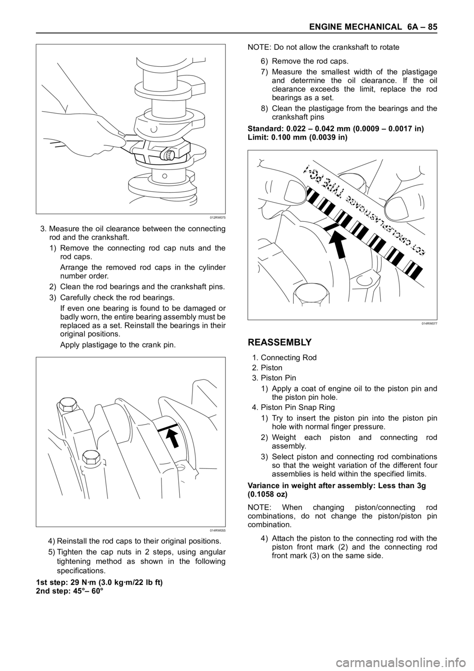
3. Measure the oil clearance between the connecting
rod and the crankshaft.
1) Remove the connecting rod cap nuts and the
rod caps.
Arrange the removed rod caps in the cylinder
number order.
2) Clean the rod bearings and the crankshaft pins.
3) Carefully check the rod bearings.
If even one bearing is found to be damaged or
badly worn, the entire bearing assembly must be
replaced as a set. Reinstall the bearings in their
original positions.
Apply plastigage to the crank pin.
4) Reinstall the rod caps to their original positions.
5) Tighten the cap nuts in 2 steps, using angular
tightening method as shown in the following
specifications.
1st step: 29 Nꞏm (3.0 kgꞏm/22 lb ft)
2nd step: 45°– 60°NOTE: Do not allow the crankshaft to rotate
6) Remove the rod caps.
7) Measure the smallest width of the plastigage
and determine the oil clearance. If the oil
clearance exceeds the limit, replace the rod
bearings as a set.
8) Clean the plastigage from the bearings and the
crankshaft pins
Standard: 0.022 – 0.042 mm (0.0009 – 0.0017 in)
Limit: 0.100 mm (0.0039 in)
REASSEMBLY
1. Connecting Rod
2. Piston
3. Piston Pin
1) Apply a coat of engine oil to the piston pin and
the piston pin hole.
4. Piston Pin Snap Ring
1) Try to insert the piston pin into the piston pin
hole with normal finger pressure.
2) Weight each piston and connecting rod
assembly.
3) Select piston and connecting rod combinations
so that the weight variation of the different four
assemblies is held within the specified limits.
Variance in weight after assembly: Less than 3g
(0.1058 oz)
NOTE: When changing piston/connecting rod
combinations, do not change the piston/piston pin
combination.
4) Attach the piston to the connecting rod with the
piston front mark (2) and the connecting rod
front mark (3) on the same side.
014RW055
012RW075
014RW077
Page 5374 of 6000

ENGINE COOLING 6B – 5
ENGINE COOLANT CHANGE
PROCEDURE
1. To change engine coolant, make sure that the
engine is cool.
WARNING:
When the coolant is heated to a high temperature,
be sure not to loosen or remove the radiator cap.
Otherwise you might get scalded by hot vapor or
boiling water. To open the radiator cap, put a piece
of thick cloth on the cap and loosen the cap slowly
to reduce the pressure once the coolant has
become cooler.
2. Open radiator cap and drain the cooling system by
loosening the drain valve on the radiator and on the
cylinder body.
NOTE: For best results it is suggested that the engine
cooling system be flushed at least once a year. It is
advisable to flush the interior of the cooling system
including the radiator before using anti-freeze
(ethylene-glycol based).
Replace damaged rubber hoses as the engine anti-
freeze coolant is liable to leak out even minor cracks.
Isuzu recommends using Isuzu genuine anti-freeze
(ethylene-glycol based) or equivalent, for the cooling
system and not add any inhibitors or additives.
CAUTION:
A failure to correctly fill the engine cooling system
in changing or topping off coolant may sometimes
cause the coolant to overflow from the filler neck
even before the engine and radiator are completely
full.
If the engine runs under this condition, shortage of
coolant may possibly result in engine overheating.
To avoid such trouble, the following precautions
should be taken in filling the system.
3. To refill engine coolant, pour coolant up to filler neck
using a filling hose which is smaller in outside
diameter than the filler neck. Otherwise air between
the filler neck and the filling hose will block entry,
preventing the system from completely filling up.
4. Keep a filling rate of 9 liter/min. or less. Filling over
this maximum rate may force air inside the engine
and radiator.
And also, the coolant overflow will increase, making
it difficult to determine whether or not the system is
completely full.
5. After filling the system full, pull out the filling hose
and check to see if air trapped in the system is
dislodged and the coolant level goes down. Should
the coolant level go down, repeat topping-off until
there is no more drop in the coolant level.
6. Directly after filling the radiator, fill the reservoir to
the maximum level.
7. Install and tighten radiator cap and start the engine.
After idling for 2 to 3 minutes, stop the engine and
reopen radiator cap. If the water level is lower,
replenish.WARNING:
When the coolant is heated to a high temperature,
be sure not to loosen or remove the radiator cap.
Otherwise you might get scalded by hot vapor or
boiling water. To open the radiator cap, put a piece
of thick cloth on the cap and loosen the cap slowly
to reduce the pressure once the coolant has
become cooler.
8. After tightening radiator cap, warm up the engine at
about 2,000 rpm.
Set heater adjustment to the highest temperature
position, and let the coolant circulate also into
heater water system.
9. Check to see the thermostat has opened by the
needle position of a water thermometer, conduct a
5-minute idle again and stop the engine.
10. When the engine has been cooled, check filler neck
for water level and replenish if required. Should
extreme shortage of coolant be found, check the
coolant system and reservoir tank hose for leakage.
11. Fill the coolant into the reservoir tank up to “MAX”
line.
Page 5382 of 6000
ENGINE FUEL 6C – 1
ENGINE FUEL
CONTENTS
GENERAL DESCRIPTION
General Description . . . . . . . . . . . . . . . . . . 6C–1
On-Vehicle Service . . . . . . . . . . . . . . . . . . 6C–8
Fuel Filter Assembly . . . . . . . . . . . . . . . . 6C–8
Fuel Filter Cartridge . . . . . . . . . . . . . . . . 6C–8
Injector . . . . . . . . . . . . . . . . . . . . . . . . . . 6C–10High Pressure Oil Pump . . . . . . . . . . . . . 6C–14
Fuel Tank . . . . . . . . . . . . . . . . . . . . . . . . 6C–20
Fuel Gauge Unit . . . . . . . . . . . . . . . . . . . 6C–21
Fuel Filler Cap . . . . . . . . . . . . . . . . . . . . 6C–21
To realize the compatibility between low exhaust
emission and high engine output, an HEUI
(Hydraulically actuated Electronically controlled Unit
Injector) system, has been introduced. This system is
comprised of a hydraulic system, fuel system, and
electronic control system, using a high-pressure oil
pump in place of the conventional fuel injection pump.
The oil pressurized by means of this pump and by
signals from the ECM (Electronic Control Module)
actuates the fuel injector provided for each cylinder.
Inside of the fuel injector, fuel pressure is increased due
to the high-pressure oil. The ECM detects the driving
state of the vehicle, forms, signals sent by engine and
other part sensors, which determines the optimum fuel
injection amount and timing, thus controlling the fuel
injectors. Thus high engine output, good fuel economy,
and low exhaust emission are realized.When working on the fuel system, there are several
things to keep in mind:
1) Any time the fuel system is being worked on,
disconnect the negative battery cable except for
those tests where battery voltage is required.
2)Always keep a dry chemical (Class B) fire
extinguisher near the work area.
3) Replace all pipes with the same pipe and fittings
that were removed.
Clean and inspect “O” rings. Replace where
required.
4) Always relieve the line pressure before servicing
any fuel system components.
5) Do not attempt repairs on the fuel system until you
have read the instructions and checked the pictures
relating to that repair.
6) After maintenance work, push priming pump and
send enough fuel to the fuel system before starting
the engine.
NOTE: In comparison with the conventional engine,
the capacity of fuel passage in the 4JX1 engine is
larger. It takes the priming pump more time to fill the
engine with fuel.
Page 5383 of 6000

6C – 2 ENGINE FUEL
FUEL FLOW
For EC
89
1011141
2
4
12
5 6
7
3
13
Legend
(1) Fuel Filler Cap
(2) Fuel Tank
(3) Rollover Valve
(4) Fuel Supply Pipe
(5) Fuel Filter with Priming Pump
(6) Fuel Pump
(7) High Pressure Oil Pump(8) Cylinder Head
(9) Injector
(10) Orifice
(11) Fuel Return Pipe
(12) Fuel Tank Pressure Release Hose
(13) Intake Air Duct
(14) Fuel Tank Pressure Control Valve
040RX001
Page 5386 of 6000
ENGINE FUEL 6C – 5
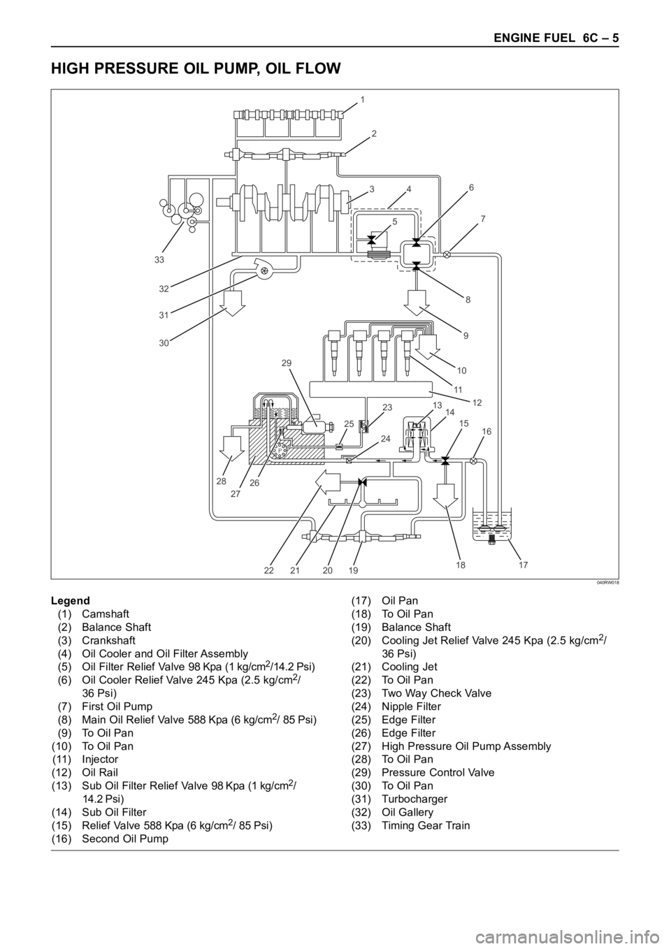
HIGH PRESSURE OIL PUMP, OIL FLOW
P
33
32
31
30
1
2
3
4
56
8
97
10
11
12
13
14 23 29
25
28
27262415
16
17 18
19 20 21 22
Legend
(1) Camshaft
(2) Balance Shaft
(3) Crankshaft
(4) Oil Cooler and Oil Filter Assembly
(5) Oil Filter Relief Valve 98 Kpa (1 kg/cm
2/14.2 Psi)
(6) Oil Cooler Relief Valve 245 Kpa (2.5 kg/cm2/
36 Psi)
(7) First Oil Pump
(8) Main Oil Relief Valve 588 Kpa (6 kg/cm
2/ 85 Psi)
(9) To Oil Pan
(10) To Oil Pan
(11) Injector
(12) Oil Rail
(13) Sub Oil Filter Relief Valve 98 Kpa (1 kg/cm
2/
14.2 Psi)
(14) Sub Oil Filter
(15) Relief Valve 588 Kpa (6 kg/cm
2/ 85 Psi)
(16) Second Oil Pump(17) Oil Pan
(18) To Oil Pan
(19) Balance Shaft
(20) Cooling Jet Relief Valve 245 Kpa (2.5 kg/cm
2/
36 Psi)
(21) Cooling Jet
(22) To Oil Pan
(23) Two Way Check Valve
(24) Nipple Filter
(25) Edge Filter
(26) Edge Filter
(27) High Pressure Oil Pump Assembly
(28) To Oil Pan
(29) Pressure Control Valve
(30) To Oil Pan
(31) Turbocharger
(32) Oil Gallery
(33) Timing Gear Train
040RW018
Page 5392 of 6000

ENGINE FUEL 6C – 11
REMOVAL
Prior to removal, be sure to confirm and record the
group code of the injector installed using Tech2.
1. Disconnect battery ground cable.
2. Remove air cleaner cover and air duct.
3. Remove intercooler.
Refer to “Intercooler” in this manual.
4. Remove PCV hose and pipe.
5. Remove cylinder head noise insulator cover.
6. Remove high pressure oil pipe.
CAUTION:
1) Sleeve nut should be loosened with cloth tied
around to prevent oil from spurting due to the
remaining pressure.
2) High oil pressure pipe should be disconnected
with cloth tied around the intake manifold glow
plug to prevent oil from flowing out of the oil
rail.
7. Loosen eye bolt of fuel pipe at fuel pump side.
NOTE: Cloth should be put around the loosened eye
bolt to prevent fuel from flowing out.
8. Remove fuel return hose at chassis side.
9. Remove PCV hose to cylinder head cover.
10. Remove cylinder head cover.
11. Drain the oil from oil rail assembly.
NOTE: Do not drop O-ring
12. Record the grade code of injector for each cylinder
that is indicated on the upper portion of injector.
There are nine kinds of grade code available, one
alphabet letter and one numeral letter.
Grade codeLegend
(1) Part Number
(2) Category Number (Grade code)
(3) Serial Number
(4) Bar Code
13. Remove harness connector from each injector.
14. Loosen nuts and bolts for oil rail.
15. Remove injector fixing bolts.
16. Remove injector clamp.
17. Remove injector assembly.
INSTALLATION
1. Install oil rail, tighten temporarily
2. Install injector assembly.
NOTE:
1) Do not forget to install O-ring between injector and
oil rail.
2) Use new O-ring
3) Clean O-ring groove and fitting surface of parts.
4) Apply engine oil to O-ring.
3. Install injector fixing bolts, tighten temporarily.
4. Install injector clamp, tighten nut temporarily.
5. Tighten injector fixing bolts to the specified torque.
Torque: 6.5 Nꞏm (0.7 kgꞏm / 5.1 lb ft)
6. Tighten injector clamp nut to the specified torque
with special method.
Torque: 30 Nꞏm (3.1 kgꞏm / 22.4 lb ft) then loosen a
time again tighten as following torque.
Torque: 25 Nꞏm (2.4 kgꞏm / 17.4 lb ft)
7. Tighten oil rail to the specified torque.
Torque: 20 Nꞏm (2.0 kgꞏm / 14.5 lb ft)
1
4
32
055RW00001
Category number
A– 1
A– 2
A– 3
B – 1
B – 2
B – 3
C – 1
C – 2
C – 3