low oil pressure OPEL FRONTERA 1998 Workshop Manual
[x] Cancel search | Manufacturer: OPEL, Model Year: 1998, Model line: FRONTERA, Model: OPEL FRONTERA 1998Pages: 6000, PDF Size: 97 MB
Page 4925 of 6000

6E–268
ENGINE DRIVEABILITY AND EMISSIONS
Lack of Power, Sluggish or Spongy Symptom
StepActionVa l u e ( s )Ye sNo
1DEFINITION:
Engine delivers less than expected power. Little or no
increase in speed when accelerator pedal is pushed
down part-way.
Was the “On-Board Diagnostic (OBD) System Check”
performed?
—Go to Step 2
Go to OBD
System
Check
21. Perform a bulletin search.
2. If a bulletin that addresses the symptom is found,
correct the condition as instructed in the bulletin.
Was a bulletin found that addresses the symptom?
—Verify repairGo to Step 3
3Was a visual/physical check performed?
—Go to Step 4
Go to
Visual/Physic
al Check
41. Remove and check the air filter element for dirt or
restrictions. Refer to
Air Intake System in
ON-Vehicle Service.
2. Replace the air filter element if necessary.
Was a repair required?
—Verify repairGo to Step 5
51. Check for low fuel pressure. Refer to Fuel System
Pressure Test
.
2. If a problem is found, repair as necessary.
Was a problem found?
—Verify repairGo to Step 6
61. Check for water- or alcohol-contaminated fuel.
2. If a problem is found, repair as necessary.
Was a problem found?
—Verify repairGo to Step 7
71. Using Tech 2, monitor the knock sensor (KS)
system for excessive spark retard activity. Refer to
Knock Sensor (KS) System.
2. If a problem is found, repair as necessary.
Was a problem found?
—Verify repairGo to Step 8
81. Check for proper ignition voltage output with spark
tester J 26792 (ST-125). Refer to
Electronic Ignition
System
for procedure.
2. If a problem is found, repair as necessary.
Was a problem found?
—Verify repairGo to Step 9
91. Remove the spark plugs and check for wet plugs,
cracks, wear, improper gap, burned electrodes, or
heavy deposits. Refer to
Electronic Ignition
System
.
NOTE: If spark plugs are gas or oil fouled, the cause of
the fouling must be determined before replacing the
spark plugs.
2. If a problem is found, repair as necessary.
Was a problem found?
—Verify repairGo to Step 10
101. Check the ignition coils for cracks or carbon
tracking.
2. If a problem is found, repair as necessary.
Was a problem found?
—Verify repairGo to Step 11
Page 4930 of 6000

6E–273 ENGINE DRIVEABILITY AND EMISSIONS
Rough, Unstable, or Incorrect Idle, Stalling Symptom
StepNo Ye s Va l u e ( s ) Action
101. Visually/physically inspect for the following
conditions:
Restricted air intake system. Check for a
possible collapsed air intake duct, restricted
air filter element, or foreign objects blocking
the air intake system.
Throttle body. Check for objects blocking the
IAC passage or throttle bore, excessive
deposits in the IAC passage and on the IAC
pintle, and excessive deposits in the throttle
bore and on the throttle plate.
Large vacuum leak. Check for a condition that
causes a large vacuum leak, such as an
incorrectly installed or faulty crankcase
ventilation valve or a disconnected brake
booster hose.
2. If a problem is found, repair as necessary.
Was a problem found?
—Verify repairGo to Step 8
11Check the injector connections. If any of the injectors
are connected to an incorrect cylinder, correct as
necessary.
Was a problem found?
—Verify repairGo to Step 12
121. Perform the “Injector Coil/Balance Test” in Fuel
Metering System
.
2. If a problem is found, repair as necessary.
Was a problem found?
—Verify repairGo to Step 13
131. Check for fuel in the pressure regulator vacuum
hose.
2. If fuel is present, replace the fuel pressure regulator
assembly. Refer to
Fuel Metering System.
3. If a problem is found, repair as necessary.
Was a problem found?
—Verify repairGo to Step 14
141. Check for proper ignition voltage output with spark
tester J 26792 (ST-125). Refer to
Electronic Ignition
System
for the procedure.
2. If a problem is found, repair as necessary.
Was a problem found?
—Verify repairGo to Step 15
151. Remove spark plugs. Check for wet plugs, cracks,
wear, improper gap, burned electrodes, or heavy
deposits. Refer to
Electronic Ignition System.
NOTE: If spark plugs are gas or oil fouled, the cause of
the fouling must be determined before replacing the
spark plugs.
2. If a problem is found, repair as necessary.
Was a problem found?
—Verify repairGo to Step 16
161. Check for a loose ignition coil ground.
Refer to
Electrical Ignition System.
2. If a problem is found, repair as necessary.
Was a problem found?
—Verify repairGo to Step 17
Page 4932 of 6000
6E–275 ENGINE DRIVEABILITY AND EMISSIONS
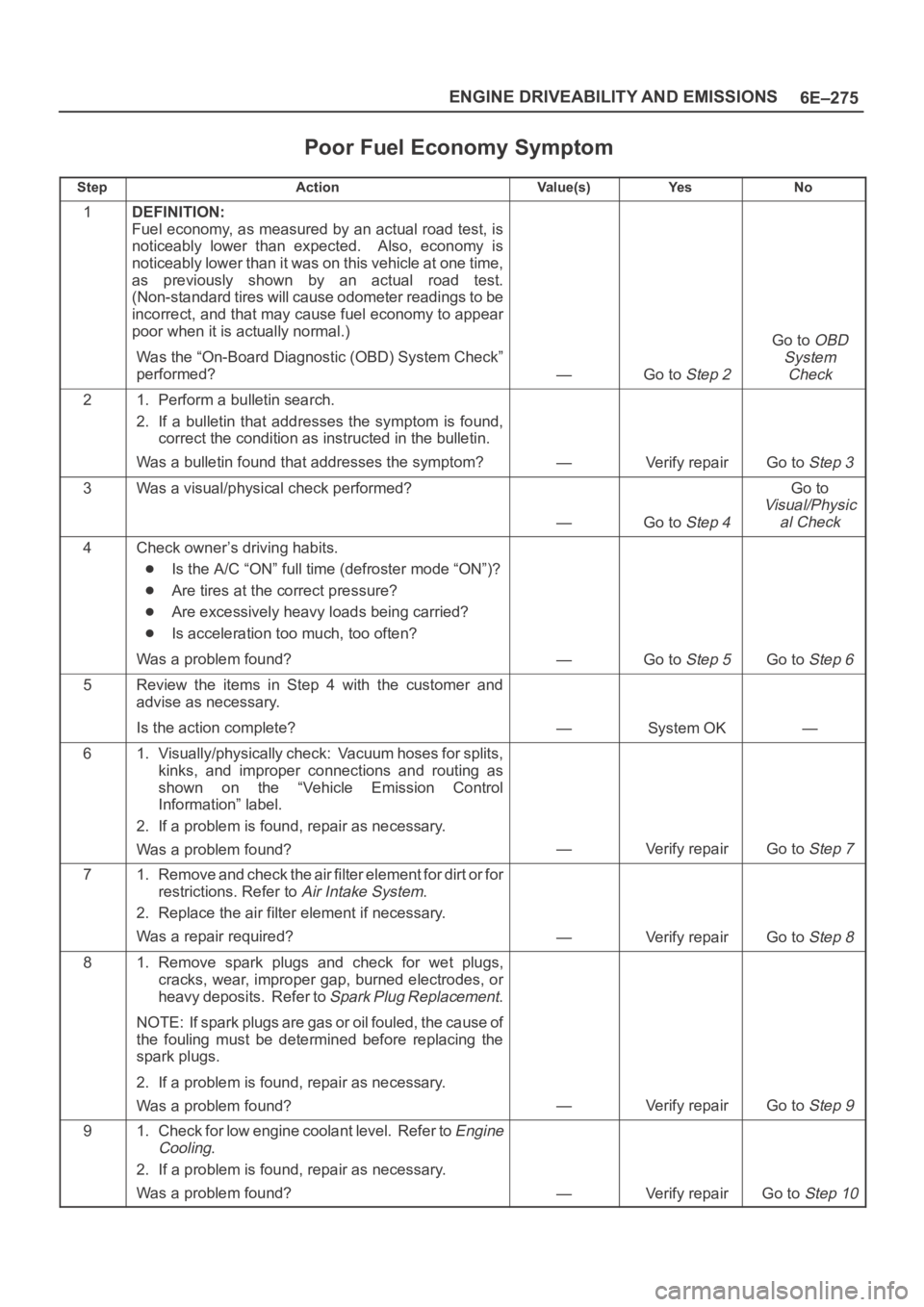
Poor Fuel Economy Symptom
StepActionVa l u e ( s )Ye sNo
1DEFINITION:
Fuel economy, as measured by an actual road test, is
noticeably lower than expected. Also, economy is
noticeably lower than it was on this vehicle at one time,
as previously shown by an actual road test.
(Non-standard tires will cause odometer readings to be
incorrect, and that may cause fuel economy to appear
poor when it is actually normal.)
Was the “On-Board Diagnostic (OBD) System Check”
performed?
—Go to Step 2
Go to OBD
System
Check
21. Perform a bulletin search.
2. If a bulletin that addresses the symptom is found,
correct the condition as instructed in the bulletin.
Was a bulletin found that addresses the symptom?
—Verify repairGo to Step 3
3Was a visual/physical check performed?
—Go to Step 4
Go to
Visual/Physic
al Check
4Check owner’s driving habits.
Is the A/C “ON” full time (defroster mode “ON”)?
Are tires at the correct pressure?
Are excessively heavy loads being carried?
Is acceleration too much, too often?
Was a problem found?
—Go to Step 5Go to Step 6
5Review the items in Step 4 with the customer and
advise as necessary.
Is the action complete?
—System OK—
61. Visually/physically check: Vacuum hoses for splits,
kinks, and improper connections and routing as
shown on the “Vehicle Emission Control
Information” label.
2. If a problem is found, repair as necessary.
Was a problem found?
—Verify repairGo to Step 7
71. Remove and check the air filter element for dirt or for
restrictions. Refer to
Air Intake System.
2. Replace the air filter element if necessary.
Was a repair required?
—Verify repairGo to Step 8
81. Remove spark plugs and check for wet plugs,
cracks, wear, improper gap, burned electrodes, or
heavy deposits. Refer to
Spark Plug Replacement.
NOTE: If spark plugs are gas or oil fouled, the cause of
the fouling must be determined before replacing the
spark plugs.
2. If a problem is found, repair as necessary.
Was a problem found?
—Verify repairGo to Step 9
91. Check for low engine coolant level. Refer to Engine
Cooling
.
2. If a problem is found, repair as necessary.
Was a problem found?
—Verify repairGo to Step 10
Page 4940 of 6000

6E–283 ENGINE DRIVEABILITY AND EMISSIONS
Cuts Out, Misses Symptom
StepNo Ye s Va l u e ( s ) Action
101. Visually/physically inspect for the following
conditions:
Restricted air intake system. Check for a
possible collapsed air intake duct, restricted
air filter element, or foreign objects blocking
the air intake system.
Throttle body. Check for objects blocking the
IAC passage or throttle bore, excessive
deposits in the IAC passage and on the IAC
pintle, and excessive deposits in the throttle
bore and on the throttle plate.
Large vacuum leak. Check for a condition that
causes a large vacuum leak, such as an
incorrectly installed or faulty PCV valve or
brake booster hose disconnected .
2. If a problem is found, repair as necessary.
Was a problem found?
—Verify repairGo to Step 8
11Check the injector connections. If any of the injectors
are connected to an incorrect cylinder, correct as
necessary.
Was a problem found?
—Verify repairGo to Step 12
121. Perform the “Injector Coil/Balance Test” in Fuel
Metering System
.
2. If a problem is found, repair as necessary.
Was a problem found?
—Verify repairGo to Step 13
131. Check for fuel in the pressure regulator vacuum
hose.
2. If fuel is present, replace the fuel pressure regulator
assembly. Refer to
Fuel Metering System.
3. If a problem is found, repair as necessary.
Was a problem found?
—Verify repairGo to Step 14
141. Check for proper ignition voltage output with spark
tester J 26792 (ST-125). Refer to
Electronic Ignition
System
for the procedure.
2. If a problem is found, repair as necessary.
Was a problem found?
—Verify repairGo to Step 15
151. Remove spark plugs. Check for wet plugs, cracks,
wear, improper gap, burned electrodes, or heavy
deposits. Refer to
Electronic Ignition System.
NOTE: If spark plugs are gas or oil fouled, the cause of
the fouling must be determined before replacing the
spark plugs.
2. If a problem is found, repair as necessary.
Was a problem found?
—Verify repairGo to Step 16
161. Check for a loose ignition coil ground.
Refer to
Electronic Ignition System.
2. If a problem is found, repair as necessary.
Was a problem found?
—Verify repairGo to Step 17
Page 5006 of 6000
6E–349 ENGINE DRIVEABILITY AND EMISSIONS
Damage during re-gapping can happen if the gapping
tool is pushed against the center electrode or the
insulator around it, causing the insulator to crack.
When re-gapping a spark plug, make the adjustment
by bending only the ground side terminal, keeping the
tool clear of other parts.
”Heat shock” breakage in the lower insulator tip
generally occurs during several engine operating
conditions (high speeds or heavy loading) and may be
caused by over-advanced timing or low grade fuels.
Heat shock refers to a rapid increase in the tip
temperature that causes the insulator material to
crack.
Spark plugs with less than the recommended amount of
service can sometimes be cleaned and re-gapped , then
returned to service. However, if there is any doubt about
the serviceability of a spark plug, replace it. Spark plugs
with cracked or broken insulators should always be
replaced.
A/C Clutch Diagnosis
A/C Clutch Circuit Operation
A 12-volt signal is supplied to the A/C request input of the
PCM when the A/C is selected through the A/C control
switch.
The A/C compressor clutch relay is controlled through the
PCM. This allows the PCM to modify the idle air control
position prior to the A/C clutch engagement for better idle
quality. If the engine operating conditions are within their
specified calibrated acceptable ranges, the PCM will
enable the A/C compressor relay. This is done by
providing a ground path for the A/C relay coil within the
PCM. When the A/C compressor relay is enabled,
battery voltage is supplied to the compressor clutch coil.
The PCM will enable the A/C compressor clutch
whenever the engine is running and the A/C has been
requested. The PCM will not enable the A/C compressor
clutch if any of the following conditions are met:
The throttle is greater than 90%.
The engine speed is greater than 6315 RPM.
The ECT is greater than 119C (246F).
The IAT is less than 5C (41F).
The throttle is more than 80% open.
A/C Clutch Circuit Purpose
The A/C compressor operation is controlled by the
powertrain control module (PCM) for the following
reasons:
It improvises idle quality during compressor clutch
engagement.
It improvises wide open throttle (WOT) performance.
It provides A/C compressor protection from operation
with incorrect refrigerant pressures.
The A/C electrical system consists of the following
components:
The A/C control head.
The A/C refrigerant pressure switches.
The A/C compressor clutch.
The A/C compressor clutch relay.
The PCM.
A/C Request Signal
This signal tells the PCM when the A/C mode is selected
at the A/C control head. The PCM uses this to adjust the
idle speed before turning on the A/C clutch. The A/C
compressor will be inoperative if this signal is not
available to the PCM.
Refer to
A/C Clutch Circuit Diagnosis for A/C wiring
diagrams and diagnosis for A/C electrical system.
General Description (Exhaust Gas
Recirculation (EGR) System)
EGR Purpose
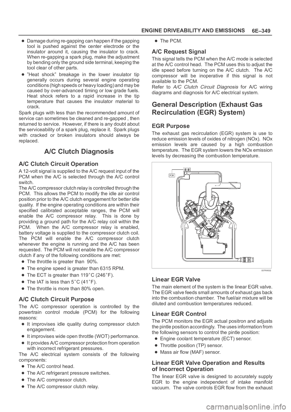
The exhaust gas recirculation (EGR) system is use to
reduce emission levels of oxides of nitrogen (NOx). NOx
emission levels are caused by a high combustion
temperature. The EGR system lowers the NOx emission
levels by decreasing the combustion temperature.
057RW002
Linear EGR Valve
The main element of the system is the linear EGR valve.
The EGR valve feeds small amounts of exhaust gas back
into the combustion chamber. The fuel/air mixture will be
diluted and combustion temperatures reduced.
Linear EGR Control
The PCM monitors the EGR actual positron and adjusts
the pintle position accordingly. The uses information from
the following sensors to control the pintle position:
Engine coolant temperature (ECT) sensor.
Throttle position (TP) sensor.
Mass air flow (MAF) sensor.
Linear EGR Valve Operation and Results
of Incorrect Operation
The linear EGR valve is designed to accurately supply
EGR to the engine independent of intake manifold
vacuum. The valve controls EGR flow from the exhaust
Page 5276 of 6000

ENGINE MECHANICAL 6A – 3
SERVICE INFORMATION
MAIN DATA AND SPECIFICATION
Engine type Diesel, four cycle water cooled inline
Camshaft type DOHC
Number of cylinders 4
Bore x stroke (mm) 95.4 x 104.9
Total piston displacement (cc) 2999
Compression ratio (to 1) 19.0
Engine weight (dry) N (kg/lb) 2492 (254/560) (A/T)
2649 (270/593) (M/T)
Engine idling speed (Reference) RPM 720
Compression pressure kpa (kg/cm
2/psi)-rpm 3000 (31/440)-200
Firing order 1–3–4–2
VALVE SYSTEM
Intake valves open at: B.T.D.C. 3°
close at: A.B.D.C. 57.6°
Exhaust valves open at: B.B.D.C. 56.5°
close at: A.T.D.C. 5°
Valve clearance at cold mm (in)
intake: 0.15 (0.006)
exhaust: 0.25 (0.01)
Oil filter Full flow and bypass combined type
Oil capacity (Original factory fill or rebuilt engine) 9.0 liters (7.9 US quarts)
Oil capacity (Service change)
with filter change 6.0 liters (6.3 US quarts)
without filter change 5.0 liters (5.3 US quarts)
Oil cooler Water cooled type
Inter cooler Air cooled type
Turbocharger method
Control method Wastegate control
Lubrication Pressurized control
Cooling method Coolant cooled
Page 5313 of 6000
6A – 40 ENGINE MECHANICAL
REMOVAL
1. Disconnect battery ground cable.
2. Drain engine coolant.
3. Remove air cleaner and air duct.
4. Remove intercooler assembly.
Refer to “Intercooler” in this manual.
5. Remove oil level gauge guide assembly.
6. Remove PCV hose.
7. Remove EGR vacuum hose.
8. Disconnect harness connector around the cylinder
head.
9. Remove A/C compressor assembly.
10. Remove A/C compressor bracket.
11. Remove generator assembly and take out fan belt.
12. Remove heat protector and remove valve
assembly.
13. Remove water hose and oil pipe from turbocharger.
14. Remove turbocharger assembly.
15. Remove water hose between thermostat and
radiator.
16. Remove cylinder head noise insulator cover.
NOTE: Do not make damage to the harness.
17. Remove high pressure pipe.
18. Remove timing belt cover.
19. Remove CMP sensor bracket.
20. Remove timing belt tensioner and remove timing
belt.
21. Remove camshaft pulley.
22. Remove front plate.
23. Remove water pipe between cylinder head and
water pump.
24. Remove fuel pipe between fuel pump and intake
manifold.
25. Remove fuel return pipe.
26. Remove intake manifold assembly.
27. Disconnect glow plug wiring and remove glow plug.
28. Remove cylinder head cover.
29. Drain oil from oil rail.
30. Disconnect injector harness connector.
31. Disconnect harness connector from oil pressure
sensor and oil temperature sensor on the oil rail.
32. Disconnect injector harness assembly.
33. Remove injector clamp.
34. Remove injector spacer.
35. Remove injector assembly.
36. Remove oil rail assembly.
37. Remove camshaft carrier.
38. Remove cylinder head assembly.
39. Remove cylinder gasket.
INSTALLATION
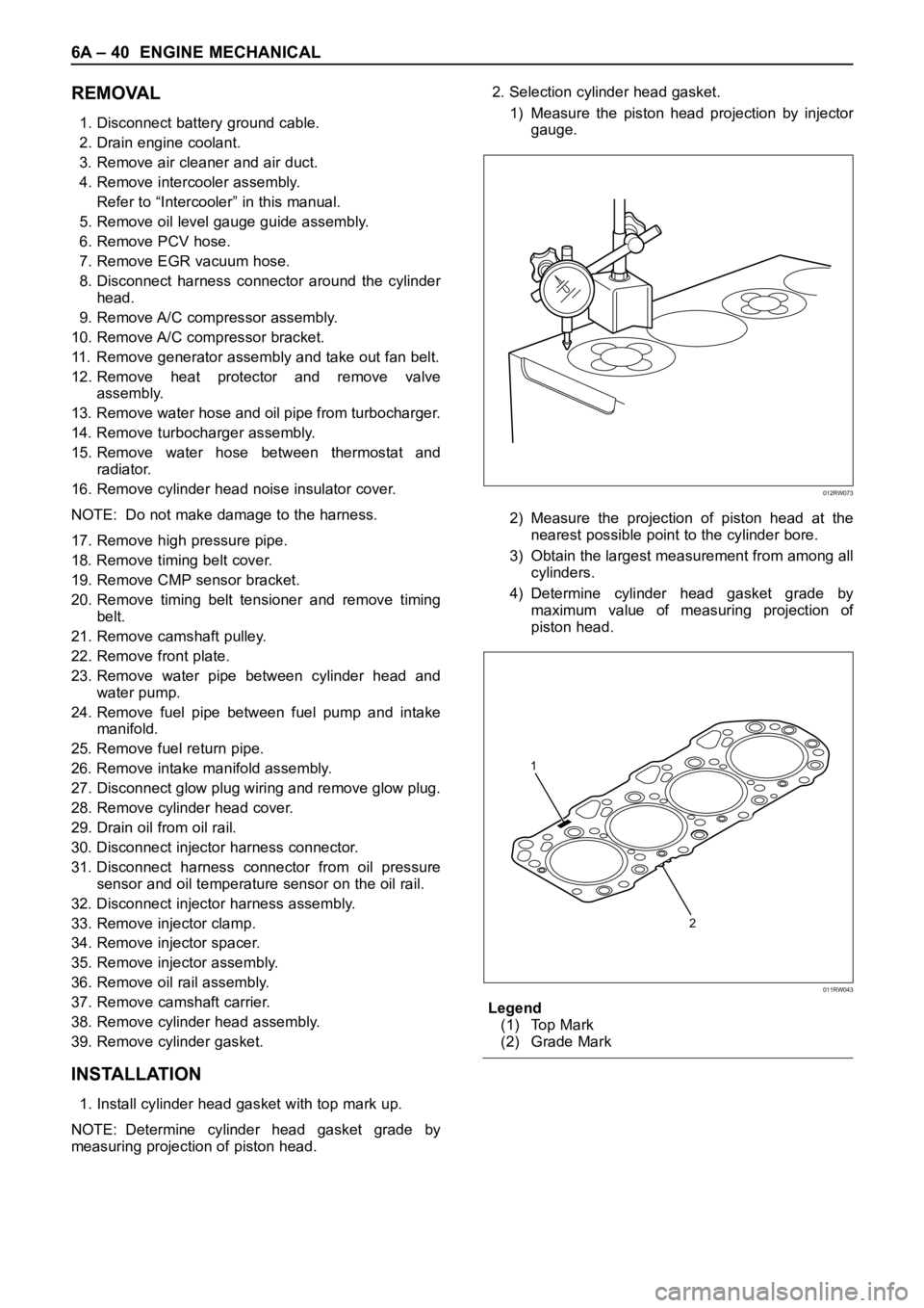
1. Install cylinder head gasket with top mark up.
NOTE: Determine cylinder head gasket grade by
measuring projection of piston head.2. Selection cylinder head gasket.
1) Measure the piston head projection by injector
gauge.
2) Measure the projection of piston head at the
nearest possible point to the cylinder bore.
3) Obtain the largest measurement from among all
cylinders.
4) Determine cylinder head gasket grade by
maximum value of measuring projection of
piston head.
Legend
(1) Top Mark
(2) Grade Mark
012RW073
2 1
011RW043
Page 5314 of 6000

ENGINE MECHANICAL 6A – 41
Cylinder head gasket and piston projection mm
CAUTION:
The projection of each piston should be 0.333
mm or more and less than 0.483 mm.
Maximum difference in projection between
pistons should be less than 0.1 mm.
If the piston projection is without standard,
reassemble the engine all over again.
3. Install cylinder head assembly, tighten bolts by
angular tightening method.
To r q u e :
1st step; 49 Nꞏm (4.9 kgꞏm/35.4 lb ft)
2nd step; 60°
3rd step; 60°
4. Install camshaft carrier assembly.
Refer to “Camshaft” in this manual.
5. Install oil rail and injector assembly.
Refer to “Oil rail and injector” in this manual.
6. Install injector harness to connect harness
connector.
Note: Apply liquid gasket (TB 1207B or equivalent) to
the rubber seal of the camshaft end, injector harness
gasket area and No. 1 camshaft bracket. Refer to the
Cylinder head cover.
7. Install cylinder head cover.
Torque: 9 Nꞏm (0.9 kgꞏm/6.5 lb ft)
8. Install glow plug to tighten specified torque.
Torque: 15 Nꞏm (1.5 kgꞏm/11 lb ft) and connect
glow plug harness.
9. Install intake manifold.Torque: 20 Nꞏm (2.0 kgꞏm/14.5 lb ft)
10. Install fuel return pipe.
11. Install fuel pipe in between fuel pump and intake
manifold.
12. Install water pipe in between cylinder head and
water pump.
Tighten flange bolt to the specified torque.
Torque: 20 Nꞏm (2.0 kgꞏm/14.5 lb ft)
13. Install front plate.
Torque: 20 Nꞏm (2.0 kgꞏm/14.5 lb ft)
14. Install camshaft pulley, tighten with angular
tightening method.
1st step 40 Nꞏm (4.0 kgꞏm/29 lb ft)
2nd step 60°
NOTE: Apply engine oil to camshaft pulley bolt.
15. Align timing mark oil pump pulley and camshaft
pulley to front plate then put the timing belt and
tighten tensioner bolt.
Torque: 20 Nꞏm (2.0 kgꞏm/14.5 lb ft) for M8
50 Nꞏm (5.1 kgꞏm/37 lb ft)
16. Install CMP sensor bracket.
17. Install timing belt cover.
Torque: 9 Nꞏm (0.9 kgꞏm/6.5 lb ft)
18. Fill with about 300 cc of engine oil from the high
pressure oil pipe installing port of oil rail using an oil
filler.
If assembled without filling the oil rail with oil, the
time for engine start will be longer.
19. Immediately install high pressure oil pipe to tighten
with specified torque.
Torque: 80 Nꞏm (8 kgꞏm/57.9 lb ft)
20. Install cylinder head noise insulator cover.
Torque: 9 Nꞏm (0.9 kgꞏm/6.5 lb ft)
Grade A Grade B Grade C
011RW042
Grade Piston projectionGasket
thickness
A more 0.333 to less 0.383 1.35
B more 0.383 to less 0.433 1.40
C more 0.433 to less 0.483 1.45
Page 5329 of 6000

6A – 56 ENGINE MECHANICAL
VALVE STEM SEAL, VALVE SPRING AND ADJUSTER
REMOVAL
1. Disconnect battery ground cable.
2. Drain engine coolant.
3. Remove the air duct from between air cleaner and
turbocharger.
4. Remove intercooler assembly.
Refer to “Intercooler” in this manual.
5. Remove oil level gauge guide assembly.
6. Disconnect PCV hose.
7. Disconnect EGR vacuum hose.
8. Disconnect harness connectors around the cylinder
head such as the injector, CMP sensor, MAP
sensor, EGR sensor, EVRV, IAT sensor, A/C
compressor, TP stepping motor, TP sensor and fuel
temperature sensor etc.
9. Remove A/C compressor assembly.
10. Remove A/C compressor bracket.
11. Remove generator assembly and take out drivebelt.
12. Remove heat protector, remove exhaust valve
assembly.
13. Remove water cooling hose and lubrication pipe for
turbocharger.
14. Remove turbocharger assembly.
15. Remove hose between thermostat and radiator.
16. Remove noise insulator cover of cylinder head.
NOTE: Do not damage injector harness.
17. Remove high pressure oil pipe.
18. Remove timing belt cover.
19. Remove CMP sensor bracket.
20. Remove timing belt tensioner then remove timing
belt.
21. Remove camshaft pulley.
22. Remove front plate.
23. Remove engine coolant pipe between cylinder
head and water pump.
1
2
3
4
5
6
9
10
7
8
011RW031
Legend
(1) Adjuster
(2) Tappet
(3) Split Collar
(4) Spring Seat Upper
(5) Valve Spring(6) Spring Seat Lower
(7) Valve Stem Seal
(8) Valve Guide
(9) Valve Seat
(10) Valve
Page 5330 of 6000
ENGINE MECHANICAL 6A – 57
24. Remove fuel pipe between fuel pump and intake
manifold.
25. Remove fuel return pipe from rear of cylinder head.
26. Remove intake manifold assembly.
27. Disconnect glow plug harness and remove glow
plug.
28. Remove cylinder head cover.
29. Remove injector harness connector.
30. Disconnect harness connector from oil pressure
sensor and oil temperature sensor on the oil rail.
31. Remove injector harness assembly.
32. Remove injector clamp.
33. Remove injector is fixed bolts.
34. Remove injector assembly.
35. Remove oil rail.
36. Remove camshaft carrier assembly with camshaft.
37. Remove cylinder head assembly.
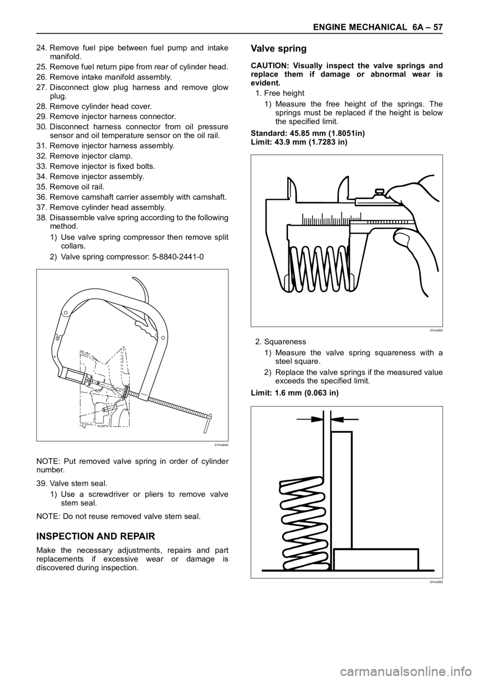
38. Disassemble valve spring according to the following
method.
1) Use valve spring compressor then remove split
collars.
2) Valve spring compressor: 5-8840-2441-0
NOTE: Put removed valve spring in order of cylinder
number.
39. Valve stem seal.
1) Use a screwdriver or pliers to remove valve
stem seal.
NOTE: Do not reuse removed valve stem seal.
INSPECTION AND REPAIR
Make the necessary adjustments, repairs and part
replacements if excessive wear or damage is
discovered during inspection.
Va l v e s p r i n g
CAUTION: Visually inspect the valve springs and
replace them if damage or abnormal wear is
evident.
1. Free height
1) Measure the free height of the springs. The
springs must be replaced if the height is below
the specified limit.
Standard: 45.85 mm (1.8051in)
Limit: 43.9 mm (1.7283 in)
2. Squareness
1) Measure the valve spring squareness with a
steel square.
2) Replace the valve springs if the measured value
exceeds the specified limit.
Limit: 1.6 mm (0.063 in)
014rw042
014rs004
014rs005