brake fluid OPEL FRONTERA 1998 User Guide
[x] Cancel search | Manufacturer: OPEL, Model Year: 1998, Model line: FRONTERA, Model: OPEL FRONTERA 1998Pages: 6000, PDF Size: 97 MB
Page 1144 of 6000
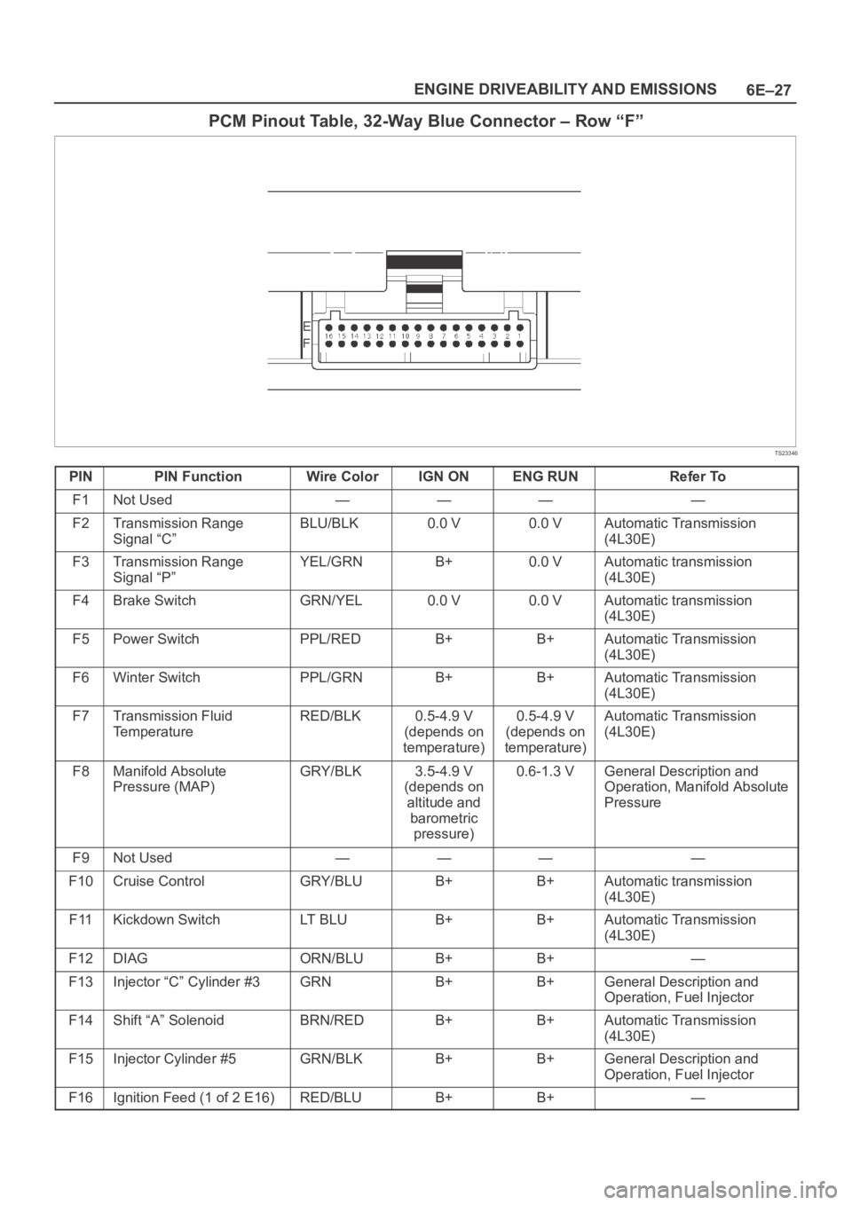
6E–27 ENGINE DRIVEABILITY AND EMISSIONS
PCM Pinout Table, 32-Way Blue Connector – Row “F”
TS23346
PINPIN FunctionWire ColorIGN ONENG RUNRefer To
F1Not Used————
F2Transmission Range
Signal “C”BLU/BLK0.0 V0.0 VAutomatic Transmission
(4L30E)
F3Transmission Range
Signal “P”YEL/GRNB+0.0 VAutomatic transmission
(4L30E)
F4Brake SwitchGRN/YEL0.0 V0.0 VAutomatic transmission
(4L30E)
F5Power SwitchPPL/REDB+B+Automatic Transmission
(4L30E)
F6Winter SwitchPPL/GRNB+B+Automatic Transmission
(4L30E)
F7Transmission Fluid
TemperatureRED/BLK0.5-4.9 V
(depends on
temperature)0.5-4.9 V
(depends on
temperature)Automatic Transmission
(4L30E)
F8Manifold Absolute
Pressure (MAP)GRY/BLK3.5-4.9 V
(depends on
altitude and
barometric
pressure)0.6-1.3 VGeneral Description and
Operation, Manifold Absolute
Pressure
F9Not Used————
F10Cruise ControlGRY/BLUB+B+Automatic transmission
(4L30E)
F11Kickdown SwitchLT B L UB+B+Automatic Transmission
(4L30E)
F12DIAGORN/BLUB+B+—
F13Injector “C” Cylinder #3GRNB+B+General Description and
Operation, Fuel Injector
F14Shift “A” SolenoidBRN/REDB+B+Automatic Transmission
(4L30E)
F15Injector Cylinder #5GRN/BLKB+B+General Description and
Operation, Fuel Injector
F16Ignition Feed (1 of 2 E16)RED/BLUB+B+—
Page 1870 of 6000

ENGINE ELECTRICAL 6D – 3
ON-VEHICLE SERVICE
BATTERY CHARGING
Observe the following safety precautions when
charging the battery:
1. Never attempt to charge the battery when the fluid
level is below the lower level line on the side of the
battery. In this case, the battery must be replaced.
2. Pay close attention to the battery during the
charging procedure.
Battery charging should be discontinued or the rate
of charge reduced if the battery feels hot to the
touch.
Battery charging should be discontinued or the rate
of charge reduced if the battery begins to gas or
spew electrolyte from the vent holes.
3. In order to more easily view the hydrometer blue
dot or ring, it may be necessary to jiggle or tilt the
battery.
4. Battery temperature can have a great effect on
battery charging capacity.
5. The sealed battery used on this vehicle may be
either quick-charged or slow-charged in the same
manner as other batteries.
Whichever method you decide to use, be sure that
you completely charge the battery. Never partially
charge the battery.
JUMP STARTING
JUMP STARTING WITH AN AUXILIARY
(BOOSTER) BATTERY
CAUTION: Never push or tow the vehicle in an
attempt to start it. Serious damage to the emission
system as well as other vehicle parts will result.
Treat both the discharged battery and the booster
battery with great care when using jumper cables.
Carefully follow the jump starting procedure, being
careful at all times to avoid sparking.
WARNING: Failure to carefully follow the jump
starting procedure could result in the following:
1. Serious personal injury, particularly to your
eyes.
2. Property damage from a battery explosion,
battery acid, or an electrical fire.
3. Damage to the electronic components of one or
both vehicles.
Never expose the battery to an open flame or electrical
spark. Gas generated by the battery may catch fire or
explode. Remove any rings, watches, or other jewelry
before working around the battery. Protect your eyes by
wearing an approved set of goggles.
Never allow battery fluid to come in contact with your
eyes or skin.
Never allow battery fluid to come in contact with fabrics
or painted surfaces.
Battery fluid is a highly corrosive acid.Should battery fluid come in contact with your eyes,
skin, fabric, or a painted surface, immediately and
thoroughly rinse the affected area with clean tap water.
Never allow metal tools or jumper cables to come in
contact with the positive battery terminal, or any other
metal surface of the vehicle. This will protect against a
short circuit.
Always keep batteries out of the reach of young
children.
JUMP STARTING PROCEDURE
1. Set the vehicle parking brake.
If the vehicle is equipped with an automatic
transmission, place the selector lever in the “PARK”
position.
If the vehicle is equipped with a manual
transmission place the shift lever in the “NEUTRAL”
position.
Turn “OFF” the ignition.
Turn “OFF” all lights and any other accessory
requiring electrical power.
2. Look at the built-in hydrometer.
If the indication area of the built-in hydrometer is
completely clear, do not try to jump start.
3. Attach the end of one jumper cable to the positive
terminal of the booster battery.
Attach the other end of the same cable to the
positive terminal of the discharged battery.
Do not allow the vehicles to touch each other.
This will cause a ground connection, effectively
neutralizing the charging procedure.
Be sure that the booster battery has a 12 volt rating.
4. Attach one end of the remaining cable to the
negative terminal of the booster battery.
Attach the other end of the same cable to a solid
engine ground (such as the A/C compressor
bracket or the generator mounting bracket) of the
vehicle with the discharged battery.
This ground connection must be at least 450 mm
(18 in) from the battery of the vehicle whose battery
is being charged.
WARNING: Never attach the end of the jumper
cable directly to the negative terminal of the dead
battery.
5. Start the engine of the vehicle with the good battery.
Make sure that all unnecessary electrical
accessories have been turned “OFF”.
6. Start the engine of the vehicle with the dead battery.
7. To remove the jumper cables, follow the above
directions in the reverse order.
Be sure to first disconnect the negative cable from
the vehicle with the discharged battery.
Page 2164 of 6000
7A–10
AUTOMATIC TRANSMISSION (4L30–E)
Checking Transmission Fluid Level
and Condition
Checking fluid level and condition (color and odor) at
regular intervals will provide early diagnosis information
about the transmission. This information may be used to
correct a condition that, if not detected early, could result
in major transmission repairs.
IMPORTANT:When new, automatic transmission fluid
is red in color. As the vehicle is driven, the transmission
fluid will begin to look darker in color. The color may
eventually appear light brown.
A dark brown color with burnt odor may indicate
excessive fluid deterioration and signal a need for fluid
change.
Fluid Level
When adding or changing fluid, use only DEXRON –III.
Refer to Maintenance and Lubrication in General
Information section for maintenance information and
servicing interval.
CAUTION: DO NOT OVERFILL.
Overfilling will cause foaming, loss of fluid, abnor-
mal shifting and possible damage to the transmis-
sion.
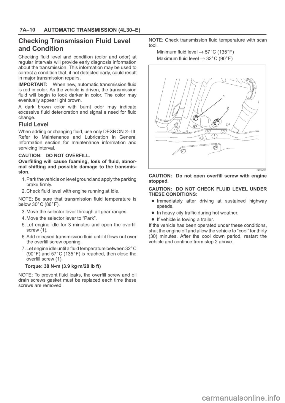
1. Park the vehicle on level ground and apply the parking
brake firmly.
2. Check fluid level with engine running at idle.
NOTE: Be sure that transmission fluid temperature is
below 30
C (86F).
3. Move the selector lever through all gear ranges.
4. Move the selector lever to “Park”.
5. Let engine idle for 3 minutes and open the overfill
screw (1).
6. Add released transmission fluid until it flows out over
the overfill screw opening.
7. Let engine idle until a fluid temperature between 32
C
(90
F) and 57C (135F) is reached, then close the
overfill screw (1).
Torque: 38 N
m (3.9 kgꞏm/28 lb ft)
NOTE: To prevent fluid leaks, the overfill screw and oil
drain screws gasket must be replaced each time these
screws are removed.NOTE: Check transmission fluid temperature with scan
tool.
Minimum fluid level
57C (135F)
Maximum fluid level
32C (90F)
242RW003
CAUTION: Do not open overfill screw with engine
stopped.
CAUTION: DO NOT CHECK FLUID LEVEL UNDER
THESE CONDITIONS:
Immediately after driving at sustained highway
speeds.
In heavy city traffic during hot weather.
If vehicle is towing a trailer.
If the vehicle has been operated under these conditions,
shut the engine off and allow the vehicle to “cool” for thirty
(30) minutes. After the cool down period, restart the
vehicle and continue from step 2 above.
Page 2167 of 6000
7A–13 AUTOMATIC TRANSMISSION (4L30–E)
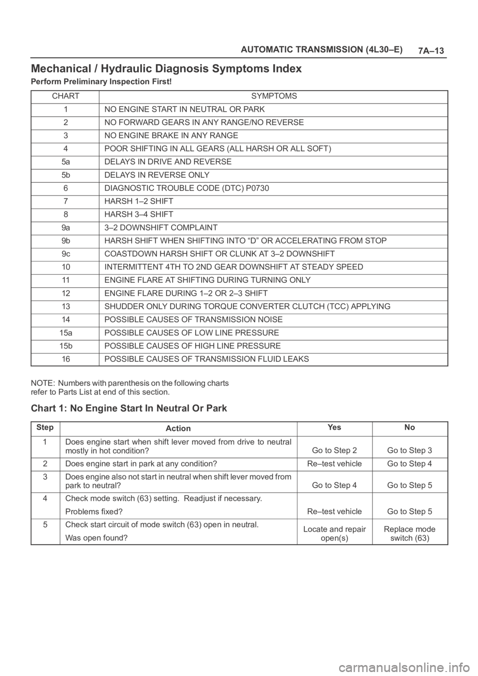
Mechanical / Hydraulic Diagnosis Symptoms Index
Perform Preliminary Inspection First!
CHART
SYMPTOMS
1NO ENGINE START IN NEUTRAL OR PARK
2NO FORWARD GEARS IN ANY RANGE/NO REVERSE
3NO ENGINE BRAKE IN ANY RANGE
4POOR SHIFTING IN ALL GEARS (ALL HARSH OR ALL SOFT)
5aDELAYS IN DRIVE AND REVERSE
5bDELAYS IN REVERSE ONLY
6DIAGNOSTIC TROUBLE CODE (DTC) P0730
7HARSH 1–2 SHIFT
8HARSH 3–4 SHIFT
9a3–2 DOWNSHIFT COMPLAINT
9bHARSH SHIFT WHEN SHIFTING INTO “D” OR ACCELERATING FROM STOP
9cCOASTDOWN HARSH SHIFT OR CLUNK AT 3–2 DOWNSHIFT
10INTERMITTENT 4TH TO 2ND GEAR DOWNSHIFT AT STEADY SPEED
11ENGINE FLARE AT SHIFTING DURING TURNING ONLY
12ENGINE FLARE DURING 1–2 OR 2–3 SHIFT
13SHUDDER ONLY DURING TORQUE CONVERTER CLUTCH (TCC) APPLYING
14POSSIBLE CAUSES OF TRANSMISSION NOISE
15aPOSSIBLE CAUSES OF LOW LINE PRESSURE
15bPOSSIBLE CAUSES OF HIGH LINE PRESSURE
16POSSIBLE CAUSES OF TRANSMISSION FLUID LEAKS
NOTE: Numbers with parenthesis on the following charts
refer to Parts List at end of this section.
Chart 1: No Engine Start In Neutral Or Park
StepActionYe sNo
1Does engine start when shift lever moved from drive to neutral
mostly in hot condition?
Go to Step 2Go to Step 3
2Does engine start in park at any condition?Re–test vehicleGo to Step 4
3Does engine also not start in neutral when shift lever moved from
park to neutral?
Go to Step 4Go to Step 5
4Check mode switch (63) setting. Readjust if necessary.
Problems fixed?
Re–test vehicleGo to Step 5
5Check start circuit of mode switch (63) open in neutral.
Was open found?Locate and repair
open(s)Replace mode
switch (63)
Page 2177 of 6000

7A–23 AUTOMATIC TRANSMISSION (4L30–E)
Stall Test
The stall test allows you to check the transmission for
internal abrasion and the one way clutch for slippage.
Torque converter performance can also be evaluated.
The stall test results together with the road test results will
identify transmission components requiring servicing or
adjustment.
Stall Test Procedure:
1. Check the level of the engine coolant, the engine oil,
and the automatic transmission fluid. Replenish if
necessary.
2. Block the wheels and set the parking brake.
3. Connect a tachometer to the engine.
4. Start the engine and allow it to idle until the engine
coolant temperature reaches 70 – 80
C (158 –
176
F).
5. Hold the brake pedal down as far as it will go.
6. Place the selector in the “D” range.
7. Gradually push the accelerator pedal to the floor.
The throttle valve will be fully open.
Note the engine speed at which the tachometer
needle stabilizes.
Stall Speed : 2,100
150 rpm
NOTE: Do not continuously run this test longer than 5
seconds.
8. Release the accelerator pedal.
9. Place the selector in the “N” range.
10. Run the engine at 1,200 rpm for one minute.
This will cool the transmission fluid.
11. Repeat Steps 7 – 10 for the “3”, “2”, “L” and “R”
ranges.
Line Pressure Test
The line pressure test checks oil pump and control valve
pressure regulator valve function. It will also detect oil
leakage.
Line Pressure Test Procedure:
1. Check the level of the engine coolant, the engine oil,
and the automatic transmission fluid.
Replenish if required.
2. Block the wheels and set the parking brake.
3. Remove the pressure detection plug at the left side of
the transmission case.
Set 5–8840–0004–0 pressure gauge and adapter to
the pressure detection plug hole.
241RS001
4. Start the engine and allow it to idle until the engine
coolant temperature reaches 70 – 80
C (158 –
176
F).
5. Hold the brake pedal down as far as it will go.
6. Place the selector in the “D” range.
7. Note the pressure gauge reading with the engine
idling.
8. Gradually push the accelerator pedal to the floor. The
throttle valve will be fully open.
Note the pressure gauge reading with the accelerator
pedal fully depressed.
NOTE: Do not continuously run this test longer than 5
seconds.
9. Release the accelerator pedal.
10. Place the selector in the “N” range.
11. Run the engine at 1,200 rpm for one minute.
This will cool the transmission fluid.
12. Repeat Steps 7 – 11 for the “3”, “2”, “L”, and “R”
ranges.
13. Install a pressure detection plug to the transmission
case, applying recommended thread locking agent
(LOCTITE 242) or its equivalent to thread of plug.
Make sure that thread is cleaned before applying
locking agents.
14. Tighten the pressure detection plug to the specified
torque.
Torque:9–14Nꞏm(0.9–1.4kgꞏm/7–10lbft)
Page 2197 of 6000

7A–43 AUTOMATIC TRANSMISSION (4L30–E)
Rear Oil Seal (Extension Housing)
Removal
1. Remove transfer case assembly from the vehicle.
Refer to Transfer Case in Drive Line/Axle section.
2. Remove rear oil seal from transmission extension
housing.
241RW005
Installation
1. Use 5–8840–2282–0 (J–36797) extension housing
oil seal installer, and install the rear oil seal to the
transmission extension housing.
2. Install the transfer case assembly to the vehicle.
Refer to Transfer Case in Drive Line/Axle section.
Transmission (4L30–E)
Disassembly
NOTE: During the disassembly and reassembly, perform
the following:
Wash each part thoroughly, and blow air through each
oil passage and groove to eliminate blockage.
Seal rings, roll pins, and gaskets should be replaced.
When assembling the components, apply
DEXRON
–III Automatic Transmission Fluid (ATF)
to each seal, rotating part, and sliding part.
Do not dip part facings, such as clutch or brake drive
plates, in cleaner when washing it.
Also, always coat parts with new ATF two or three
times after cleaning with solvent.
1. Remove torque converter (1).
Drain fluid from torque converter.
Attach 5–8840–2278–0 (J–8763–02) holding
fixture to the transmission and set it on
5–8840–0003–0 (J–3289–20) holding fixture base.
NOTE: Do not overtighten the tool, as case damage may
result.
420RW019
2. Remove O–ring (2) from turbine shaft.
3. Remove two 10mm mode switch screws, selector
lever nut, cover, and mode switch (3).
4. Remove twelve 10mm adapter case oil pan (4) fixing
screws, adapter oil pan, and gasket.
5. Disconnect electrical wiring connections (5) from
solenoids and 5 pin connector of adapter case. Pull
on connectors only, not on wiring harness.
Page 2246 of 6000
TRANSMISSION CONTROL SYSTEM (4L30–E)7A1–1
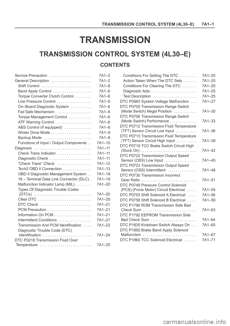
TRANSMISSION
TRANSMISSION CONTROL SYSTEM (4L30–E)
CONTENTS
Service Precaution 7A1–2. . . . . . . . . . . . . . . . . . . . . .
General Description 7A1–2. . . . . . . . . . . . . . . . . . . . .
Shift Control 7A1–6. . . . . . . . . . . . . . . . . . . . . . . . . .
Band Apply Control 7A1–6. . . . . . . . . . . . . . . . . . . .
Torque Converter Clutch Control 7A1–6. . . . . . . . .
Line Pressure Control 7A1–6. . . . . . . . . . . . . . . . . .
On–Board Diagnostic System 7A1–6. . . . . . . . . . .
Fail Safe Mechanism 7A1–6. . . . . . . . . . . . . . . . . . .
Torque Management Control 7A1–6. . . . . . . . . . . .
ATF Warning Control 7A1–6. . . . . . . . . . . . . . . . . . .
ABS Control (If equipped) 7A1–6. . . . . . . . . . . . . .
Winter Drive Mode 7A1–9. . . . . . . . . . . . . . . . . . . . .
Backup Mode 7A1–9. . . . . . . . . . . . . . . . . . . . . . . . .
Functions of Input / Output Components 7A1–10. .
Diagnosis 7A1–11. . . . . . . . . . . . . . . . . . . . . . . . . . . . . .
Check Trans Indicator 7A1–11. . . . . . . . . . . . . . . . . .
Diagnostic Check 7A1–11. . . . . . . . . . . . . . . . . . . . . .
“Check Trans” Check 7A1–12. . . . . . . . . . . . . . . . . .
Tech2 OBD II Connection 7A1–13. . . . . . . . . . . . . . .
OBD II Diagnostic Management System 7A1–18. .
16 – Terminal Data Link Connector (DLC) 7A1–19.
Malfunction Indicator Lamp (MIL) 7A1–20. . . . . . . .
Types Of Diagnostic Trouble Codes
(DTCs) 7A1–20. . . . . . . . . . . . . . . . . . . . . . . . . . . . . .
Clear DTC 7A1–20. . . . . . . . . . . . . . . . . . . . . . . . . . . .
DTC Check 7A1–21. . . . . . . . . . . . . . . . . . . . . . . . . . .
PCM Precaution 7A1–21. . . . . . . . . . . . . . . . . . . . . . .
Information On PCM 7A1–21. . . . . . . . . . . . . . . . . . .
Intermittent Conditions 7A1–21. . . . . . . . . . . . . . . . .
Transmission And PCM Identification 7A1–22. . . . .
Diagnostic Trouble Code (DTC)
Identification 7A1–24. . . . . . . . . . . . . . . . . . . . . . . . .
DTC P0218 Transmission Fluid Over
Temperature 7A1–25. . . . . . . . . . . . . . . . . . . . . . . . . . . Conditions For Setting The DTC 7A1–25. . . . . . . . .
Action Taken When The DTC Sets 7A1–25. . . . . . .
Conditions For Clearing The DTC 7A1–25. . . . . . . .
Diagnostic Aids 7A1–25. . . . . . . . . . . . . . . . . . . . . . . .
Test Description 7A1–25. . . . . . . . . . . . . . . . . . . . . . .
DTC P0560 System Voltage Malfunction 7A1–27. . .
DTC P0705 Transmission Range Switch
(Mode Switch) Illegal Position 7A1–30. . . . . . . . . . . .
DTC P0706 Transmission Range Switch
(Mode Switch) Performance 7A1–33. . . . . . . . . . . . . .
DTC P0712 Transmission Fluid Temperature
(TFT) Sensor Circuit Low Input 7A1–36. . . . . . . . . . .
DTC P0713 Transmission Fluid Temperature
(TFT) Sensor Circuit High Input 7A1–39. . . . . . . . . . .
DTC P0719 TCC Brake Switch Circuit High
(Stuck On) 7A1–42. . . . . . . . . . . . . . . . . . . . . . . . . . . . .
DTC P0722 Transmission Output Speed
Sensor (OSS) Low Input 7A1–45. . . . . . . . . . . . . . . . .
DTC P0723 Transmission Output Speed
Sensor (OSS) Intermittent 7A1–48. . . . . . . . . . . . . . .
DTC P0730 Transmission Incorrect
Gear Ratio 7A1–51. . . . . . . . . . . . . . . . . . . . . . . . . . . . .
DTC P0748 Pressure Control Solenoid
(PCS) (Force Motor) Circuit Electrical 7A1–54. . . . .
DTC P0753 Shift Solenoid A Electrical 7A1–56. . . . .
DTC P0758 Shift Solenoid B Electrical 7A1–59. . . . .
DTC P1790 ROM Transmission Side Bad
Check Sum 7A1–63. . . . . . . . . . . . . . . . . . . . . . . . . . . .
DTC P1792 EEPROM Transmission Side
Bad Check Sum 7A1–64. . . . . . . . . . . . . . . . . . . . . . . .
DTC P1835 Kickdown Switch Always On 7A1–65. . .
DTC P1850 Brake Band Apply Solenoid
Malfunction 7A1–67. . . . . . . . . . . . . . . . . . . . . . . . . . . .
DTC P1860 TCC Solenoid Electrical 7A1–71. . . . . . .
Page 2269 of 6000

7A1–24
TRANSMISSION CONTROL SYSTEM (4L30–E)
Diagnostic Trouble Code (DTC)
Identification
DTC NUM-
BERDTC NAMEDTC TYPE“CHECK
TRANS”
P0218Transmission Fluid Over TemperatureD
P0560System Voltage MalfunctionCFlash
P0705Transmission Range Switch (Mode Switch) Illegal PositionD
P0706Transmission Range Switch (Mode Switch) PerformanceD
P0712Transmission Fluid Temperature Sensor Circuit Low Input
(TFT)D
P0713Transmission Fluid Temperature (TFT) Sensor Circuit High
InputD
P0719TCC Brake Switch Circuit High (Stuck ON)D
P0722Transmission Output Speed Sensor (OSS) Low InputCFlash
P0723Transmission Output Speed Sensor (OSS) IntermittentCFlash
P0730Transmission Incorrect Gear Ratio FlashCFlash
P0748Pressure Control Solenoid (PCS) (FORCE MOTOR) Circuit
ElectricalCFlash
P0753Shift Solenoid A ElectricalCFlash
P0758Shift Solenoid B ElectricalCFlash
P1790ROM Transmission Side Bad Check SumCFlash
P1792EEPROM Transmission Side Bad Check SumCFlash
P1835Kickdown Switch Always OND
P1850Brake Band Apply Solenoid MalfunctionD
P1860TCC Solenoid ElectricalD
DTC TYPEDEFINITION
CFlashing Check Trans on 1st failure
DNo lamps
NOTE: On the following charts, refer to the Powertrain
Control Module (PCM) section for the Wiring System, and
the Body and Accessories section for circuit diagram
details, parts location, and connector configuration.
Page 2312 of 6000
TRANSMISSION CONTROL SYSTEM (4L30–E)7A1–67
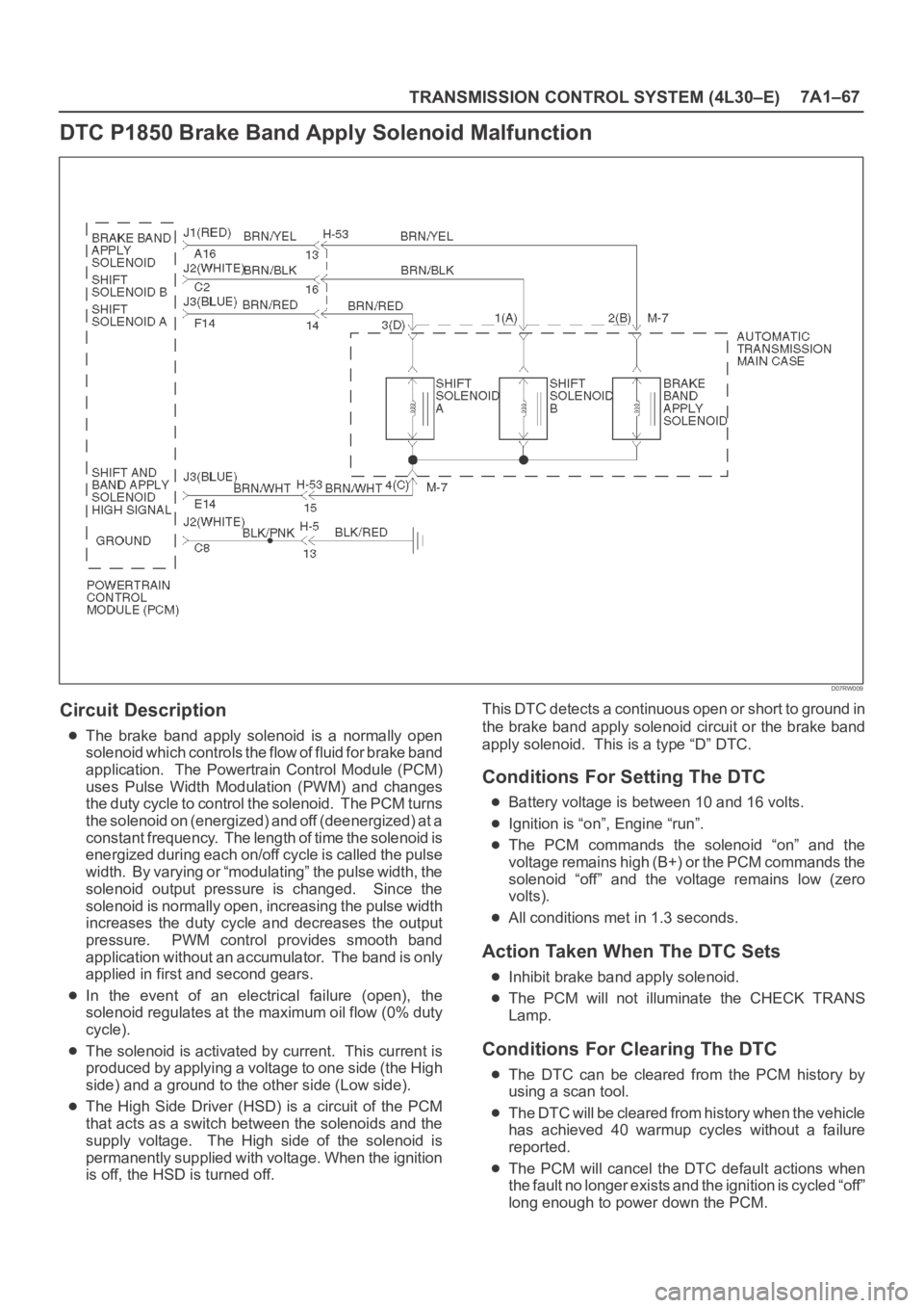
DTC P1850 Brake Band Apply Solenoid Malfunction
D07RW009
Circuit Description
The brake band apply solenoid is a normally open
solenoid which controls the flow of fluid for brake band
application. The Powertrain Control Module (PCM)
uses Pulse Width Modulation (PWM) and changes
the duty cycle to control the solenoid. The PCM turns
the solenoid on (energized) and off (deenergized) at a
constant frequency. The length of time the solenoid is
energized during each on/off cycle is called the pulse
width. By varying or “modulating” the pulse width, the
solenoid output pressure is changed. Since the
solenoid is normally open, increasing the pulse width
increases the duty cycle and decreases the output
pressure. PWM control provides smooth band
application without an accumulator. The band is only
applied in first and second gears.
In the event of an electrical failure (open), the
solenoid regulates at the maximum oil flow (0% duty
cycle).
The solenoid is activated by current. This current is
produced by applying a voltage to one side (the High
side) and a ground to the other side (Low side).
The High Side Driver (HSD) is a circuit of the PCM
that acts as a switch between the solenoids and the
supply voltage. The High side of the solenoid is
permanently supplied with voltage. When the ignition
is off, the HSD is turned off.This DTC detects a continuous open or short to ground in
the brake band apply solenoid circuit or the brake band
apply solenoid. This is a type “D” DTC.
Conditions For Setting The DTC
Battery voltage is between 10 and 16 volts.
Ignition is “on”, Engine “run”.
The PCM commands the solenoid “on” and the
voltage remains high (B+) or the PCM commands the
solenoid “off” and the voltage remains low (zero
volts).
All conditions met in 1.3 seconds.
Action Taken When The DTC Sets
Inhibit brake band apply solenoid.
The PCM will not illuminate the CHECK TRANS
Lamp.
Conditions For Clearing The DTC
The DTC can be cleared from the PCM history by
using a scan tool.
The DTC will be cleared from history when the vehicle
has achieved 40 warmup cycles without a failure
reported.
The PCM will cancel the DTC default actions when
the fault no longer exists and the ignition is cycled “off”
long enough to power down the PCM.
Page 2529 of 6000
7C–20CLUTCH
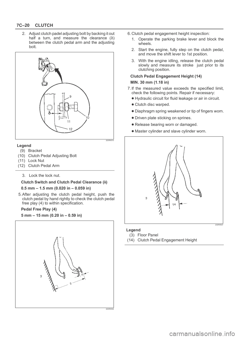
2. Adjust clutch padel adjusting bolt by backing it out
half a turn, and measure the clearance (
)
between the clutch pedal arm and the adjusting
bolt.
203RW010
Legend
(9) Bracket
(10) Clutch Pedal Adjusting Bolt
(11) Lock Nut
(12) Clutch Pedal Arm
3. Lock the lock nut.
Clutch Switch and Clutch Pedal Clearance (
)
0.5 mm – 1.5 mm (0.020 in – 0.059 in)
5. After adjusting the clutch pedal height, push the
clutch pedal by hand rightly to check the clutch pedal
free play (4) to within specification.
Pedal Free Play (4)
5 mm – 15 mm (0.20 in – 0.59 in)
203RW004
6. Clutch pedal engagement height inspection:
1. Operate the parking brake lever and block the
wheels.
2. Start the engine, fully step on the clutch pedal,
and move the shift lever to 1st position.
3. With the engine idling, release the clutch pedal
slowly and measure its stroke just prior to its
clutching position.
Clutch Pedal Engagement Height (14)
MIN. 30 mm (1.18 in)
7. If the measured value exceeds the specified limit,
check the following points. Repair if necessary:
Hydraulic circuit for fluid leakage or air in circuit.
Clutch disc warped.
Diaphragm spring weakened or tip of fingers worn.
Driven plate sticking on sprines.
Release bearing worn or damaged.
Master cylinder and slave cylinder worn.
203RW007
Legend
(3) Floor Panel
(14) Clutch Pedal Engagement Height