engine overheat OPEL FRONTERA 1998 User Guide
[x] Cancel search | Manufacturer: OPEL, Model Year: 1998, Model line: FRONTERA, Model: OPEL FRONTERA 1998Pages: 6000, PDF Size: 97 MB
Page 1467 of 6000

6E–350
ENGINE DRIVEABILITY AND EMISSIONS
to the intake manifold through an orifice with a PCM
controlled pintle. During operation, the PCM controls
pintle position by monitoring the pintle position feedback
signal. The feedback signal can be monitored with Tech 2
as “Actual EGR Pos.” “Actual EGR Pos.” should always
be near the commanded EGR position (”Desired EGR
Pos.”). If a problem with the EGR system will not allow the
PCM to control the pintle position properly, DTC P1406
will set. The PCM also tests for EGR flow. If incorrect flow
is detected, DTC P0401 will set. If DTCs P0401 and/or
P1406 are set, refer to the DTC charts.
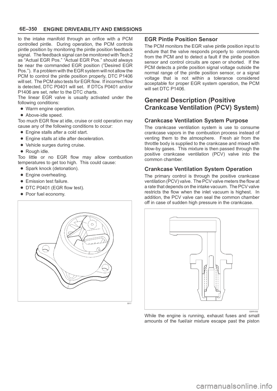
The linear EGR valve is usually activated under the
following conditions:
Warm engine operation.
Above-idle speed.
Too much EGR flow at idle, cruise or cold operation may
cause any of the following conditions to occur:
Engine stalls after a cold start.
Engine stalls at idle after deceleration.
Vehicle surges during cruise.
Rough idle.
Too little or no EGR flow may allow combustion
temperatures to get too high. This could cause:
Spark knock (detonation).
Engine overheating.
Emission test failure.
DTC P0401 (EGR flow test).
Poor fuel economy.
0017
EGR Pintle Position Sensor
The PCM monitors the EGR valve pintle position input to
endure that the valve responds properly to commands
from the PCM and to detect a fault if the pintle position
sensor and control circuits are open or shorted. If the
PCM detects a pintle position signal voltage outside the
normal range of the pintle position sensor, or a signal
voltage that is not within a tolerance considered
acceptable for proper EGR system operation, the PCM
will set DTC P1406.
General Description (Positive
Crankcase Ventilation (PCV) System)
Crankcase Ventilation System Purpose
The crankcase ventilation system is use to consume
crankcase vapors in the combustion process instead of
venting them to the atmosphere. Fresh air from the
throttle body is supplied to the crankcase and mixed with
blow-by gases. This mixture is then passed through the
positive crankcase ventilation (PCV) valve into the
common chamber.
Crankcase Ventilation System Operation
The primary control is through the positive crankcase
v e n t i l a t i o n ( P C V ) v a l v e . T h e PCV valve meters the flow at
a rate that depends on the intake vacuum. The PCV valve
restricts the flow when the inlet vacuum is highest. In
addition, the PCV valve can seal the common chamber
off in case of sudden high pressure in the crankcase.
028RV002
While the engine is running, exhaust fuses and small
amounts of the fuel/air mixture escape past the piston
Page 1474 of 6000

6F–3 ENGINE EXHAUST
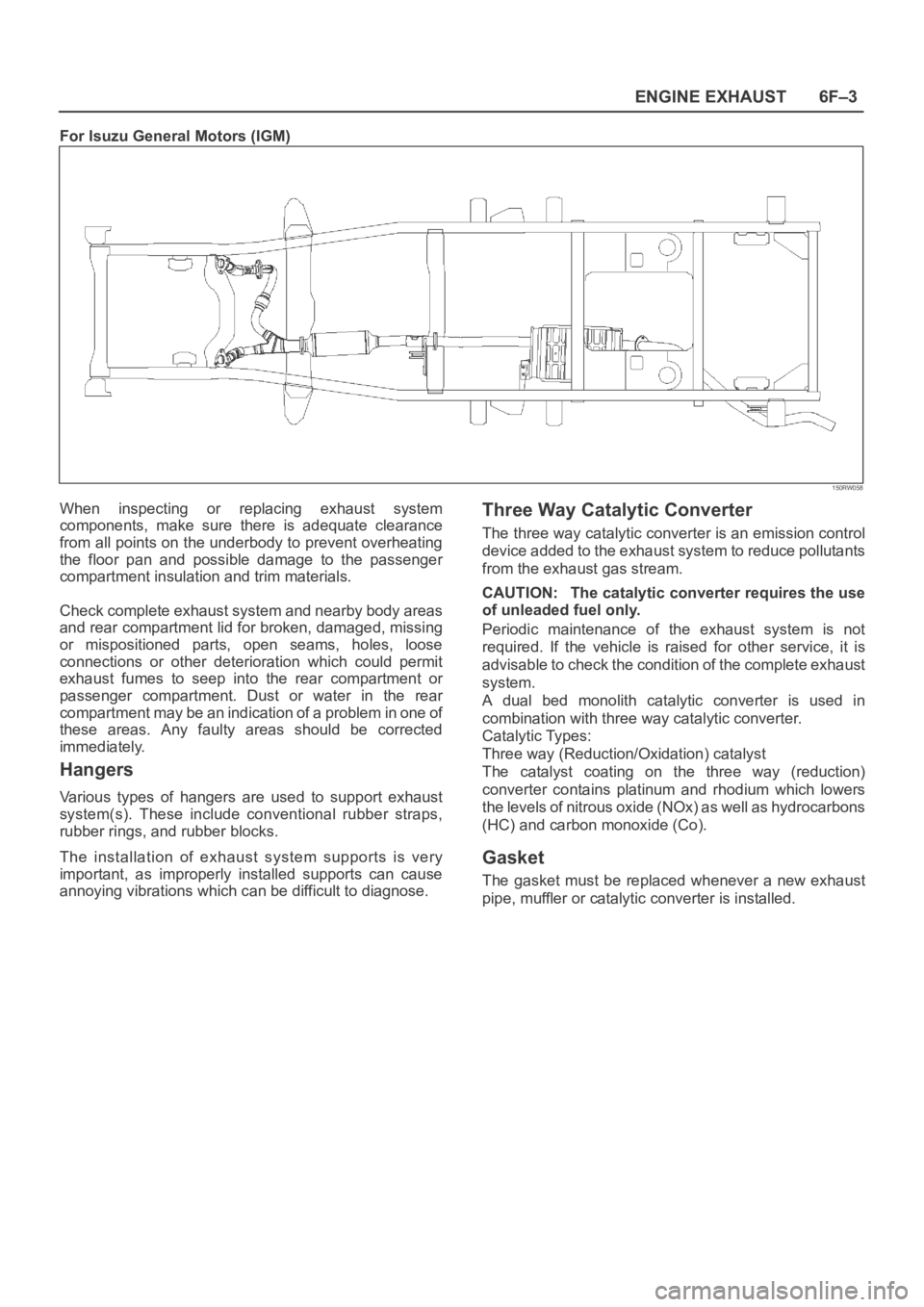
For Isuzu General Motors (IGM)
150RW058
When inspecting or replacing exhaust system
components, make sure there is adequate clearance
from all points on the underbody to prevent overheating
the floor pan and possible damage to the passenger
compartment insulation and trim materials.
Check complete exhaust system and nearby body areas
and rear compartment lid for broken, damaged, missing
or mispositioned parts, open seams, holes, loose
connections or other deterioration which could permit
exhaust fumes to seep into the rear compartment or
passenger compartment. Dust or water in the rear
compartment may be an indication of a problem in one of
these areas. Any faulty areas should be corrected
immediately.
Hangers
Various types of hangers are used to support exhaust
system(s). These include conventional rubber straps,
rubber rings, and rubber blocks.
The installation of exhaust system supports is very
important, as improperly installed supports can cause
annoying vibrations which can be difficult to diagnose.
Three Way Catalytic Converter
The three way catalytic converter is an emission control
device added to the exhaust system to reduce pollutants
from the exhaust gas stream.
CAUTION: The catalytic converter requires the use
of unleaded fuel only.
Periodic maintenance of the exhaust system is not
required. If the vehicle is raised for other service, it is
advisable to check the condition of the complete exhaust
system.
A dual bed monolith catalytic converter is used in
combination with three way catalytic converter.
Catalytic Types:
Three way (Reduction/Oxidation) catalyst
The catalyst coating on the three way (reduction)
converter contains platinum and rhodium which lowers
the levels of nitrous oxide (NOx) as well as hydrocarbons
(HC) and carbon monoxide (Co).
Gasket
The gasket must be replaced whenever a new exhaust
pipe, muffler or catalytic converter is installed.
Page 1838 of 6000

ENGINE COOLING 6B – 5
ENGINE COOLANT CHANGE
PROCEDURE
1. To change engine coolant, make sure that the
engine is cool.
WARNING:
When the coolant is heated to a high temperature,
be sure not to loosen or remove the radiator cap.
Otherwise you might get scalded by hot vapor or
boiling water. To open the radiator cap, put a piece
of thick cloth on the cap and loosen the cap slowly
to reduce the pressure once the coolant has
become cooler.
2. Open radiator cap and drain the cooling system by
loosening the drain valve on the radiator and on the
cylinder body.
NOTE: For best results it is suggested that the engine
cooling system be flushed at least once a year. It is
advisable to flush the interior of the cooling system
including the radiator before using anti-freeze
(ethylene-glycol based).
Replace damaged rubber hoses as the engine anti-
freeze coolant is liable to leak out even minor cracks.
Isuzu recommends using Isuzu genuine anti-freeze
(ethylene-glycol based) or equivalent, for the cooling
system and not add any inhibitors or additives.
CAUTION:
A failure to correctly fill the engine cooling system
in changing or topping off coolant may sometimes
cause the coolant to overflow from the filler neck
even before the engine and radiator are completely
full.
If the engine runs under this condition, shortage of
coolant may possibly result in engine overheating.
To avoid such trouble, the following precautions
should be taken in filling the system.
3. To refill engine coolant, pour coolant up to filler neck
using a filling hose which is smaller in outside
diameter than the filler neck. Otherwise air between
the filler neck and the filling hose will block entry,
preventing the system from completely filling up.
4. Keep a filling rate of 9 liter/min. or less. Filling over
this maximum rate may force air inside the engine
and radiator.
And also, the coolant overflow will increase, making
it difficult to determine whether or not the system is
completely full.
5. After filling the system full, pull out the filling hose
and check to see if air trapped in the system is
dislodged and the coolant level goes down. Should
the coolant level go down, repeat topping-off until
there is no more drop in the coolant level.
6. Directly after filling the radiator, fill the reservoir to
the maximum level.
7. Install and tighten radiator cap and start the engine.
After idling for 2 to 3 minutes, stop the engine and
reopen radiator cap. If the water level is lower,
replenish.WARNING:
When the coolant is heated to a high temperature,
be sure not to loosen or remove the radiator cap.
Otherwise you might get scalded by hot vapor or
boiling water. To open the radiator cap, put a piece
of thick cloth on the cap and loosen the cap slowly
to reduce the pressure once the coolant has
become cooler.
8. After tightening radiator cap, warm up the engine at
about 2,000 rpm.
Set heater adjustment to the highest temperature
position, and let the coolant circulate also into
heater water system.
9. Check to see the thermostat has opened by the
needle position of a water thermometer, conduct a
5-minute idle again and stop the engine.
10. When the engine has been cooled, check filler neck
for water level and replenish if required. Should
extreme shortage of coolant be found, check the
coolant system and reservoir tank hose for leakage.
11. Fill the coolant into the reservoir tank up to “MAX”
line.
Page 1842 of 6000

ENGINE COOLING 6B – 9
RADIATOR
REMOVAL
1. Disconnect battery ground cable
2. Loosen drain plug to drain coolant.
3. Radiator Hose
1) Disconnect lower hose and upper hose from the
engine.
4. Fan Guide
1) Remove clips on both sides and the bottom lock.
5. Reservoir Tank Hose
1) Disconnect the hose from radiator.
6. Bracket
7. Radiator Assembly
1) Remove the radiator assembly upward by the
hoses taking care not to damage the radiator
core by the fan blade.
2) Remove rubber cushions on both sides of the
bottom.
INSPECTION
Radiator Cap
1) Measure the valve opening pressure with the
radiator cap tester. Replace the radiator cap if it
exceeds the standard.
Valve opening pressure: 93.2 – 122.7 kPa
(0.95 – 1.25 kg/cm
2/
13.5 – 17.8 psi)
Check the condition of the negative pressure valve in
the center of the valve seat side of the cap. If the valve
seat does not move smoothly due to rust or dust, clean
and replace the radiator cap.Radiator Core
1) Deformed radiator fins could reduce radiation
effects, resulting in overheating. Straighten the fins.
In such a case, take care not to damage the fin
roots.
2) Remove dust and other foreign materials.
Flushing the Radiator
1) Wash the inside of radiator and the coolant
passage with water and a neutral detergent.
Remove all scales and rust.
110RW017
110RS006
Page 2124 of 6000

ENGINE EXHAUST 6F – 1
ENGINE EXHAUST
CONTENTS
CAUTION: Exhaust system components must have
enough clearance from the underbody to prevent
overheating of the floor pan and possible damage to the passenger compartment, insulation and trim
materials.
General Description . . . . . . . . . . . . . . . . . . 6F–2
Hangers . . . . . . . . . . . . . . . . . . . . . . . . . 6F–2
Gasket . . . . . . . . . . . . . . . . . . . . . . . . . . 6F–2
On-Vehicle Service . . . . . . . . . . . . . . . . . . . 6F–3
Front Exhaust Pipe . . . . . . . . . . . . . . . . . 6F–3Center Exhaust Pipe . . . . . . . . . . . . . . . . 6F–5
Exhaust Silencer . . . . . . . . . . . . . . . . . . . 6F–6
Rear Exhaust Pipe . . . . . . . . . . . . . . . . . 6F–7
Page 2125 of 6000

6F – 2 ENGINE EXHAUST
GENERAL DESCRIPTION
150RW070
When inspecting or replacing exhaust system
components, make sure there is adequate clearance
from all points on the underbody to prevent overheating
of the floor pan and possible damage to the passenger
compartment insulation and trim materials.
Check complete exhaust system and nearby body
areas and rear compartment lid for broken, damaged,
missing or mispositioned parts, open seams, holes
loose connections or other deterioration which could
permit exhaust fumes to seep into the rear
compartment or passenger compartment. Dust or water
in the rear compartment may be an indication of a
problem in one of these areas. Any faulty areas should
be corrected immediately.HANGERS
Various types of hangers are used to support exhaust
system(s). These include conventional rubber straps,
rubber rings, and rubber blocks.
The installation of exhaust system supports is very
important, as improperly installed supports can cause
annoying vibrations which can be difficult to diagnose.
GASKET
The gasket must be replaced whenever a new exhaust
pipe, muffler or exhaust throttle is installed.
Page 4507 of 6000

6A–11
ENGINE MECHANICAL
Condition CorrectionPossible cause
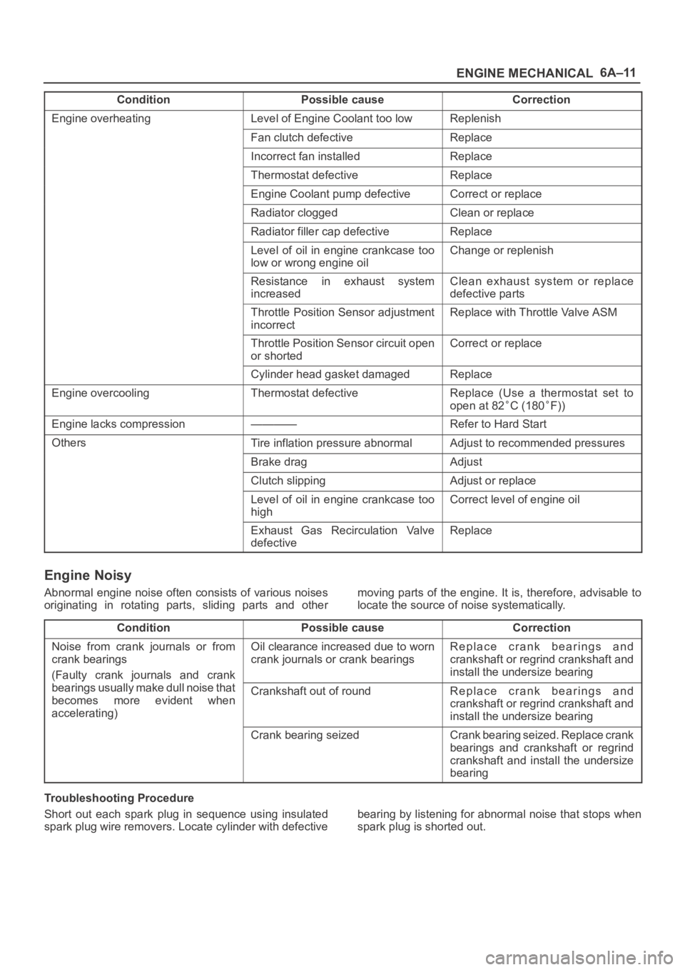
Engine overheatingLevel of Engine Coolant too lowReplenish
Fan clutch defectiveReplace
Incorrect fan installedReplace
Thermostat defectiveReplace
Engine Coolant pump defectiveCorrect or replace
Radiator cloggedClean or replace
Radiator filler cap defectiveReplace
Level of oil in engine crankcase too
low or wrong engine oilChange or replenish
Resistance in exhaust system
increasedClean exhaust system or replace
defective parts
Throttle Position Sensor adjustment
incorrectReplace with Throttle Valve ASM
Throttle Position Sensor circuit open
or shortedCorrect or replace
Cylinder head gasket damagedReplace
Engine overcoolingThermostat defectiveReplace (Use a thermostat set to
open at 82
C (180F))
Engine lacks compression————Refer to Hard Start
OthersTire inflation pressure abnormalAdjust to recommended pressures
Brake dragAdjust
Clutch slippingAdjust or replace
Level of oil in engine crankcase too
highCorrect level of engine oil
Exhaust Gas Recirculation Valve
defectiveReplace
Engine Noisy
Abnormal engine noise often consists of various noises
originating in rotating parts, sliding parts and othermoving parts of the engine. It is, therefore, advisable to
locate the source of noise systematically.
Condition
Possible causeCorrection
Noise from crank journals or from
crank bearings
(Faulty crank journals and crankOil clearance increased due to worn
crank journals or crank bearingsReplace crank bearings and
crankshaft or regrind crankshaft and
install the undersize bearing
yj
bearings usually make dull noise that
becomes more evident when
accelerating)Crankshaft out of roundReplace crank bearings and
crankshaft or regrind crankshaft and
install the undersize bearing
Crank bearing seizedCrank bearing seized. Replace crank
bearings and crankshaft or regrind
crankshaft and install the undersize
bearing
Troubleshooting Procedure
Short out each spark plug in sequence using insulated
spark plug wire removers. Locate cylinder with defectivebearing by listening for abnormal noise that stops when
spark plug is shorted out.
Page 4509 of 6000

6A–13
ENGINE MECHANICAL
Condition CorrectionPossible cause
Engine knockingPreignition due to use of spark plugs
of inadequate heat rangeInstall Spark Plugs of adequate heat
range
Carbon deposits in combustion
chambersClean
Fuel too low in octane ratingReplace fuel
Wide Open Throttle enrichment
system failureRefer to Section 6E
Selection of transmission gear
incorrectCaution operator of incorrect gear
selection
Engine overheatingRefer to “Engine Lacks Power”
OthersWater pump defectiveReplace
Drive belt slippingReplace auto tentioner or drive belt
Abnormal Combustion
ConditionPossible causeCorrection
Trouble in fuel systemFuel pressure control valve defectiveReplace
Fuel filter cloggedReplace
Fuel pump cloggedClean or replace
Fuel tank or fuel pipe cloggedClean or replace
Fuel injector cloggedClean or replace
Fuel pump relay defectiveReplace
Power supply cable for fuel pump
broken or poor connectionsReconnect, correct or replace
Mass Airflow (MAF) sensor circuit
open or defectiveCorrect or replace
MAF Sensor defectiveReplace
Manifold Absolute Pressure Sensor
circuit open or shortedCorrect or replace
Manifold Absolute Pressure Sensor
defectiveReplace
Engine Coolant Temperature (ECT)
Sensor circuit open or shortedCorrect or replace
ECT Sensor defectiveReplace
Throttle Position Sensor adjustment
incorrectReadjust
Throttle Position Sensor defectiveReplace
Throttle Position Sensor connector
poor connectionsReconnect
Vehicle Speed Sensor cable poor
connections or defectiveCorrect or replace
Vehicle Speed Sensor loosely fixedFix tightly
Vehicle Speed Sensor in wrong
contact or defectiveReplace
Powertrain Control Module cable
poor connections or defectiveCorrect or replace
Page 4597 of 6000

6B–4
ENGINE COOLING
NOTE: Antifreeze solution + Water = Total cooling
system capacity.
Total Cooling System Capacity
M/T 8.8Lit (2.32Us gal)
A/T 8.4Lit (2.22Us gal)
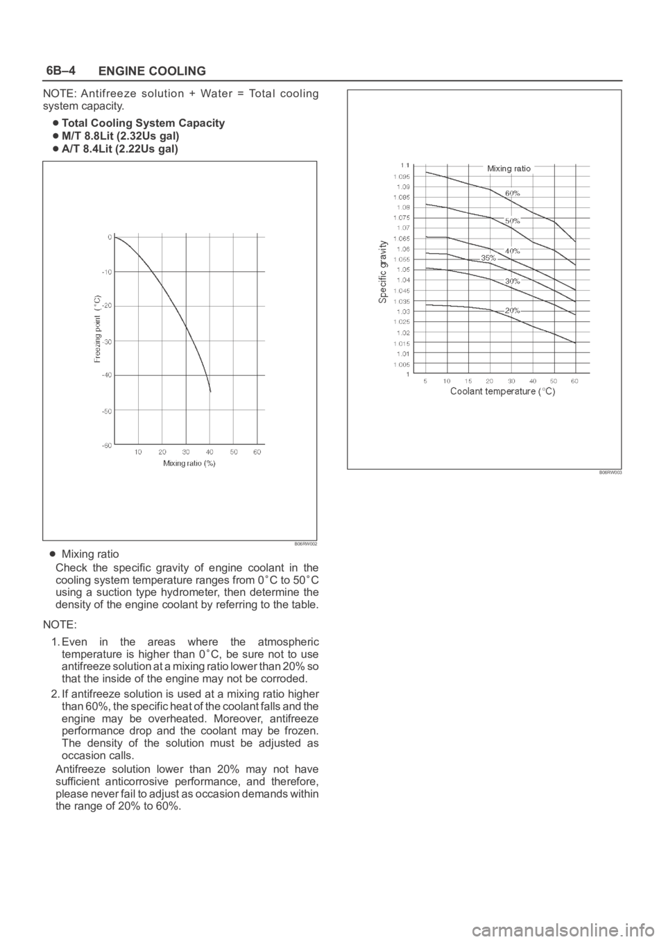
B06RW002
Mixing ratio
Check the specific gravity of engine coolant in the
cooling system temperature ranges from 0
C to 50C
using a suction type hydrometer, then determine the
density of the engine coolant by referring to the table.
NOTE:
1. Even in the areas where the atmospheric
temperature is higher than 0
C, be sure not to use
antifreeze solution at a mixing ratio lower than 20% so
that the inside of the engine may not be corroded.
2. If antifreeze solution is used at a mixing ratio higher
than 60%, the specific heat of the coolant falls and the
engine may be overheated. Moreover, antifreeze
performance drop and the coolant may be frozen.
The density of the solution must be adjusted as
occasion calls.
Antifreeze solution lower than 20% may not have
sufficient anticorrosive performance, and therefore,
please never fail to adjust as occasion demands within
the range of 20% to 60%.
B06RW003
Page 4598 of 6000

ENGINE COOLING6B–5
Diagnosis
Engine Cooling Trouble
ConditionPossible causeCorrection
Engine overheatingLow Engine Coolant levelReplenish
Incorrect fan installedReplace
Thermo meter unit faultyReplace
Faulty thermostatReplace
Faulty Engine Coolant temperature
sensorRepair or replace
Clogged radiatorClean or replace
Faulty radiator capReplace
Low engine oil level or use of
improper engine oilReplenish or change oil
Clogged exhaust systemClean exhaust system or replace
faulty parts
Faulty Throttle Position sensorReplace throttle valve assembly
Open or shorted Throttle Position
sensor circuitRepair or replace
Damaged cylinder head gasketReplace
Engine overcoolingFaulty thermostatReplace
Engine slow to warm–upFaulty thermostatReplace
Thermo unit faultyReplace