radio OPEL FRONTERA 1998 User Guide
[x] Cancel search | Manufacturer: OPEL, Model Year: 1998, Model line: FRONTERA, Model: OPEL FRONTERA 1998Pages: 6000, PDF Size: 97 MB
Page 3247 of 6000

8F–52BODY STRUCTURE
13. Remove meter assembly.
Remove the 4 meter assembly fixing screws and
disconnect the meter harness connectors.
821RS034
14. Remove control lever assembly.
Refer to HVAC System in HVAC section.
15. Remove radio assembly.
Remove 2 fixing screws.
16. Remove vent duct assembly.
Remove 5 fixing screws.
17. Remove instrument harness assembly.
Remove the 4 fixing screws, fasteners at the 4
positions and the clips at the 7 positions.
18. Remove side defroster grille.
NOTE: For the order of removal steps in which each
items contained in the instrument panel assembly are
removed individually, refer to the chart.
Page 3248 of 6000

8F–53 BODY STRUCTURE
Installation
To install, follow the removal steps in the reverse order.
Order Of Removal/Installation Steps For Each Item
Removal Item
Removal ProcedureRemoval Step
Front console assem-
blyShift knob (M/T), Power & Winter SW (A/T), Transfer knob, Seat
heater/Miller SW conn. and 4 screws1, 2
Lower cluster assem-
bly3 screws, Ciger lighter conn. and Ashtray illumination conn.13
Glove box2 screws4
Instrument panel pas-
senger lower cover7 screws and 1 clip15
Passenger knee bol-
ster reinforcement4 nuts and 4 bolts16
Instrument panel driver
lower coverEngine hood opening fixing screw, 2 screws, 1 bolt, 1 clip and fasten-
ers at 4 positions13, 7
Driver knee bolster6 nuts13, 7, 8
Front defroster grilleClaws at 8 positions9
Instrument panel as-
sembly2 bolts (SRS adjust bracket cross beam), A/C control cable (Unit
side at 3 position), Instrument harness connector (Driver side 5 posi-
tion, assist side 3 position), SRS module conn., Radio antenna jack,
Earth cable, 9 bolts and 3 nuts110
Passenger inflator
module4 nuts (SRS moduleInstrument panel), 2 nuts 0 and 2 washers
(SRS module
support bracket) and 2 clips
16, 11
Instrument panel clus-
ter5 Screws, fastener at 4 position and each SW conn.13, 7, 12
Meter assembly4 screws and connectors13, 7, 12, 13
A/C control panel as-
sembly4 screws and connectors13, 7, 12, 14
Radio assembly2 screws13, 15
Vent duct assembly5 screws110, 16
Instrument harness as-
sembly4 screws, fasteners at 4 position, and clips at 7 position110, 17
Side defroster grille18
M/T = Manual Transmission
A/T = Automatic Transmission
SRS = Supplemental Restraint System
A/C = Air Conditioning
Page 4699 of 6000

6E–42
ENGINE DRIVEABILITY AND EMISSIONS
Intermittent Malfunction Indicator Lamp
In the case of an “intermittent” fault, the MIL (“Check
Engine” lamp) may illuminate and then (after three trips)
go “OFF”. However, the corresponding diagnostic trouble
code will be stored in the memory. When unexpected
diagnostic trouble codes appear, check for an intermittent
malfunction.
A diagnostic trouble code may reset. Consult the
“Diagnostic Aids” associated with the diagnostic trouble
code. A physical inspection of the applicable sub-system
most often will resolve the problem.
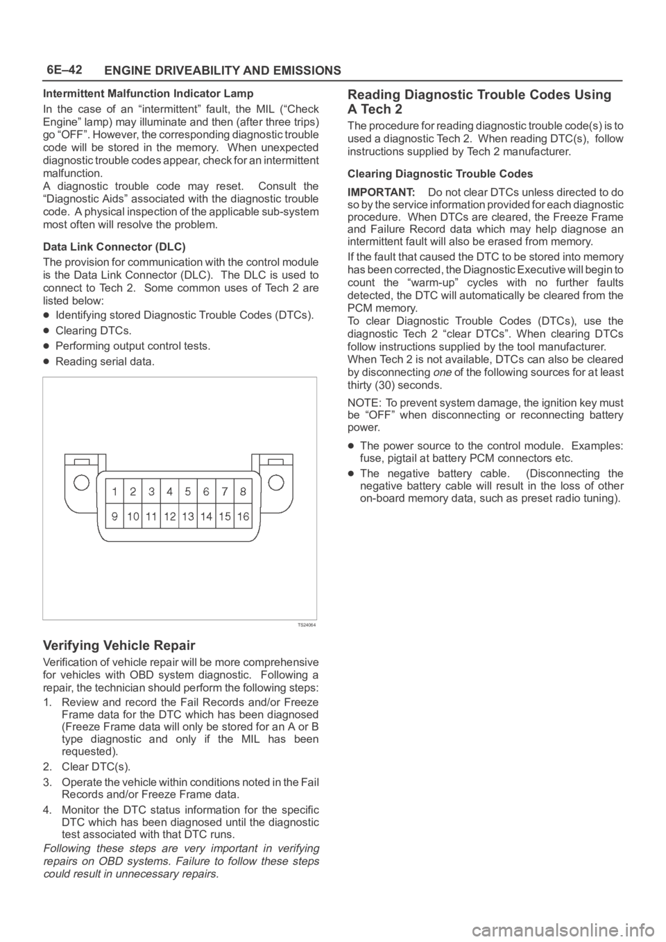
Data Link Connector (DLC)
The provision for communication with the control module
is the Data Link Connector (DLC). The DLC is used to
connect to Tech 2. Some common uses of Tech 2 are
listed below:
Identifying stored Diagnostic Trouble Codes (DTCs).
Clearing DTCs.
Performing output control tests.
Reading serial data.
TS24064
Verifying Vehicle Repair
Verification of vehicle repair will be more comprehensive
for vehicles with OBD system diagnostic. Following a
repair, the technician should perform the following steps:
1. Review and record the Fail Records and/or Freeze
Frame data for the DTC which has been diagnosed
(Freeze Frame data will only be stored for an A or B
type diagnostic and only if the MIL has been
requested).
2. Clear DTC(s).
3. Operate the vehicle within conditions noted in the Fail
Records and/or Freeze Frame data.
4. Monitor the DTC status information for the specific
DTC which has been diagnosed until the diagnostic
test associated with that DTC runs.
Following these steps are very important in verifying
repairs on OBD systems. Failure to follow these steps
could result in unnecessary repairs.
Reading Diagnostic Trouble Codes Using
A Tech 2
The procedure for reading diagnostic trouble code(s) is to
used a diagnostic Tech 2. When reading DTC(s), follow
instructions supplied by Tech 2 manufacturer.
Clearing Diagnostic Trouble Codes
IMPORTANT:Do not clear DTCs unless directed to do
so by the service information provided for each diagnostic
procedure. When DTCs are cleared, the Freeze Frame
and Failure Record data which may help diagnose an
intermittent fault will also be erased from memory.
If the fault that caused the DTC to be stored into memory
has been corrected, the Diagnostic Executive will begin to
count the “warm-up” cycles with no further faults
detected, the DTC will automatically be cleared from the
PCM memory.
To clear Diagnostic Trouble Codes (DTCs), use the
diagnostic Tech 2 “clear DTCs”. When clearing DTCs
follow instructions supplied by the tool manufacturer.
When Tech 2 is not available, DTCs can also be cleared
by disconnecting
one of the following sources for at least
thirty (30) seconds.
NOTE: To prevent system damage, the ignition key must
be “OFF” when disconnecting or reconnecting battery
power.
The power source to the control module. Examples:
fuse, pigtail at battery PCM connectors etc.
The negative battery cable. (Disconnecting the
negative battery cable will result in the loss of other
on-board memory data, such as preset radio tuning).
Page 4997 of 6000

6E–340
ENGINE DRIVEABILITY AND EMISSIONS
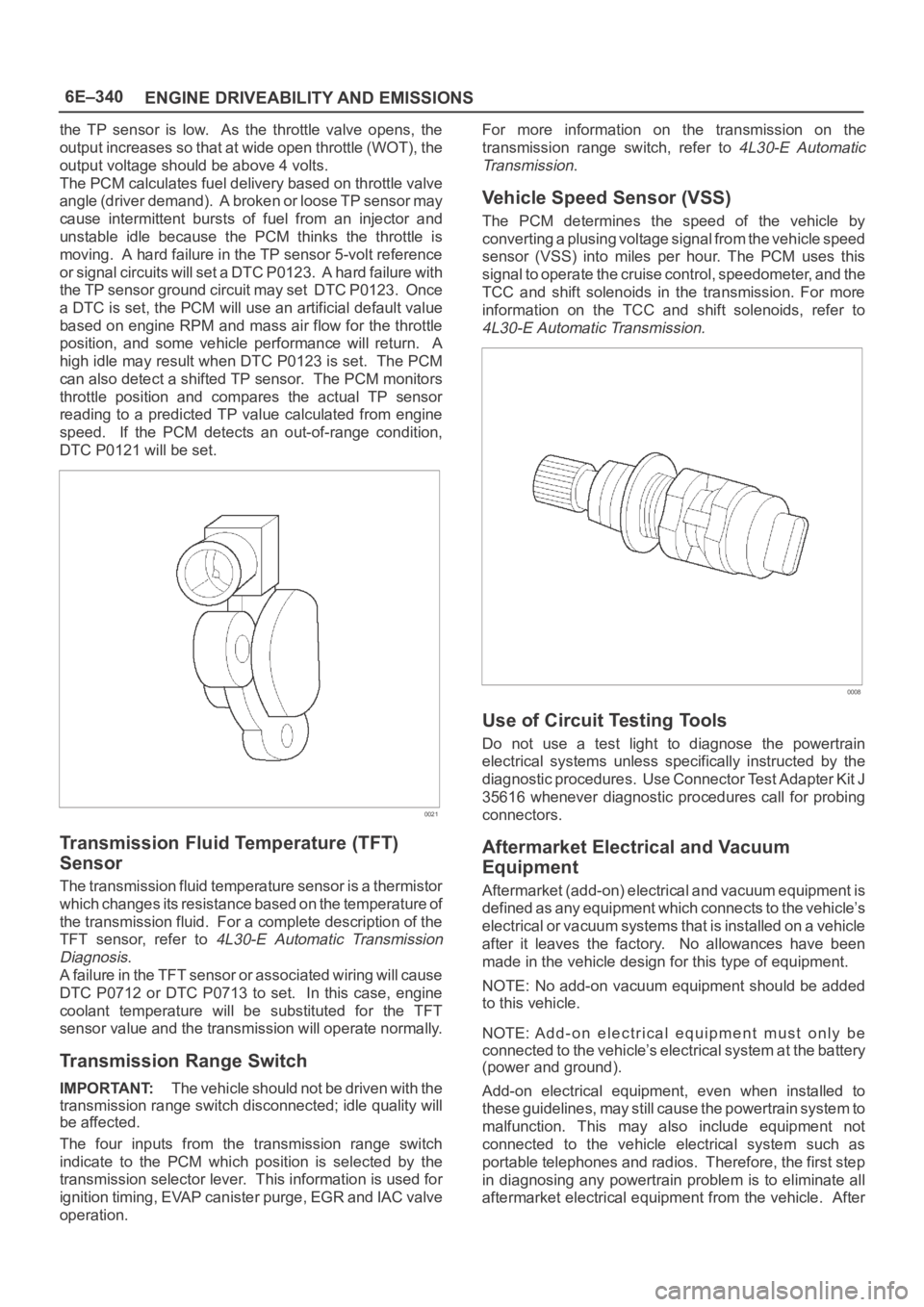
the TP sensor is low. As the throttle valve opens, the
output increases so that at wide open throttle (WOT), the
output voltage should be above 4 volts.
The PCM calculates fuel delivery based on throttle valve
angle (driver demand). A broken or loose TP sensor may
cause intermittent bursts of fuel from an injector and
unstable idle because the PCM thinks the throttle is
moving. A hard failure in the TP sensor 5-volt reference
or signal circuits will set a DTC P0123. A hard failure with
the TP sensor ground circuit may set DTC P0123. Once
a DTC is set, the PCM will use an artificial default value
based on engine RPM and mass air flow for the throttle
position, and some vehicle performance will return. A
high idle may result when DTC P0123 is set. The PCM
can also detect a shifted TP sensor. The PCM monitors
throttle position and compares the actual TP sensor
reading to a predicted TP value calculated from engine
speed. If the PCM detects an out-of-range condition,
DTC P0121 will be set.
0021
Transmission Fluid Temperature (TFT)
Sensor
The transmission fluid temperature sensor is a thermistor
which changes its resistance based on the temperature of
the transmission fluid. For a complete description of the
TFT sensor, refer to
4L30-E Automatic Transmission
Diagnosis
.
A failure in the TFT sensor or associated wiring will cause
DTC P0712 or DTC P0713 to set. In this case, engine
coolant temperature will be substituted for the TFT
sensor value and the transmission will operate normally.
Transmission Range Switch
IMPORTANT:The vehicle should not be driven with the
transmission range switch disconnected; idle quality will
be affected.
The four inputs from the transmission range switch
indicate to the PCM which position is selected by the
transmission selector lever. This information is used for
ignition timing, EVAP canister purge, EGR and IAC valve
operation.For more information on the transmission on the
transmission range switch, refer to
4L30-E Automatic
Transmission
.
Vehicle Speed Sensor (VSS)
The PCM determines the speed of the vehicle by
converting a plusing voltage signal from the vehicle speed
sensor (VSS) into miles per hour. The PCM uses this
signal to operate the cruise control, speedometer, and the
TCC and shift solenoids in the transmission. For more
information on the TCC and shift solenoids, refer to
4L30-E Automatic Transmission.
0008
Use of Circuit Testing Tools
Do not use a test light to diagnose the powertrain
electrical systems unless specifically instructed by the
diagnostic procedures. Use Connector Test Adapter Kit J
35616 whenever diagnostic procedures call for probing
connectors.
Aftermarket Electrical and Vacuum
Equipment
Aftermarket (add-on) electrical and vacuum equipment is
defined as any equipment which connects to the vehicle’s
electrical or vacuum systems that is installed on a vehicle
after it leaves the factory. No allowances have been
made in the vehicle design for this type of equipment.
NOTE: No add-on vacuum equipment should be added
to this vehicle.
NOTE: Add-on electrical equipment must only be
connected to the vehicle’s electrical system at the battery
(power and ground).
Add-on electrical equipment, even when installed to
these guidelines, may still cause the powertrain system to
malfunction. This may also include equipment not
connected to the vehicle electrical system such as
portable telephones and radios. Therefore, the first step
in diagnosing any powertrain problem is to eliminate all
aftermarket electrical equipment from the vehicle. After
Page 5457 of 6000

6E–28
4JX1–TC ENGINE DRIVEABILITY AND EMISSIONS
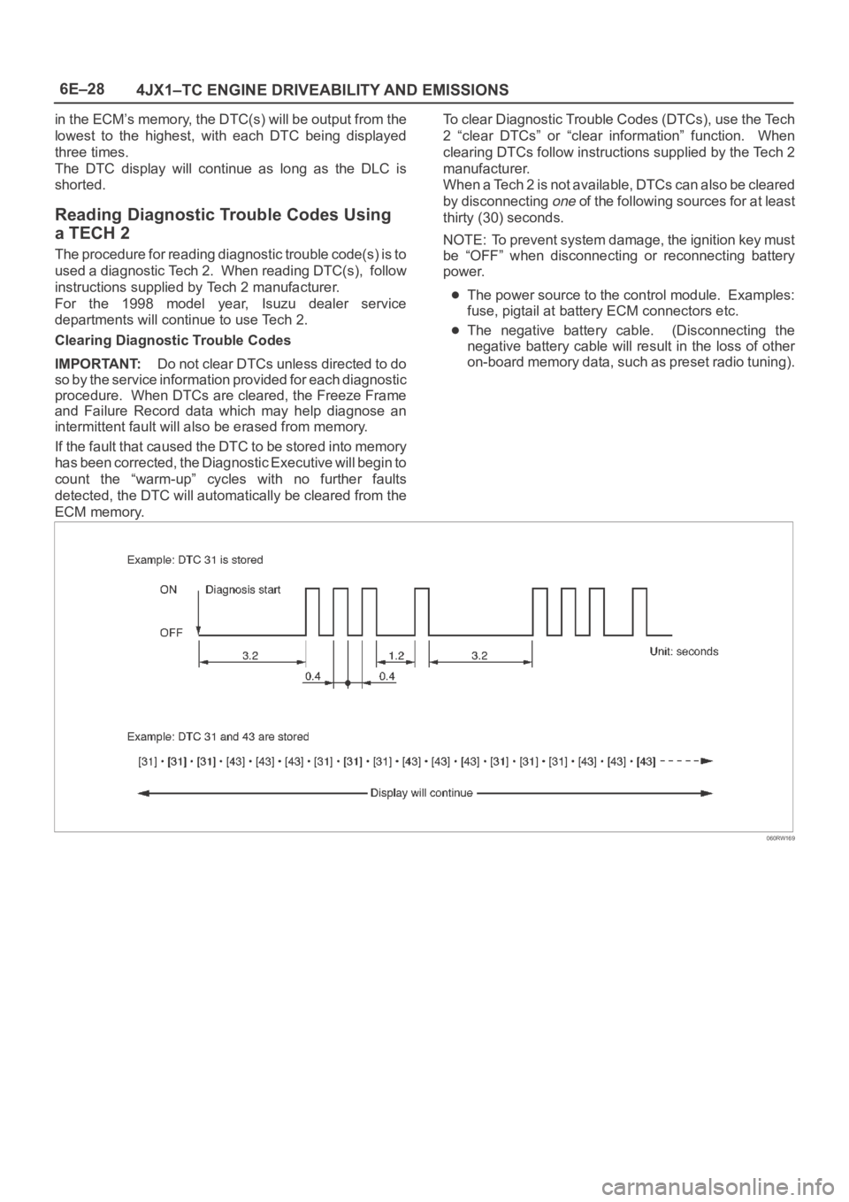
in the ECM’s memory, the DTC(s) will be output from the
lowest to the highest, with each DTC being displayed
three times.
The DTC display will continue as long as the DLC is
shorted.
Reading Diagnostic Trouble Codes Using
a TECH 2
The procedure for reading diagnostic trouble code(s) is to
used a diagnostic Tech 2. When reading DTC(s), follow
instructions supplied by Tech 2 manufacturer.
For the 1998 model year, Isuzu dealer service
departments will continue to use Tech 2.
Clearing Diagnostic Trouble Codes
IMPORTANT:Do not clear DTCs unless directed to do
so by the service information provided for each diagnostic
procedure. When DTCs are cleared, the Freeze Frame
and Failure Record data which may help diagnose an
intermittent fault will also be erased from memory.
If the fault that caused the DTC to be stored into memory
has been corrected, the Diagnostic Executive will begin to
count the “warm-up” cycles with no further faults
detected, the DTC will automatically be cleared from the
ECM memory.To clear Diagnostic Trouble Codes (DTCs), use the Tech
2 “clear DTCs” or “clear information” function. When
clearing DTCs follow instructions supplied by the Tech 2
manufacturer.
When a Tech 2 is not available, DTCs can also be cleared
by disconnecting
one of the following sources for at least
thirty (30) seconds.
NOTE: To prevent system damage, the ignition key must
be “OFF” when disconnecting or reconnecting battery
power.
The power source to the control module. Examples:
fuse, pigtail at battery ECM connectors etc.
The negative battery cable. (Disconnecting the
negative battery cable will result in the loss of other
on-board memory data, such as preset radio tuning).
060RW169
Page 5656 of 6000

6E–227 4JX1–TC ENGINE DRIVEABILITY AND EMISSIONS
QOS
Diagnostics
– Malfunction Indicator Lamp (Service Engine
Soon lamp)
– Data Link Connector (DLC)
– Data Output
ECM Service Precautions
The ECM is designed to withstand normal current draws
associated with vehicle operation. Avoid overloading any
circuit. When testing for opens and shorts, do not ground
or apply voltage to any of the ECM’s circuits unless
instructed to do so. These circuits should only be tested
using digital voltmeter. The ECM should remain
connected to the ECM or to a recommended breakout
box.
Intake Throttle Position (ITP) Sensor
ITP sensor is a potentiometer type and installed to the
intake throttle valve body. A voltage of 5V is applied
constantly from ECM to ITP sensor thereby to determine
by change in voltage the opening of the intake throttle
valve during warming up.
Transmission Range Switch
IMPORTANT:The vehicle should not be driven with the
transmission range switch disconnected; idle quality will
be affected.
The four inputs from the transmission range switch
indicate to the ECM which position is selected by the
transmission selector lever.
For more information on the transmission on the
transmission range switch, refer to
Automatic
Tr a n s m i s s i o n
.
Accelerator Position Sensor (AP)
AP sensor is a potentiometer type and installed to
accelerator pedal bracket. A voltage of 5V constantly
applied from ECM to the sensor thereby to determine the
accelerator pedaling angle by change in voltage. Further,
this sensor is provided with an accelerator switch, which
is set off only when the accelerator pedal is stepped on.
Aftermarket Electrical and Vacuum
Equipment
Aftermarket (add-on) electrical and vacuum equipment is
defined as any equipment which connects to the vehicle’s
electrical or vacuum systems that is installed on a vehicle
after it leaves the factory. No allowances have been
made in the vehicle design for this type of equipment.
NOTE: No add-on vacuum equipment should be added
to this vehicle.
NOTE: Add-on electrical equipment must only be
connected to the vehicle’s electrical system at the battery
(power and ground).
Add-on electrical equipment, even when installed to
these guidelines, may still cause the powertrain system to
malfunction. This may also include equipment not
connected to the vehicle electrical system such asportable telephones and radios. Therefore, the first step
in diagnosing any powertrain problem is to eliminate all
aftermarket electrical equipment from the vehicle. After
this is done, if the problem still exists, it may be diagnosed
in the normal manner.
Electrostatic Discharge Damage
Electronic components used in the ECM are often
designed to carry very low voltage. Electronic
components are susceptible to damage caused by
electrostatic discharge. Less than 100 volts of static
electricity can cause damage to some electronic
components. By comparison, it takes as much as 4000
volts for a person to feel even the zap of a static
discharge.
TS23793
There are several ways for a person to become statically
charged. The most common methods of charging are by
friction and induction.
An example of charging by friction is a person sliding
across a vehicle seat.
Charge by induction occurs when a person with well
insulated shoes stands near a highly charged object
and momentary touches ground. Charges of the
same polarity are drained off leaving the person
highly charged with the opposite polarity. Static
charges can cause damage, therefore it is important
to use care when handling and testing electronic
components.
NOTE: To prevent possible electrostatic discharge
damage, follow these guidelines:
Do not touch the ECM connector pins or soldered
components on the ECM circuit board.
Do not open the replacement part package until the
part is ready to be installed.
Before removing the part from the package, ground
the package to a known good ground on the vehicle.
If the part has been handled while sliding across the
seat, while sitting down from a standing position, or
while walking a distance, touch a known good ground
before installing the part.
Page 5804 of 6000

AUTOMATIC TRANSMISSION (AW30-40LE) 7A–23
INTERMITTENT CONDITIONS
If the Tech2 displays a code as intermittent, or if after a
test drive a code does not reappear, the problem is most
likely a faulty electrical connection or loose wiring.
Terminals should always be the prime suspect.
Intermittent rarely occur in sophisticated electronic
components such as the Transmission Control Module
(TCM).
When an intermittent problem is encountered, check
suspect circuits for:
• Poor terminal to wire connection.
• Terminals not fully seated in the connector body
(backed out).
• Improperly formed or damaged terminals.
• Loose, dirty, or corroded ground connections.
HINT: Any time you have an intermittent in more than
one circuit, check whether the circuits share a
common ground connection.
• Pinched or damaged wires.
• Electro-Magnetic Interference (EMI)
HINT: Check that all wires are properly routed away
from spark plug wires, distributor wires, coil,
and generator. Also check for improperly
installed electrical options, such as lights, 2-
way radios, etc.
Use the F2: SNAPSHOT mode of the Tech2 to help
isolate the cause of an intermittent fault. The snapshot
mode will record information before and after the
problem occurs. Set the snapshot to "trigger" on the
suspect code (or codes) or, if you notice the repor ted
symptom during test drive, trigger the snapshot
manually.
After the snapshot has been triggered, command the
Tech2 to play back the flow of data recorded from each
of the various sensors. Signs of an intermittent fault in a
sensor circuit are a sudden unexplainable jump in data
values out of the normal range.