Seat OPEL FRONTERA 1998 Workshop Manual
[x] Cancel search | Manufacturer: OPEL, Model Year: 1998, Model line: FRONTERA, Model: OPEL FRONTERA 1998Pages: 6000, PDF Size: 97 MB
Page 3549 of 6000

RESTRAINT CONTROL SYSTEM 9J1–62
DTC 46 Driver Pretensioner Loop Short To Ignition
StepActionYe sNo
1Was the “SRS Diagnostic System Check” performed?
Go to Step 2
Go to the “SRS
Diagnostic
System Check”
21. When measurements are requested in this chart use
5–8840–0285–0 DVM with correct terminal adapter from
5–8840–0385–0.
Ignition switch “OFF.”
Connect scan tool data link connector. follow directions as
given in the scan tool operator’s manual.
2. Ignition switch “ON.”
3. Read driver belt sense LO .
Is driver belt sense LO more than 3.5 volts?
Go to Step 3Go to Chart A
31. Ignition switch “OFF.”
2. Disconnect driver pretensioner assembly yellow 2–pin
connector at the base of the driver seat, leave passenger
pretensioner assembly connected.
3. Connect SRS driver /passenger load tool 5–8840–2421–0 and
appropriate adapter to driver pretensioner assembly harness
connector.
4. Ignition switch “ON.”
Is DTC 46 current?
Go to Step 4
Ignition switch
“OFF”
Replace driver
pretensioner
assembly
Go to Step 6
41. Ignition switch “OFF.”
2. Disconnect SDM.
3. Disconnect SRS driver /passenger load tool.
4. Measure resistance on SDM harness connector “21” to
terminal “12” (ignition).
Does 5–8840–0285–0 display “OL” (infinite)?
Go to Step 5
Replace SRS
harness or repair
chassis harness
Go to Step 6
5Measure resistance on SDM harness connector from terminal
“22” to terminal “12” (ignition).
Does 5–8840–0285–0 display “OL” (infinite)?
Go to Chart A
Replace SRS
harness or repair
chassis harness
Go to Step 6
61. Reconnect all components ensure all component are properly
mounted.
2. Clear diagnostic trouble codes.
Was this step finished?
Go to the “SRS
Diagnostic
System Check”
Go to Step 6
Page 3550 of 6000

9J1–63
RESTRAINT CONTROL SYSTEM
DTC 52 Pretensioner Deployment Event Commanded
D09RW014
Circuit Description:
The SDM contains a sensing device which converts
vehicle velocity changes to an electrical signal. The
electrical signal generated is processed by the SDM and
then compared to a value stored in memory. When the
generated signal exceeds the stored value, the SDM will
cause current to flow through the pretensioner assembly
deploying the pretensioners and causing DTC 52 to set.
DTC Will Set When:
The SDM detects a frontal crash, up to 30 degrees off the
centerline of the vehicle, of sufficient force to warrant
deployment of the air bags and pretensioner seat belt.
Action Taken:
SDM turns “ON” the “AIR BAG” warning lamp records
“Crash Data”, and sets a diagnostic trouble code.
DTC Will Clear When:
The SDM is replaced.
DTC Chart Test Description:
Number(s) below refer to step number(s) on the
diagnostic chart:
2. If pretensioner assembly (s) has not deployed, DTC
52 may have falsely set.
3. If DTC 52 has set with no signs of frontal impact, the
diagnostic trouble code has falsely set.
Page 3569 of 6000
PAGE BACK PAGE NEXT
THIS MALUAL INCLUDES THE FOLLOWING SECTIONS:
SECTION No. CONTRNTS
8A LIGHTING SYSTEM
8B WIPER / WASHER SYSTEM
8C ENTERTAINMENT
8D WIRING SYSTEM
8E METER AND GAUGE
8F BODY STRUCTURE
8G SEATS
8H SECURITY AND LOCKS
8I SUN ROOF/CONVERTIBLE TOP
8J EXTERIOR / INTERIOR TRIM
HOME
8A
8B
8C
8D
8E
8F
8G
8H
8I
8J
Page 3570 of 6000

PAGE BACK PAGE NEXT
THIS MALUAL INCLUDES THE FOLLOWING SECTIONS:
SECTION No. CONTRNTS
9A SEAT BELT SYSTEM
9J SUPPLEMENTAL RESTRAINT SYSTEM
9J1 RESTRAINT CONTROL SYSTEM
HOME
9A
9J
9J1
Page 3780 of 6000
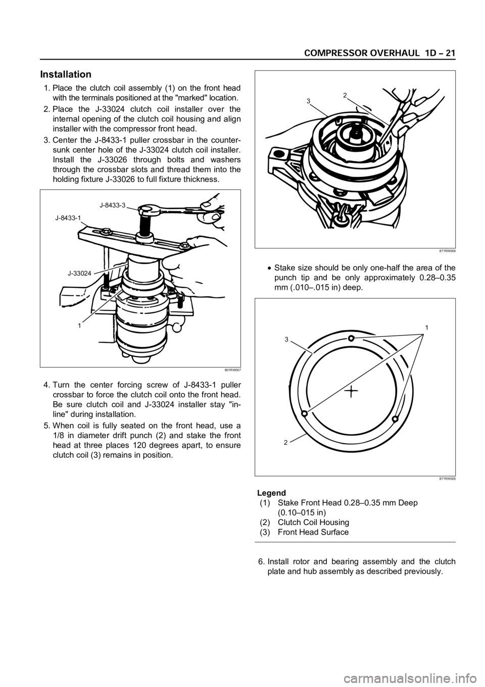
Installation
1. Place the clutch coil assembly (1) on the front head
with the terminals positioned at the "marked" location.
2. Place the J-33024 clutch coil installer over the
internal opening of the clutch coil housing and align
installer with the compressor front head.
3. Center the J-8433-1 puller crossbar in the counter-
sunk center hole of the J-33024 clutch coil installer.
Install the J-33026 through bolts and washers
through the crossbar slots and thread them into the
holding fixture J-33026 to full fixture thickness.
4. Turn the center forcing screw of J-8433-1 puller
crossbar to force the clutch coil onto the front head.
Be sure clutch coil and J-33024 installer stay "in-
line" during installation.
5. When coil is fully seated on the front head, use a
1/8 in diameter drift punch (2) and stake the front
head at three places 120 degrees apart, to ensure
clutch coil (3) remains in position.
Stake size should be only one-half the area of the
punch tip and be only approximately 0.28–0.35
mm (.010–.015 in) deep.
Legend
(1) Stake Front Head 0.28–0.35 mm Deep
(0.10–015 in)
(2) Clutch Coil Housing
(3) Front Head Surface
6. Install rotor and bearing assembly and the clutch
plate and hub assembly as described previously.
J-8433-3
J-8433-1
J-33024
1
901RW007
2
3
871RW004
1
23
871RW005
Page 3782 of 6000
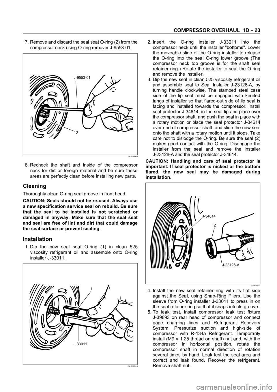
7. Remove and discard the seal seat O-ring (2) from the
compressor neck using O-ring remover J-9553-01.
8. Recheck the shaft and inside of the compressor
neck for dirt or foreign material and be sure these
areas are perfectly clean before installing new parts.
Cleaning
Thoroughly clean O-ring seal groove in front head.
CAUTION: Seals should not be re-used. Always use
a new specification service seal on rebuild. Be sure
that the seal to be installed is not scratched or
damaged in anyway. Make sure that the seal seat
and seal are free of lint and dirt that could damage
the seal surface or prevent sealing.
Installation
1. Dip the new seal seat O-ring (1) in clean 525
viscosity refrigerant oil and assemble onto O-ring
installer J-33011.2. Insert the O-ring installer J-33011 into the
compressor neck until the installer "bottoms". Lower
the moveable slide of the O-ring installer to release
the O-ring into the seal O-ring lower groove (The
compressor neck top groove is for the shaft seal
retainer ring.) Rotate the installer to seat the O-ring
and remove the installer.
3. Dip the new seal in clean 525 viscosity refrigerant oil
and assemble seal to Seal Installer J-23128-A, by
turning handle clockwise. The stamped steel case
side of the lip seal must be engaged with knurled
tangs of installer so that flared-out side of lip seal is
facing and installed towards the compressor. Install
seal protector J-34614, in the seal lip and place over
the compressor shaft, and push the seal in place with
a rotary motion or place the seal protector J-34614
over end of compressor shaft, and slide the new seal
onto the shaft with a rotary motion until it stops. Take
care not to dislodge the O-ring. Be sure the seal (2)
makes good contact with the O-ring. Disengage the
installer from the seal and remove the installer
J-23128-A and the seal protector J-34614.
CAUTION: Handling and care of seal protector is
important. If seal protector is nicked or the bottom
flared, the new seal may be damaged during
installation.
4. Install the new seal retainer ring with its flat side
against the Seal, using Snap-Ring Pliers. Use the
sleeve from O-ring installer J-33011 to press in on
the seal retainer ring so that it snaps into its groove.
5. To leak test, install compressor leak test fixture
J-39893 on rear head of compressor and connect
gage charging lines and Refrigerant Recovery
System. Pressurize suction and high-side of
compressor with R-134a Refrigerant. Temporarily
install (M9
1.25 thread on shaft) nut and, with the
compressor in horizontal position, rotate the
compressor shaft in normal direction of rotation
several times by hand. Leak test the seal area and
correct and leak found. Recover the refrigerant.
Remove shaft nut.
2 J-9553-01
901RW009
1
J-33011
901RW010
J-34614
2
J-23128-A
901RW011
Page 3783 of 6000

6. Remove any excess oil resulting from installing the
new seal parts from the shaft and inside the
compressor neck.
7. Install the clutch plate and hub assembly as
described previously.8. Reinstall compressor belt and tighten bracket.
9. Evacuate and charge the refrigerant system.
COMPRESSOR PRESSURE RELIEF VALVE
Removal
1. Recover the refrigerant using Refrigerant Recovery
System.
2. Remove old pressure relief valve.
Installation
1. Clean valve seat area on rear head.2. Lubricate O-ring of new pressure relief valve and
O-ring assembly with new 525 viscosity refrigerant
oil. Install new valve and torque in place, 9.0 Nꞏm
(6.1 ft lbs)
3. Evacuate and recharge the system.
4. Leak test system.
COMPRESSOR OIL
Compressor Oil Check
The oil used to lubricate the compressor is circulating
with the refrigerant.
Whenever replacing any component of the system or a
large amount of gas leakage occurs, add oil to maintain
the original amount of oil.
Checking and Adjusting Oil Quantity for
Used Compressor
1. Perform oil return operation. Refer to Oil Return
Operation in this section.
2. Discharge and recover refrigerant and remove the
compressor.
3. Drain the compressor oil and measure the extracted
oil with a measuring cylinder.
4. If the amount of oil drained is much less than 90 cc
(3.0 fl. oz.), some refrigerant may have leaked out.
Conduct a leak tests on the connections of each
system, and if necessary, repair or replace faulty
parts.
5. Check the compressor oil contamination. (Refer to
Contamination of Compressor Oil in this section.)
6. Adjust the oil level following the next procedure
below.7. Install the compressor, then evacuate, charge and
perform the oil return operation.
8. Check system operation.
When it is impossible to preform oil return
operation, the compressor oil should be checked in
the following order:
1. Discharge and recover refrigerant and remove the
compressor.
2. Drain the compressor oil and measure the extracted
oil with a measuring cylinder.
3. Check the oil for contamination.
4. If more than 90 cc (3.0 fl. oz.) of oil is extracted from
the compressor, supply the same amount of oil to
the compressor to be installed. If the amount of oil
extracted is less than 90 cc (3.0 fl. oz.), recheck the
compressor oil in the following order:
5. Supply 90 cc (3.0 fl. oz.) of oil to the compressor
and install it onto the vehicle.
6. Evacuate and recharge with the proper amount of
refrigerant.
7. Perform the oil return operation.
8. Remove the compressor and recheck the amount of
oil.
9. Adjust the compressor oil, if necessary.
Checking and Adjusting for Compressor
Replacement
The oil is not charged in compressor (service parts). So
it is necessary to charge the proper amount of oil to the
new compressor. (Oil Capacity)
Capacity total in system 150 cc (5.0 fl.oz)
Compressor (Service 150 cc (5.0 fl.oz)
parts) charging amount
(Collected Amount) (Charging Amount)
more than 90 cc same as collected
(3.0 fl.oz) amount
less than 90 cc (3.0 fl.oz) 90 cc (3.0 fl.oz)
(Collected Amount) (Charging Amount)
more than 90 cc same as collected
(3.0 fl.oz) amount
less than 90 cc (3.0 fl.oz) 90 cc (3.0 fl.oz)
Page 4090 of 6000
4B2–7 DRIVE LINE CONTROL SYSTEM (TOD)
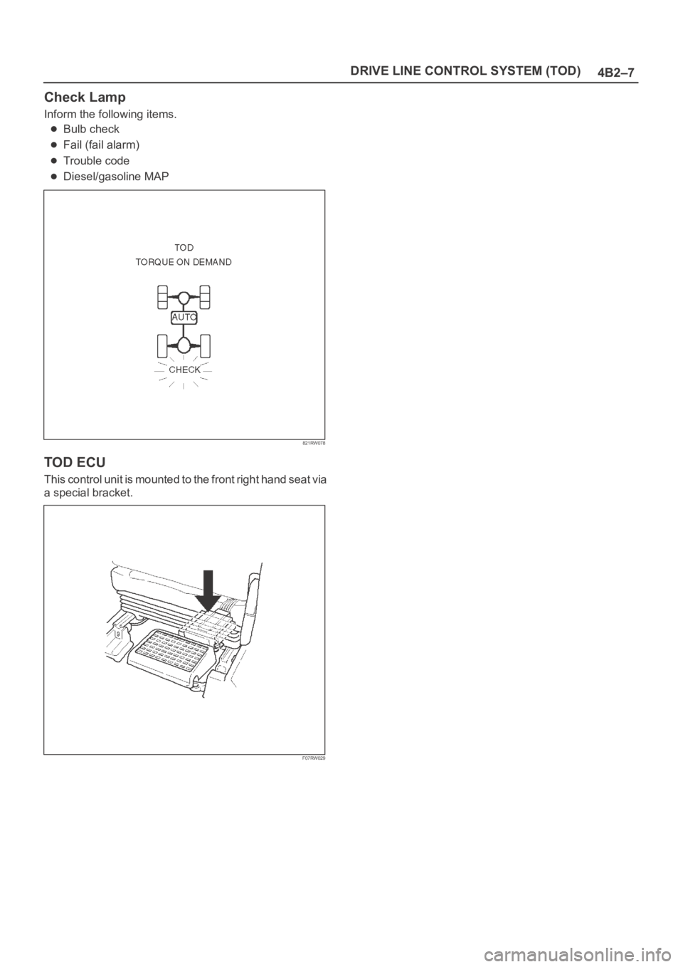
Check Lamp
Inform the following items.
Bulb check
Fail (fail alarm)
Trouble code
Diesel/gasoline MAP
821RW078
TOD ECU
This control unit is mounted to the front right hand seat via
a special bracket.
F07RW029
Page 4217 of 6000

4C–11 DRIVE SHAFT SYSTEM
Reassembly
1. Install wheel pin.
Place the hub on a wood workbench or a block of
wood approx. 6” by 6” to protect the wheel stud
ends and threads.
Insert a wheel stud using a hammer.
Be sure the wheel stud is started squarely and
seats completely.
411RS005
2. Align scribe marks(1) and attach the hub to the disc,
then tighten the bolts to the specified torque.
Torque: 103 Nꞏm (10.5 kgꞏm/76 lb ft)
411RS003
3. Use installer 5–8840–2119–0 and grip
5–8840–0007–0, then install the inner bearing by
driving it into the hub.
411RW006
4. Use installer 5–8840–2118–0 and grip
5–8840–0007–0, then install the outer bearing by
driving it into the hub.
411RW007
Page 4309 of 6000
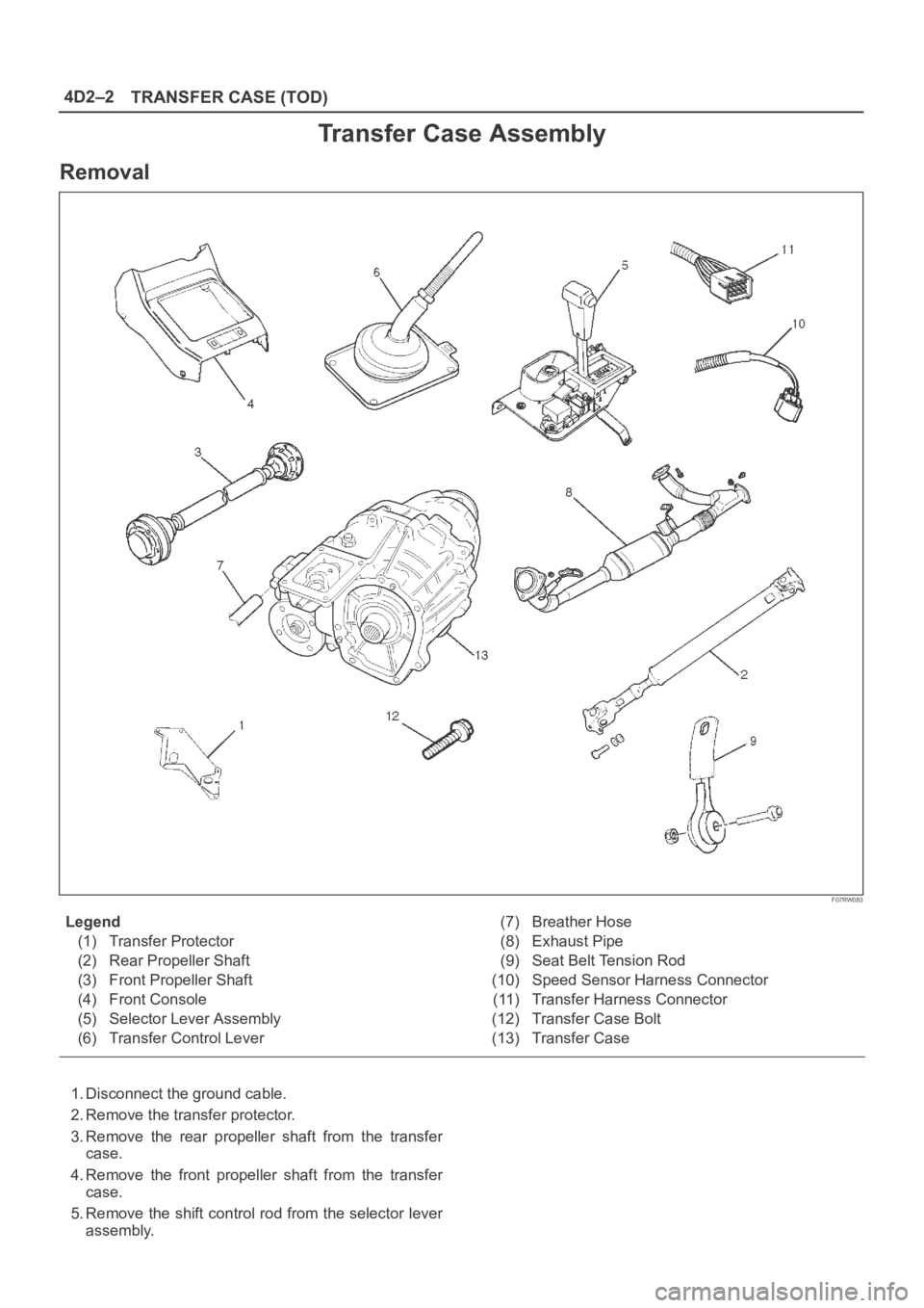
4D2–2
TRANSFER CASE (TOD)
Transfer Case Assembly
Removal
F07RW083
Legend
(1) Transfer Protector
(2) Rear Propeller Shaft
(3) Front Propeller Shaft
(4) Front Console
(5) Selector Lever Assembly
(6) Transfer Control Lever(7) Breather Hose
(8) Exhaust Pipe
(9) Seat Belt Tension Rod
(10) Speed Sensor Harness Connector
(11) Transfer Harness Connector
(12) Transfer Case Bolt
(13) Transfer Case
1. Disconnect the ground cable.
2. Remove the transfer protector.
3. Remove the rear propeller shaft from the transfer
case.
4. Remove the front propeller shaft from the transfer
case.
5. Remove the shift control rod from the selector lever
assembly.