wiring OPEL FRONTERA 1998 Workshop Manual
[x] Cancel search | Manufacturer: OPEL, Model Year: 1998, Model line: FRONTERA, Model: OPEL FRONTERA 1998Pages: 6000, PDF Size: 97 MB
Page 2118 of 6000
6E–225 4JX1–TC ENGINE DRIVEABILITY AND EMISSIONS
General Description
(ECM and Sensors)
57X Reference ECM Input
The engine control module (ECM) uses this signal from
the crankshaft position (CKP) sensor to calculate engine
RPM and crankshaft position at all engine speeds. The
ECM also uses the pulses on this circuit to initiate injector
pulses. If the ECM receives no pulses on this circuit, DTC
P0337 will set. The engine will not start and run without
using the 57X reference signal.
A/C Request Signal
This signal tells the ECM when the A/C mode is selected
at the A/C control head.
Refer to
A/C Clutch Circuit Diagnosis for A/C wiring
diagrams and diagnosis for the A/C electrical system.
Crankshaft Position (CKP) Sensor
The crankshaft position (CKP) sensor provides a signal
used by the engine control module (ECM) to calculate the
ignition sequence. The CKP sensor initiates the 57X
reference pulses which the ECM uses to calculate RPM
and crankshaft position.
Refer to
Electronic Ignition System for additional
information.
Camshaft Position (CMP) Sensor and
Signal
The camshaft position (CMP) sensor sends a CMP signal
to the ECM. The ECM uses this signal as a “cylinder
distinction” to trigger the injectors in the power order. If the
ECM detects an incorrect CMP signal while the engine is
running, DTC P0341 will set, and the ECM triggers the
injectors in the power order.
Refer to
DTC P0341.
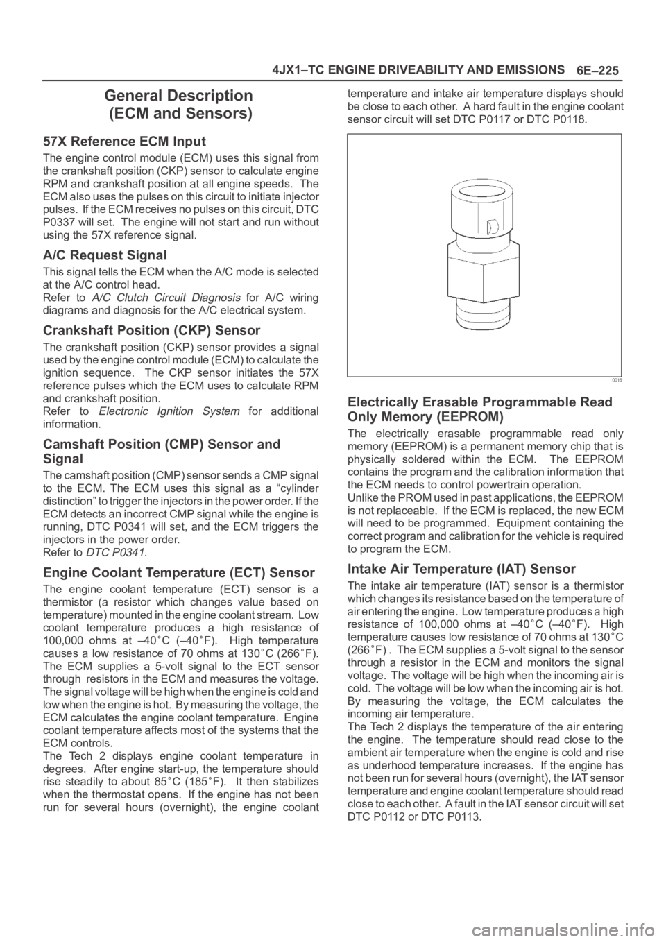
Engine Coolant Temperature (ECT) Sensor
The engine coolant temperature (ECT) sensor is a
thermistor (a resistor which changes value based on
temperature) mounted in the engine coolant stream. Low
coolant temperature produces a high resistance of
100,000 ohms at –40
C (–40F). High temperature
causes a low resistance of 70 ohms at 130
C (266F).
The ECM supplies a 5-volt signal to the ECT sensor
through resistors in the ECM and measures the voltage.
The signal voltage will be high when the engine is cold and
low when the engine is hot. By measuring the voltage, the
ECM calculates the engine coolant temperature. Engine
coolant temperature affects most of the systems that the
ECM controls.
The Tech 2 displays engine coolant temperature in
degrees. After engine start-up, the temperature should
rise steadily to about 85
C (185F). It then stabilizes
when the thermostat opens. If the engine has not been
run for several hours (overnight), the engine coolanttemperature and intake air temperature displays should
be close to each other. A hard fault in the engine coolant
sensor circuit will set DTC P0117 or DTC P0118.
0016
Electrically Erasable Programmable Read
Only Memory (EEPROM)
The electrically erasable programmable read only
memory (EEPROM) is a permanent memory chip that is
physically soldered within the ECM. The EEPROM
contains the program and the calibration information that
the ECM needs to control powertrain operation.
Unlike the PROM used in past applications, the EEPROM
is not replaceable. If the ECM is replaced, the new ECM
will need to be programmed. Equipment containing the
correct program and calibration for the vehicle is required
to program the ECM.
Intake Air Temperature (IAT) Sensor
The intake air temperature (IAT) sensor is a thermistor
which changes its resistance based on the temperature of
air entering the engine. Low temperature produces a high
resistance of 100,000 ohms at –40
C (–40F). High
temperature causes low resistance of 70 ohms at 130
C
(266
F) . The ECM supplies a 5-volt signal to the sensor
through a resistor in the ECM and monitors the signal
voltage. The voltage will be high when the incoming air is
cold. The voltage will be low when the incoming air is hot.
By measuring the voltage, the ECM calculates the
incoming air temperature.
The Tech 2 displays the temperature of the air entering
the engine. The temperature should read close to the
ambient air temperature when the engine is cold and rise
as underhood temperature increases. If the engine has
not been run for several hours (overnight), the IAT sensor
temperature and engine coolant temperature should read
close to each other. A fault in the IAT sensor circuit will set
DTC P0112 or DTC P0113.
Page 2121 of 6000
6E–228
4JX1–TC ENGINE DRIVEABILITY AND EMISSIONS
General Description (Air Induction)
Air Induction System
The air induction system filters contaminants from the
outside air, and directs the progress of the air as it is
drawn into the engine. A remote-mounted air cleaner
prevents dirt and debris in the air from entering the
engine. The air duct assembly routes filtered air to the
throttle body. Air enters the engine by to following steps:
1. Through the throttle body.
2. Into the intake manifold.
3. Through the cylinder head intake ports.
4. Into the cylinders.
General Description (Fuel Metering)
Deceleration Mode
The ECM reduces the amount of fuel injected when it
detects a decrease in the Accelerator position.
Fuel Injector
Fuel injector comprises the solenoid, hydraulic line, and
fuel line. Fuel injection is controlled by the continuity time
signal and continuity start timing signal from ECM to the
solenoid
ECM determines the running conditions of engine by
input signals such as engine speed. Accelerator throttle
valve opening, and engine coolant temperature, thereby
to send the solenoid the best suited signal to the engine
status. When current is carried to the solenoid, the
armature opens the poppet valve to alow high pressure oil
to run into the injector. Under the pressure of the oil, the
piston and plunger are depressed to compress the fuel in
the combustion chamber of the plunger. Specifically, the
pressure of the fuel compressed is increased by a piston
top/ plunger bottom area ratio over the pressure of high
pressure oil, thereby lifting the fuel nozzle end needle for
injecting fuel.
Fuel Metering System Components
The fuel metering system is made up of the following
parts:
The fuel injectors.
The intake throttle body.
The Accelerator position (AP) sensor
The ECM.
The crankshaft position (CKP) sensor.
The camshaft position (CMP) sensor.
Basic System Operation
Fuel is supplied through fuel filter to the fuel pump.
The fuel pump is installed to the oil pump, and fuel is
forced, through the fuel pump outlet, pipe and cylinder
head inside, into the fuel injector.
An orifice is provided at the rear fuel outlet of cylinder
head to control the pressure of oil.The injector is controlled by ECM which gives
opening/closing commands to the solenoid installed on
the top of the injector. Opening/closing operation of the
pressurized engine oil circuit of the injector controls fuel
injection quantity, fuel injection timing, etc.
A/C Clutch Diagnosis
A/C Request Signal
This signal tells the ECM when the A/C mode is selected
at the A/C control head. The ECM uses this to adjust the
idle speed.
Refer to
A/C Clutch Circuit Diagnosis for A/C wiring
diagrams and diagnosis for A/C electrical system.
General Description Exhaust Gas
Recirculation (EGR) System
EGR Purpose
The exhaust gas recirculation (EGR) system is use to
reduce emission levels of oxides of nitrogen (NOx). NOx
emission levels are caused by a high combustion
temperature. The EGR system lowers the NOx emission
levels by decreasing the combustion temperature.
The ECM uses information from the following sensors to
control EGR valve boost pressure.
ECT
ITP
Engine Speed
AP sensor
Page 2157 of 6000

7A–3 AUTOMATIC TRANSMISSION (4L30–E)
Service Precaution
WARNING: IF SO EQUIPPED WITH A
SUPPLEMENTAL RESTRAINT SYSTEM (SRS),
REFER TO THE SRS COMPONENT AND WIRING
LOCATION VIEW IN ORDER TO DETERMINE
WHETHER YOU ARE PERFORMING SERVICE ON OR
NEAR THE SRS COMPONENTS OR THE SRS
WIRING. WHEN YOU ARE PERFORMING SERVICE
ON OR NEAR THE SRS COMPONENTS OR THE SRS
WIRING, REFER TO THE SRS SERVICE
INFORMATION. FAILURE TO FOLLOW WARNINGS
COULD RESULT IN POSSIBLE AIR BAG
DEPLOYMENT, PERSONAL INJURY, OR
OTHERWISE UNNEEDED SRS SYSTEM REPAIRS.CAUTION: Always use the correct fastener in the
proper location. When you replace a fastener, use
ONLY the exact part number for that application.
ISUZU will call out those fasteners that require a
replacement after removal. ISUZU will also call out
the fasteners that require thread lockers or thread
sealant. UNLESS OTHERWISE SPECIFIED, do not
use supplemental coatings (Paints, greases, or other
corrosion inhibitors) on threaded fasteners or
fastener joint interfaces. Generally, such coatings
adversely affect the fastener torque and the joint
clamping force, and may damage the fastener. When
you install fasteners, use the correct tightening
sequence and specifications. Following these
instructions can help you avoid damage to parts and
systems.
Construction
A07RS001
Legend
(1) Torque Converter Clutch (TCC)
(2) Fourth Clutch (C4)
(3) Overrun Clutch (OC)
(4) Overdrive Unit
(5) Reverse Clutch (RC)
(6) Second Clutch (C2)(7) Third Clutch (C3)
(8) Ravigneaux Planetary Gear Set
(9) Brake Band (B)
(10) Overdrive Free Wheel (One Way Clutch)
(OFW)
(11) Sprag Free Wheel (One Way Clutch) (PFW)
Page 2172 of 6000
7A–18
AUTOMATIC TRANSMISSION (4L30–E)
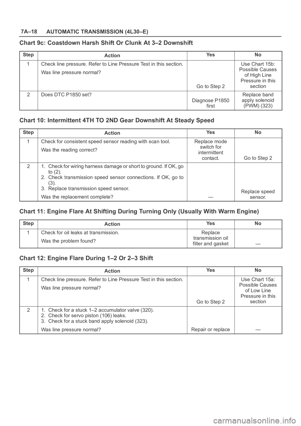
Chart 9c: Coastdown Harsh Shift Or Clunk At 3–2 Downshift
StepActionYe sNo
1Check line pressure. Refer to Line Pressure Test in this section.
Was line pressure normal?
Go to Step 2
Use Chart 15b:
Possible Causes
of High Line
Pressure in this
section
2Does DTC P1850 set?
Diagnose P1850
first
Replace band
apply solenoid
(PWM) (323)
Chart 10: Intermittent 4TH TO 2ND Gear Downshift At Steady Speed
StepActionYe sNo
1Check for consistent speed sensor reading with scan tool.
Was the reading correct?Replace mode
switch for
intermittent
contact.
Go to Step 2
21. Check for wiring harness damage or short to ground. If OK, go
to (2).
2. Check transmission speed sensor connections. If OK, go to
(3).
3. Replace transmission speed sensor.
Was the replacement complete?
—
Replace speed
sensor.
Chart 11: Engine Flare At Shifting During Turning Only (Usually With Warm Engine)
StepActionYe sNo
1Check for oil leaks at transmission.
Was the problem found?Replace
transmission oil
filter and gasket
—
Chart 12: Engine Flare During 1–2 Or 2–3 Shift
StepActionYe sNo
1Check line pressure. Refer to Line Pressure Test in this section.
Was line pressure normal?
Go to Step 2
Use Chart 15a:
Possible Causes
of Low Line
Pressure in this
section
21. Check for a stuck 1–2 accumulator valve (320).
2. Check for servo piston (106) leaks.
3. Check for a stuck band apply solenoid (323).
Was line pressure normal?
Repair or replace—
Page 2182 of 6000
7A–28
AUTOMATIC TRANSMISSION (4L30–E)
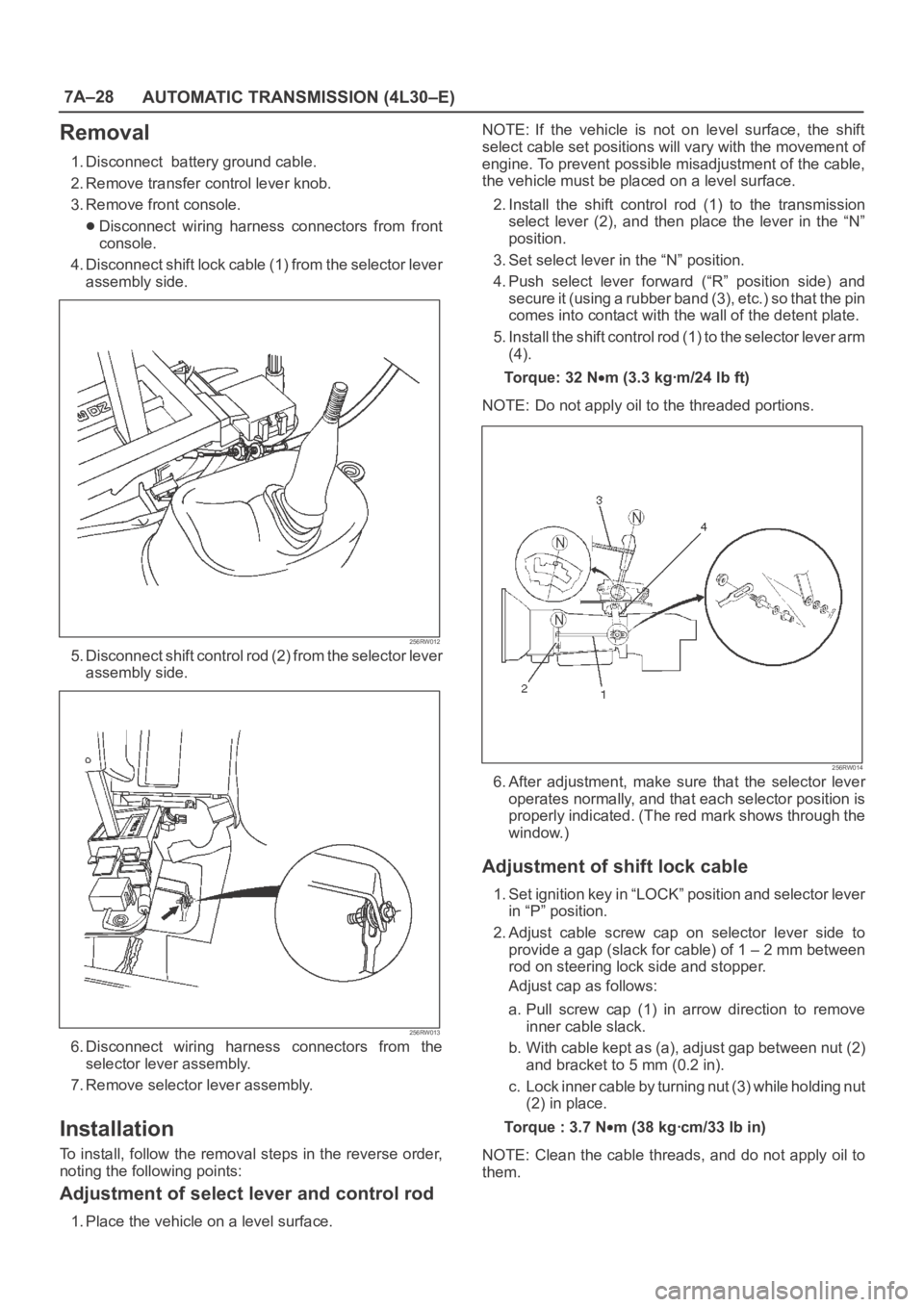
Removal
1. Disconnect battery ground cable.
2. Remove transfer control lever knob.
3. Remove front console.
Disconnect wiring harness connectors from front
console.
4. Disconnect shift lock cable (1) from the selector lever
assembly side.
256RW012
5. Disconnect shift control rod (2) from the selector lever
assembly side.
256RW013
6. Disconnect wiring harness connectors from the
selector lever assembly.
7. Remove selector lever assembly.
Installation
To install, follow the removal steps in the reverse order,
noting the following points:
Adjustment of select lever and control rod
1. Place the vehicle on a level surface.NOTE: If the vehicle is not on level surface, the shift
select cable set positions will vary with the movement of
engine. To prevent possible misadjustment of the cable,
the vehicle must be placed on a level surface.
2. Install the shift control rod (1) to the transmission
select lever (2), and then place the lever in the “N”
position.
3. Set select lever in the “N” position.
4. Push select lever forward (“R” position side) and
s e c u r e i t ( u s i n g a r u b b e r b a n d ( 3 ) , e t c . ) s o t h a t t h e p i n
comes into contact with the wall of the detent plate.
5. Install the shift control rod (1) to the selector lever arm
(4).
To r q u e : 3 2 N
m (3.3 kgꞏm/24 lb ft)
NOTE: Do not apply oil to the threaded portions.
256RW014
6. After adjustment, make sure that the selector lever
operates normally, and that each selector position is
properly indicated. (The red mark shows through the
window.)
Adjustment of shift lock cable
1. Set ignition key in “LOCK” position and selector lever
in “P” position.
2. Adjust cable screw cap on selector lever side to
provide a gap (slack for cable) of 1 – 2 mm between
rod on steering lock side and stopper.
Adjust cap as follows:
a. Pull screw cap (1) in arrow direction to remove
inner cable slack.
b. With cable kept as (a), adjust gap between nut (2)
and bracket to 5 mm (0.2 in).
c. Lock inner cable by turning nut (3) while holding nut
(2) in place.
Torque : 3.7 N
m (38 kgꞏcm/33 lb in)
NOTE: Clean the cable threads, and do not apply oil to
them.
Page 2183 of 6000
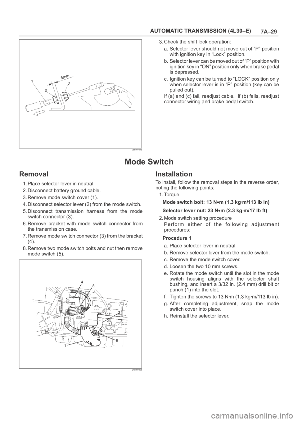
7A–29 AUTOMATIC TRANSMISSION (4L30–E)
256RW015
3. Check the shift lock operation:
a. Selector lever should not move out of “P” position
with ignition key in “Lock” position.
b. Selector lever can be moved out of “P” position with
ignition key in “ON” position only when brake pedal
is depressed.
c. Ignition key can be turned to “LOCK” position only
when selector lever is in “P” position (key can be
pulled out).
If (a) and (c) fail, readjust cable. If (b) fails, readjust
connector wiring and brake pedal switch.
Mode Switch
Removal
1. Place selector lever in neutral.
2. Disconnect battery ground cable.
3. Remove mode switch cover (1).
4. Disconnect selector lever (2) from the mode switch.
5. Disconnect transmission harness from the mode
switch connector (3).
6. Remove bracket with mode switch connector from
the transmission case.
7. Remove mode switch connector (3) from the bracket
(4).
8. Remove two mode switch bolts and nut then remove
mode switch (5).
210RW008
Installation
To install, follow the removal steps in the reverse order,
noting the following points;
1. Torque
Mode switch bolt: 13 N
m(1.3kgꞏm/113lbin)
Selector lever nut: 23 N
m (2.3 kgꞏm/17 lb ft)
2. Mode switch setting procedure
Perform either of the following adjustment
procedures:
Procedure 1
a. Place selector lever in neutral.
b. Remove selector lever from the mode switch.
c. Remove the mode switch cover.
d. Loosen the two 10 mm screws.
e. Rotate the mode switch until the slot in the mode
switch housing aligns with the selector shaft
bushing, and insert a 3/32 in. (2.4 mm) drill bit or
punch (1) into the slot.
f. Tighten the screws to 13 Nꞏm (1.3 kgꞏm/113 lb in).
g. After completing adjustment, snap the mode
switch cover into place.
h. Reinstall the selector lever.
Page 2185 of 6000

7A–31 AUTOMATIC TRANSMISSION (4L30–E)
Transmission (With Transfer Case)
Transmission And Associated Parts
240RW027
Legend
(1) Transfer Control Lever Knob
(2) Front Console
(3) Selector Lever Assembly
(4) Transfer Control Lever
(5) Transfer and Exhaust Protector
(6) Rear Propeller Shaft
(7) Front Propeller Shaft
(8) Harness Protector
(9) Rear Mount Nut(10) Third Crossmember
(11) Exhaust Pipe
(12) Transmission Oil Cooler Pipe
(13) Starter
(14) Transmission Harness Connector
(15) Under Cover
(16) Torque Converter Bolt
(17) Engine Transmission Bolt
(18) Transmission Assembly
Removal
NOTE: Before remove transmission and transfer
assembly from vehicle, change the tansfer mode to 2WD
using push button on dash panel.1. Remove engine hood.
2. Disconnect battery ground cable.
3. Remove transfer control lever knob (1) and
disconnect wiring harness connectors, then remove
front console (2).
Page 2186 of 6000

7A–32
AUTOMATIC TRANSMISSION (4L30–E)
4. Disconnect shift lock cable from the selector lever
assembly side.
256RW012
5. Disconnect wiring harness connectors.
6. Disconnect shift control rod from the selector lever
assembly side.
256RW013
7. Remove selector lever assembly (3).
8. Remove transfer control lever (4).
9. Remove transfer and exhaust protector (5).
10. Remove rear propeller shaft (6).
11. Remove front propeller shaft (7).
12. Remove harness protector (8).
13. Support transfer case with a jack and remove two rear
mount nuts (9) from the 3rd crossmember side.
14. Remove eight third crossmember bolts and third
crossmember (10).
15. Disconnect one oxygen sensor connector from the
transmission harness.
150RW002
16. Remove exhaust pipe (11).
17. Disconnect transmission oil cooler pipe (12) from A/T
side.
18. Remove oil pipe clamp from torque converter
housing bracket.
253RW001
19. Loosen oil pipe clamp bolt at the engine mount side.
20. Remove starter (13).
21. Disconnect fuel pipe clamp bracket from
transmission side.
22. Disconnect transmission harness connectors (14)
from transmission, and transfer.
23. Remove flywheel under covers (3 pieces) (15) from
transmission case.
24. Lower the front of the transmission a little, then
remove flywheel torque converter fixing bolts (6
pieces) (16) by turning crankshaft.
25. Support the transmission with a transmission jack,
and hoist engine with a chain block.
26. Remove engine transmission fixing bolts (17).
Page 2189 of 6000

7A–35 AUTOMATIC TRANSMISSION (4L30–E)
17. Install harness protector.
815RW002
18. Install the front propeller shaft, and tighten the bolts to
the specified torque.
Torque: 63 N
m (6.4 kgꞏm/46 lb ft)
19. Install the rear propeller shaft, and tighten the bolts to
the specified torque.
Torque: 63 N
m (6.4 kgꞏm/46 lb ft)
20. Install the transfer and exhaust protectors, tand
tighten the bolts to the specified torque.
Torque: 37 N
m (3.8 kgꞏm/27 lb ft)
21. Install the transfer control lever.
22. Install the selector lever assembly.
23. Connect the shift control rod to selector lever
assembly.
24. Connect the wiring harness connectors.
25. Connect the shift lock cable to selector lever
assembly. Refer to Selector Lever in this section.
26. Connect the wiring harness connectors to front
console.
27. Install the front console.
28. Install the transfer control lever knob.
29. Connect the battery ground cable.
30. Install the engine hood.
Page 2190 of 6000

7A–36
AUTOMATIC TRANSMISSION (4L30–E)
Solenoid (Main Case Valve Body)
Removal
1. Raise the vehicle and support it on jack stands.
2. Disconnect battery ground cable.
3. Remove transfer and exhaust protectors.
4. Drain fluid.
5. Remove exhaust pipe and disconnect oxygen sensor
connector.
6. Support transfer case with a jack and remove third
crossmember.
7. Remove sixteen 10 mm screws, main case oil pan,
magnet, and gasket.
8. Remove three 13 mm screws, oil filter.
9. Disconnect wiring harness from band control
solenoid and shift solenoids. Pull only on connectors,
not on wiring harness.
10. Remove spring pin for shift solenoid A, shift solenoid
B, and band control solenoid respectively, using
suitable pliers taking care not to damage solenoids.
210RW010
244RW003
11. Remove shift solenoid A, shift solenoid B, band
control solenoid, and gaskets from main case valve
body. Do not pull on wiring harness. Remove
solenoids by grasping the metal tip.
Installation
1. Install shift solenoid A, shift solenoid B, band control
solenoid with new gaskets to main case valve body
respectively.
2. Carefully install spring pin with hammer to avoid
damage to valve body, etc.
243RW004
3. Connect wiring harness to solenoids.
4. Install oil filter with a new gasket and the three 13 mm
screws. Tighten the screws to the specified torque.
To r q u e : 2 0 N
m (2.0 kgꞏm/15 lb ft)
5. Install magnet, main case oil pan with new gasket,
sixteen 10 mm screws. Tighten the screws to the
specified torque.
To r q u e : 11 N
m (1.1 kgꞏm/96 lb in)
6. Install third crossmember and rear mount nuts.
Tighten the nuts and bolts to the specified torque.
Third crossmember bolt: 50 N
m
(5.1 kgꞏm/37 lb ft)
Rear mount nut: 50 N
m (5.1 kgꞏm/37 lb ft)
7. Install exhaust pipe and connect oxygen sensor
connector. Tighten the bolts to the specified torque.
Exhaust pipe flange bolt torque:
43 N
m(4.4kgꞏm/32lbft)
8. Install the transfer and exhaust protectors. Tighten
the bolts to the specified torque.
Torque: 37 N
m (3.8 kgꞏm/27 lb ft)
9. Fill transmission through the overfill screw hole of oil
pan, using ATF DEXRON
–III. Refer to Changing
Transmission Fluid in this section.
10. Connect the battery ground cable.