clock setting OPEL FRONTERA 1998 Workshop Manual
[x] Cancel search | Manufacturer: OPEL, Model Year: 1998, Model line: FRONTERA, Model: OPEL FRONTERA 1998Pages: 6000, PDF Size: 97 MB
Page 450 of 6000
4A1–13 DIFFERENTIAL (FRONT)
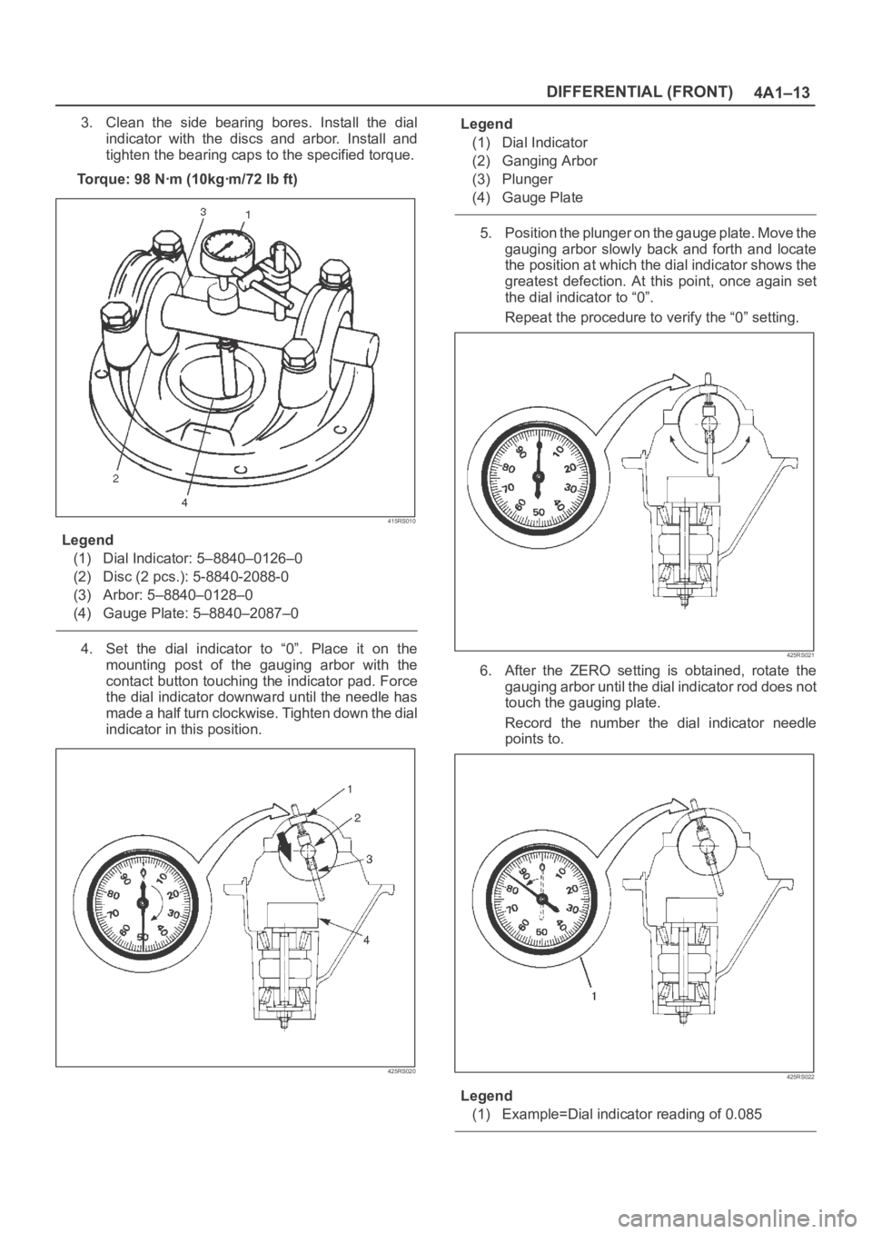
3. Clean the side bearing bores. Install the dial
indicator with the discs and arbor. Install and
tighten the bearing caps to the specified torque.
To r q u e : 9 8 N ꞏm ( 1 0 k g ꞏm / 7 2 l b f t )
415RS010
Legend
(1) Dial Indicator: 5–8840–0126–0
(2) Disc (2 pcs.): 5-8840-2088-0
(3) Arbor: 5–8840–0128–0
(4) Gauge Plate: 5–8840–2087–0
4. Set the dial indicator to “0”. Place it on the
mounting post of the gauging arbor with the
contact button touching the indicator pad. Force
the dial indicator downward until the needle has
made a half turn clockwise. Tighten down the dial
indicator in this position.
425RS020
Legend
(1) Dial Indicator
(2) Ganging Arbor
(3) Plunger
(4) Gauge Plate
5. Position the plunger on the gauge plate. Move the
gauging arbor slowly back and forth and locate
the position at which the dial indicator shows the
greatest defection. At this point, once again set
the dial indicator to “0”.
Repeat the procedure to verify the “0” setting.
425RS021
6. After the ZERO setting is obtained, rotate the
gauging arbor until the dial indicator rod does not
touch the gauging plate.
Record the number the dial indicator needle
points to.
425RS022
Legend
(1) Example=Dial indicator reading of 0.085
Page 481 of 6000
4A2A–14
DIFFERENTIAL (REAR 220mm)
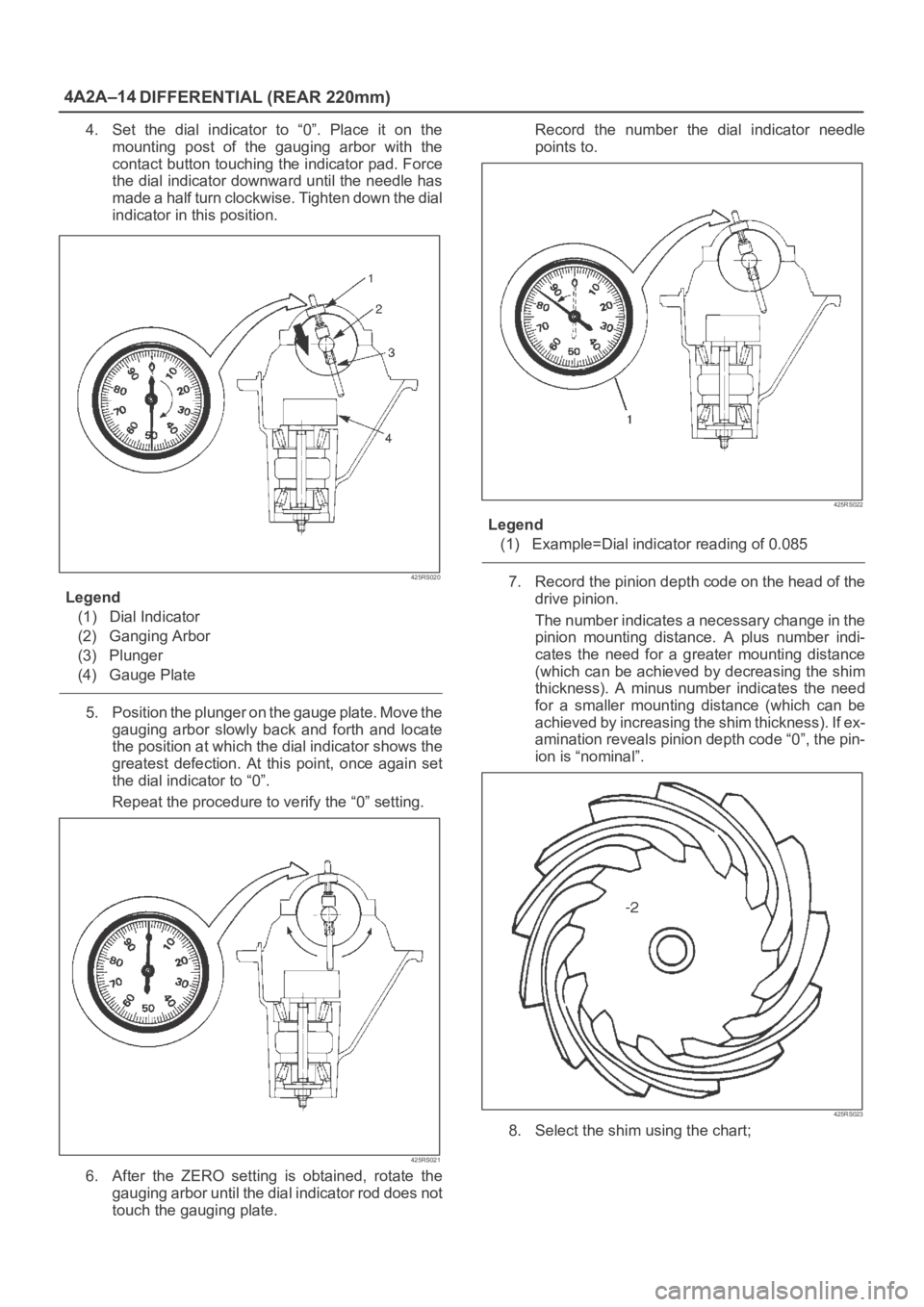
4. Set the dial indicator to “0”. Place it on the
mounting post of the gauging arbor with the
contact button touching the indicator pad. Force
the dial indicator downward until the needle has
made a half turn clockwise. Tighten down the dial
indicator in this position.
425RS020
Legend
(1) Dial Indicator
(2) Ganging Arbor
(3) Plunger
(4) Gauge Plate
5. Position the plunger on the gauge plate. Move the
gauging arbor slowly back and forth and locate
the position at which the dial indicator shows the
greatest defection. At this point, once again set
the dial indicator to “0”.
Repeat the procedure to verify the “0” setting.
425RS021
6. After the ZERO setting is obtained, rotate the
gauging arbor until the dial indicator rod does not
touch the gauging plate.Record the number the dial indicator needle
points to.
425RS022
Legend
(1) Example=Dial indicator reading of 0.085
7. Record the pinion depth code on the head of the
drive pinion.
The number indicates a necessary change in the
pinion mounting distance. A plus number indi-
cates the need for a greater mounting distance
(which can be achieved by decreasing the shim
thickness). A minus number indicates the need
for a smaller mounting distance (which can be
achieved by increasing the shim thickness). If ex-
amination reveals pinion depth code “0”, the pin-
ion is “nominal”.
425RS023
8. Select the shim using the chart;
Page 517 of 6000
4A2B–14DIFFERENTIAL (REAR 244mm)
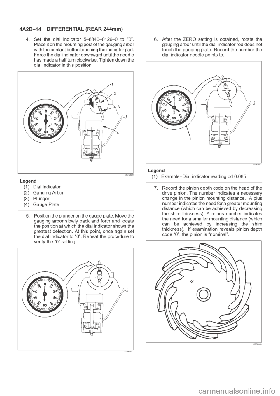
4. Set the dial indicator 5–8840–0126–0 to “0”.
Place it on the mounting post of the gauging arbor
with the contact button touching the indicator pad.
Force the dial indicator downward until the needle
has made a half turn clockwise. Tighten down the
dial indicator in this position.
425RS020
Legend
(1) Dial Indicator
(2) Ganging Arbor
(3) Plunger
(4) Gauge Plate
5. Position the plunger on the gauge plate. Move the
gauging arbor slowly back and forth and locate
the position at which the dial indicator shows the
greatest defection. At this point, once again set
the dial indicator to “0”. Repeat the procedure to
verify the “0” setting.
425RS021
6. After the ZERO setting is obtained, rotate the
gauging arbor until the dial indicator rod does not
touch the gauging plate. Record the number the
dial indicator needle points to.
425RS022
Legend
(1) Example=Dial indicator reading od 0.085
7. Record the pinion depth code on the head of the
drive pinion. The number indicates a necessary
change in the pinion mounting distance. A plus
number indicates the need for a greater mounting
distance (which can be achieved by decreasing
the shim thickness). A minus number indicates
the need for a smaller mounting distance (which
can be achieved by increasing the shim
thickness). If examination reveals pinion depth
code “0”, the pinion is “nominal”.
425RS023
Page 1375 of 6000

6E–258
ENGINE DRIVEABILITY AND EMISSIONS
Diagnostic Trouble Code (DTC) P1625 PCM Unexpected Reset
Circuit Description
The powertrain control module (PCM) monitors
unexpected PCM reset. This will not turn on MIL light on,
only records code DTC P1625.
Conditions for Setting the DTC
Clock or COP reset.
Action Taken When the DTC Sets
The PCM will not illuminate the malfunction indicator
lamp (MIL).
The PCM will store conditions which were present
when the DTC was set as Failure Records only. This
information will not be stored as Freeze Frame data.
Conditions for Clearing the MIL/DTC
DTC P1625 can be cleared by using the Tech 2 “Clear
Info” function or by disconnecting the PCM battery
feed.
Diagnostic Aids
Check for the following conditions:
P1625 alone stored does not need diagnosis. Clear
DTC code.
Page 3478 of 6000
SUPPLEMENTAL RESTRAINT SYSTEM9J–41
Installation
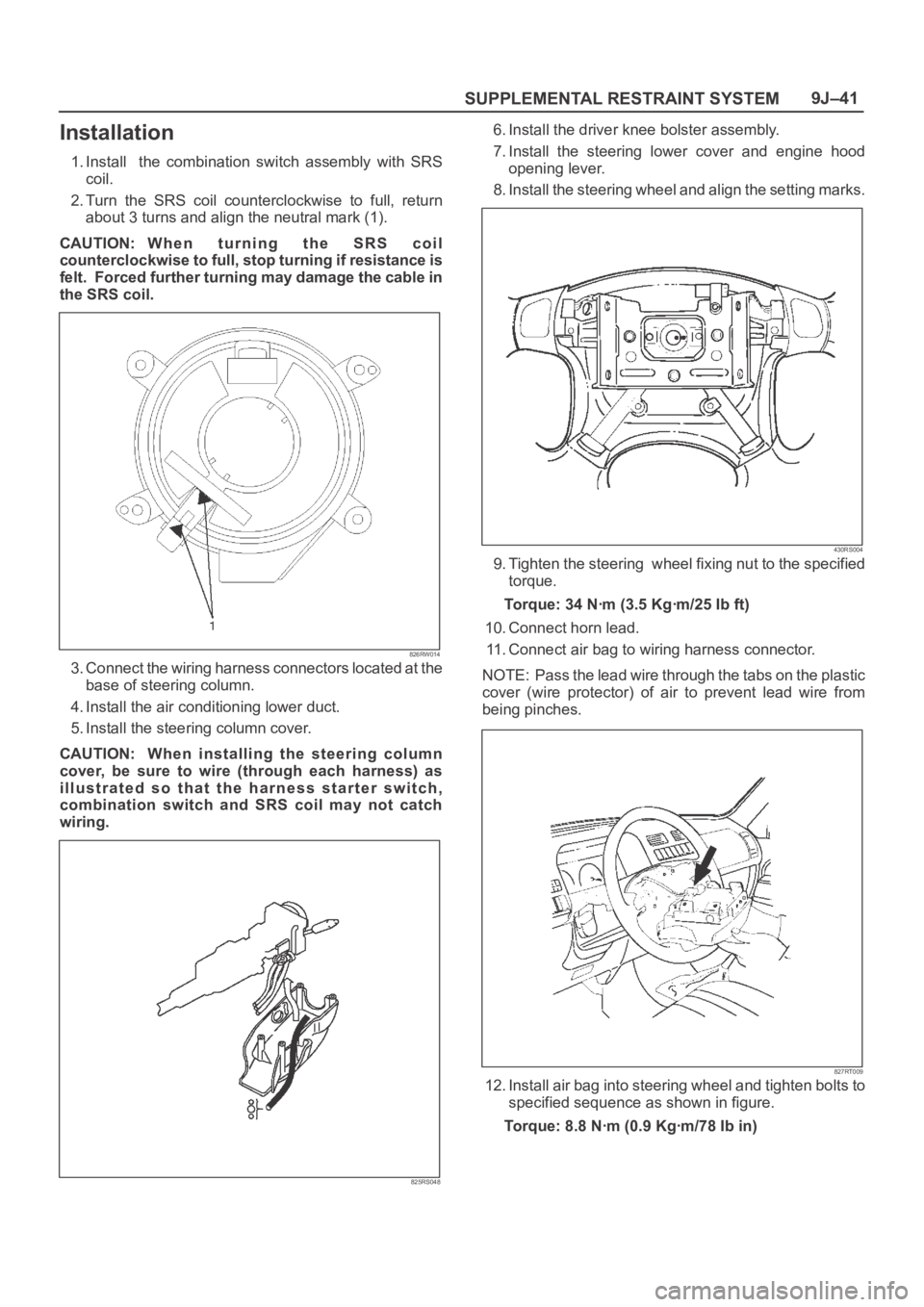
1. Install the combination switch assembly with SRS
coil.
2. Turn the SRS coil counterclockwise to full, return
about 3 turns and align the neutral mark (1).
CAUTION: W h e n t u r n i n g t h e S R S c o i l
counterclockwise to full, stop turning if resistance is
felt. Forced further turning may damage the cable in
the SRS coil.
826RW014
3. Connect the wiring harness connectors located at the
base of steering column.
4. Install the air conditioning lower duct.
5. Install the steering column cover.
CAUTION: When installing the steering column
cover, be sure to wire (through each harness) as
illustrated so that the harness starter switch,
combination switch and SRS coil may not catch
wiring.
825RS048
6. Install the driver knee bolster assembly.
7. Install the steering lower cover and engine hood
opening lever.
8. Install the steering wheel and align the setting marks.
430RS004
9. Tighten the steering wheel fixing nut to the specified
torque.
Torque: 34 Nꞏm (3.5 Kgꞏm/25 Ib ft)
10. Connect horn lead.
11. Connect air bag to wiring harness connector.
NOTE: Pass the lead wire through the tabs on the plastic
cover (wire protector) of air to prevent lead wire from
being pinches.
827RT009
12. Install air bag into steering wheel and tighten bolts to
specified sequence as shown in figure.
Torque: 8.8 Nꞏm (0.9 Kgꞏm/78 Ib in)
Page 3483 of 6000
SUPPLEMENTAL RESTRAINT SYSTEM 9J–46
NOTE: SRS coil is a part of combination switch
assembly, which cannot be replaced separately.
Therefore, be sure not to remove the SRS coil from the
combination switch assembly.
15. Remove the snap ring.
16. Remove the cushion rubber.
17. Disconnect shift lock cable (A/T only).
18. Disconnect the starter switch harness connector
located base of steering column.
19. Remove steering lock cylinder assembly.
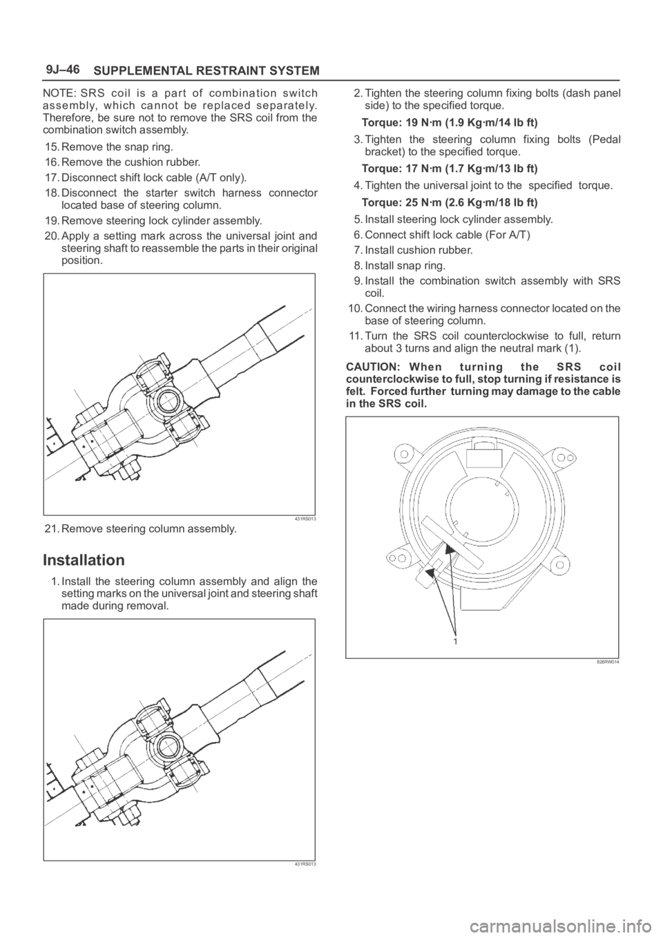
20. Apply a setting mark across the universal joint and
steering shaft to reassemble the parts in their original
position.
431RS013
21. Remove steering column assembly.
Installation
1. Install the steering column assembly and align the
setting marks on the universal joint and steering shaft
made during removal.
431RS013
2. Tighten the steering column fixing bolts (dash panel
side) to the specified torque.
Torque: 19 Nꞏm (1.9 Kgꞏm/14 Ib ft)
3. Tighten the steering column fixing bolts (Pedal
bracket) to the specified torque.
Torque: 17 Nꞏm (1.7 Kgꞏm/13 Ib ft)
4. Tighten the universal joint to the specified torque.
Torque: 25 Nꞏm (2.6 Kgꞏm/18 Ib ft)
5. Install steering lock cylinder assembly.
6. Connect shift lock cable (For A/T)
7. Install cushion rubber.
8. Install snap ring.
9. Install the combination switch assembly with SRS
coil.
10. Connect the wiring harness connector located on the
base of steering column.
11. Turn the SRS coil counterclockwise to full, return
about 3 turns and align the neutral mark (1).
CAUTION: W h e n t u r n i n g t h e S R S c o i l
counterclockwise to full, stop turning if resistance is
felt. Forced further turning may damage to the cable
in the SRS coil.
826RW014
Page 3953 of 6000

4A1–13 DIFFERENTIAL (FRONT)
3. Clean the side bearing bores. Install the dial
indicator with the discs and arbor. Install and
tighten the bearing caps to the specified torque.
To r q u e : 9 8 N ꞏm ( 1 0 k g ꞏm / 7 2 l b f t )
415RS010
Legend
(1) Dial Indicator: 5–8840–0126–0
(2) Disc (2 pcs.): 5-8840-2088-0
(3) Arbor: 5–8840–0128–0
(4) Gauge Plate: 5–8840–2087–0
4. Set the dial indicator to “0”. Place it on the
mounting post of the gauging arbor with the
contact button touching the indicator pad. Force
the dial indicator downward until the needle has
made a half turn clockwise. Tighten down the dial
indicator in this position.
425RS020
Legend
(1) Dial Indicator
(2) Gauging Arbor
(3) Plunger
(4) Gauge Plate
5. Position the plunger on the gauge plate. Move the
gauging arbor slowly back and forth and locate
the position at which the dial indicator shows the
greatest defection. At this point, once again set
the dial indicator to “0”.
Repeat the procedure to verify the “0” setting.
425RS021
6. After the ZERO setting is obtained, rotate the
gauging arbor until the dial indicator rod does not
touch the gauging plate.
Record the number the dial indicator needle
points to.
425RS022
Legend
(1) Example=Dial indicator reading of 0.085
Page 3986 of 6000

DIFFERENTIAL (REAR 220mm)
4A2A–17
4. Set the dial indicator to “0”. Place it on the
mounting post of the gauging arbor with the
contact button touching the indicator pad. Force
the dial indicator downward until the needle has
made a half turn clockwise. Tighten down the dial
indicator in this position.
425RS020
Legend
(1) Dial Indicator
(2) Ganging Arbor
(3) Plunger
(4) Gauge Plate
5. Position the plunger on the gauge plate. Move the
gauging arbor slowly back and forth and locate
the position at which the dial indicator shows the
greatest defection. At this point, once again set
the dial indicator to “0”.
Repeat the procedure to verify the “0” setting.
425RS021
6. After the ZERO setting is obtained, rotate the
gauging arbor until the dial indicator rod does not
touch the gauging plate.
Record the number the dial indicator needle
points to.
425RS022
Legend
(1) Example=Dial indicator reading of 0.085
7. Record the pinion depth code on the head of the
drive pinion.
The number indicates a necessary change in the
pinion mounting distance. A plus number indi-
cates the need for a greater mounting distance
(which can be achieved by decreasing the shim
thickness). A minus number indicates the need
for a smaller mounting distance (which can be
achieved by increasing the shim thickness). If ex-
amination reveals pinion depth code “0”, the pin-
ion is “nominal”.
425RS023
Page 4025 of 6000

4A2B–18DIFFERENTIAL (REAR 244mm)
4. Set the dial indicator 5–8840–0126–0 to “0”.
Place it on the mounting post of the gauging arbor
with the contact button touching the indicator pad.
Force the dial indicator downward until the needle
has made a half turn clockwise. Tighten down the
dial indicator in this position.
425RS020
Legend
(1) Dial Indicator
(2) Ganging Arbor
(3) Plunger
(4) Gauge Plate
5. Position the plunger on the gauge plate. Move the
gauging arbor slowly back and forth and locate
the position at which the dial indicator shows the
greatest defection. At this point, once again set
the dial indicator to “0”. Repeat the procedure to
verify the “0” setting.
425RS021
6. After the ZERO setting is obtained, rotate the
gauging arbor until the dial indicator rod does not
touch the gauging plate. Record the number the
dial indicator needle points to.
425RS022
Legend
(1) Example=Dial indicator reading od 0.085
7. Record the pinion depth code on the head of the
drive pinion. The number indicates a necessary
change in the pinion mounting distance. A plus
number indicates the need for a greater mounting
distance (which can be achieved by decreasing
the shim thickness). A minus number indicates
the need for a smaller mounting distance (which
can be achieved by increasing the shim
thickness). If examination reveals pinion depth
code “0”, the pinion is “nominal”.
425RS023
Page 4915 of 6000

6E–258
ENGINE DRIVEABILITY AND EMISSIONS
Diagnostic Trouble Code (DTC) P1625 PCM Unexpected Reset
Circuit Description
The powertrain control module (PCM) monitors
unexpected PCM reset. This will not turn on MIL light on,
only records code DTC P1625.
Conditions for Setting the DTC
Clock or COP reset.
Action Taken When the DTC Sets
The PCM will not illuminate the malfunction indicator
lamp (MIL).
The PCM will store conditions which were present
when the DTC was set as Failure Records only. This
information will not be stored as Freeze Frame data.
Conditions for Clearing the MIL/DTC
DTC P1625 can be cleared by using the Tech 2 “Clear
Info” function or by disconnecting the PCM battery
feed.
Diagnostic Aids
Check for the following conditions:
P1625 alone stored does not need diagnosis. Clear
DTC code.