belt OPEL FRONTERA 1998 Owner's Manual
[x] Cancel search | Manufacturer: OPEL, Model Year: 1998, Model line: FRONTERA, Model: OPEL FRONTERA 1998Pages: 6000, PDF Size: 97 MB
Page 991 of 6000

6A–35
ENGINE MECHANICAL
014RW024
Legend
(1) Right Bank
(2) Left Bank(3) Alignment Mark on Camshaft Drive Gear
(4) Alignment Mark on Camshaft
(5) Alignment Mark on Retainer
3. Tighten twenty bolts on numerical order an one
side bank as shown in the illustration.
Torque : 10 Nꞏm (1.0 Kgꞏm/89 lb in)
014RW031
5. Install cylinder head cover RH.
Refer to installation procedure for CYLINDER
HEAD COVER RH in this manual.
6. Install cylinder head cover LH.
Refer to installation procedure for CYLINDER
HEAD COVER LH in this manual.
7. Install timing belt.
Refer to installation procedure for TIMING BELT in
this manual.8. Install crankshaft pulley.
Refer to installation procedure for CRANKSHAFT
PULLEY in this manual.
Accelerator pedal cable adjustment
1. Loosen adjusting nut and lock nut.
2. Pull outer cable while closing fully the throttle
valve.
3. Tighten adjusting nut and lock nut temporarily.
Page 993 of 6000

6A–37
ENGINE MECHANICAL
Cylinder Head
Removal
1. Remove engine hood.
2. Disconnect battery ground cable.
3. Drain radiator coolant.
4. Drain engine oil.
5. Remove crankshaft pulley.
Refer to removal procedure for Crankshaft Pulley in
this manual.
6. Remove timing belt.
Refer to removal procedure for Timing Belt in this
manual.
7. Remove cylinder head cover LH.
Refer to removal procedure for Cylinder Head
Cover LH in this manual.
8. Remove cylinder head cover RH.
Refer to removal procedure for Cylinder Head
Cover RH in this manual.
9. Remove common chamber.
Refer to removal procedure for Common Chamber
in this manual.
10. Remove cylinder head assembly.
1. Loosen eights bolts for tight cylinder head.
2. Remove cylinder head assembly.
014RW028
Legend
(1) Cylinder Head
(2) Cylinder Head Bolt
(3) Camshaft
Installation
1. Install cylinder head assembly to cylinder block.
1. Put cylinder head gasket on the cylinder block.NOTE: There is discrimination mark “R” for right bank
and “L” for left bank on the cylinder head gasket as shown
in the illustration.
Do not reuse cylinder head gasket.
011RW005
2. Align dowel pin hole to dowel pin on the cylinder
block.
3. Tighten two bolts temporarily by hand to prevent
the cylinder head assembly from moving.
4. Using 9–8511–4209–0 cylinder head bolt wrench,
tighten bolts in numerical order as shown in the
illustration to the specified torque.
NOTE: Do not reuse cylinder head bolts.
Do not apply any lubricant to the cylinder head bolts.
To r q u e :
Temporary : 29 Nꞏm (3.0 Kgꞏm/21 lb ft)
Final : 64 Nꞏm (6.5 Kgꞏm/47 lb ft)
014RW029
Page 994 of 6000

6A–38
ENGINE MECHANICAL
2. Install common chamber.
Refer to installation procedure for Common
Chamber in this manual.
3. Install cylinder head cover RH.
Refer to installation procedure for Cylinder Head
Cover RH in this manual.
4. Install cylinder head cover LH.
Refer to installation procedure for Cylinder Head
Cover LH in this manual.
5. Install timing belt.
Refer to installation procedure for Timing Belt in this
manual.
6. Install crankshaft pulley.
Refer to installation procedure for Crankshaft
Pulley in this manual.
Accelerator pedal cable adjustment
1. Loosen adjusting nut and lock nut.
2. Pull outer cable while closing fully the throttle
valve.
3. Tighten adjusting nut and lock nut temporarily.
4. Loosen adjusting nut by three turns and tighten
lock nut.
Then, manually operating the throttle valve, make
sure that the valve lever returns up to the stopper
screw.
If it does not reach the stopper screw, repeat from
step 1.
035RW004
Legend
(1) Clearance
(2) Lock Nut
(3) Adjusting Nut
Page 998 of 6000

6A–42
ENGINE MECHANICAL
Crankshaft and Main Bearings
Removal
F06RW010
Legend
(1) Engine Assembly
(2) Crankshaft Pulley
(3) Timing Belt Cover
(4) Timing Belt
(5) Crankcase with Oil Pan
(6) Oil Pipe
(7) Oil Strainer(8) Oil Pump Assembly
(9) Cylinder Body Side Bolt
(10) Oil Gallery
(11) Flywheel
(12) Rear Oil Seal Retainer
(13) Connecting Rod Cap
(14) Crankshaft Main Bearing Cap
(15) Crankshaft and Main Bearing
1. Remove engine assembly.
Refer to removal procedure for Engine Assembly in
this manual.
2. Remove timing belt.
Refer to removal procedure for Timing Belt in this
manual.3. Remove oil pan and crankcase.
Refer to removal procedure for Oil Pan and
Crankcase in this manual.
4. Remove oil pipe with O-ring.
5. Remove oil strainer assembly with O-ring.
Page 1002 of 6000

6A–46
ENGINE MECHANICAL
Tighten fixing bolts to the specified torque.
Torque : 25 Nꞏm (2.5 Kgꞏm/18 lb ft)
013RW003
013RW002
13. Install timing belt.
Refer to installation procedure for Timing Belt in this
manual.
14. Install engine assembly.
Refer to installation procedure for Engine in this
manual.
Page 1004 of 6000

6A–48
ENGINE MECHANICAL
Engine Assembly
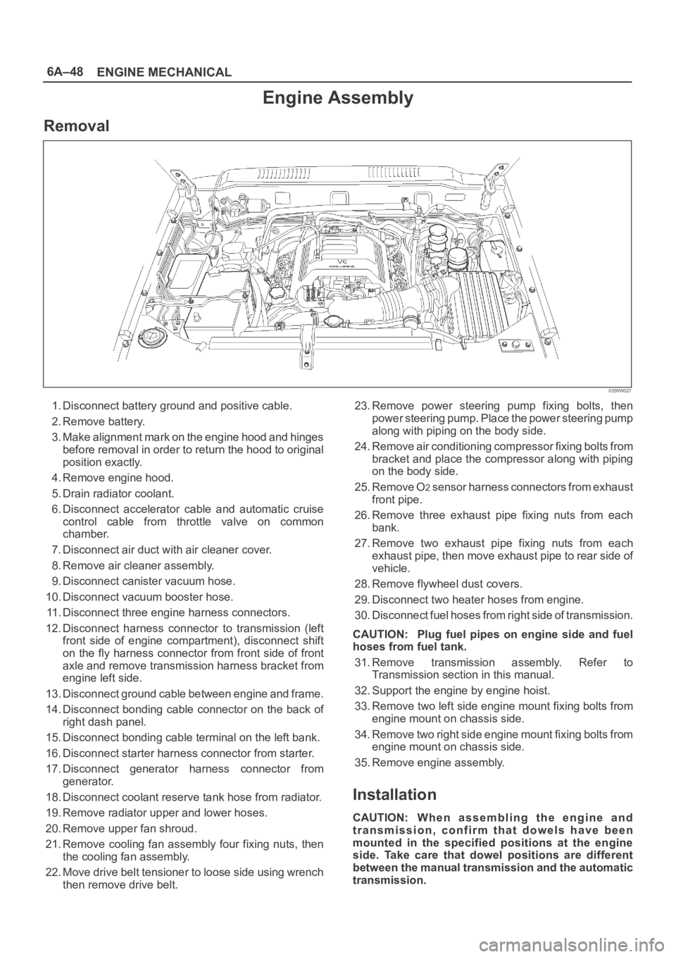
Removal
035RW027
1. Disconnect battery ground and positive cable.
2. Remove battery.
3. Make alignment mark on the engine hood and hinges
before removal in order to return the hood to original
position exactly.
4. Remove engine hood.
5. Drain radiator coolant.
6. Disconnect accelerator cable and automatic cruise
control cable from throttle valve on common
chamber.
7. Disconnect air duct with air cleaner cover.
8. Remove air cleaner assembly.
9. Disconnect canister vacuum hose.
10. Disconnect vacuum booster hose.
11. Disconnect three engine harness connectors.
12. Disconnect harness connector to transmission (left
front side of engine compartment), disconnect shift
on the fly harness connector from front side of front
axle and remove transmission harness bracket from
engine left side.
13. Disconnect ground cable between engine and frame.
14. Disconnect bonding cable connector on the back of
right dash panel.
15. Disconnect bonding cable terminal on the left bank.
16. Disconnect starter harness connector from starter.
17. Disconnect generator harness connector from
generator.
18. Disconnect coolant reserve tank hose from radiator.
19. Remove radiator upper and lower hoses.
20. Remove upper fan shroud.
21. Remove cooling fan assembly four fixing nuts, then
the cooling fan assembly.
22. Move drive belt tensioner to loose side using wrench
then remove drive belt.23. Remove power steering pump fixing bolts, then
power steering pump. Place the power steering pump
along with piping on the body side.
24. Remove air conditioning compressor fixing bolts from
bracket and place the compressor along with piping
on the body side.
25. Remove O
2 sensor harness connectors from exhaust
front pipe.
26. Remove three exhaust pipe fixing nuts from each
bank.
27. Remove two exhaust pipe fixing nuts from each
exhaust pipe, then move exhaust pipe to rear side of
vehicle.
28. Remove flywheel dust covers.
29. Disconnect two heater hoses from engine.
30. Disconnect fuel hoses from right side of transmission.
CAUTION: Plug fuel pipes on engine side and fuel
hoses from fuel tank.
31. Remove transmission assembly. Refer to
Transmission section in this manual.
32. Support the engine by engine hoist.
33. Remove two left side engine mount fixing bolts from
engine mount on chassis side.
34. Remove two right side engine mount fixing bolts from
engine mount on chassis side.
35. Remove engine assembly.
Installation
CAUTION: W h e n a s s e m b l i n g t h e e n g i n e a n d
transmission, confirm that dowels have been
mounted in the specified positions at the engine
side. Take care that dowel positions are different
between the manual transmission and the automatic
transmission.
Page 1006 of 6000

6A–50
ENGINE MECHANICAL
9. Install air conditioner compressor to engine and
tighten to the specified torque.
Torque :
M8 bolts : 22 Nꞏm (2.2 Kgꞏm/16 lb ft)
M10 bolts : 43 Nꞏm (4.4 Kgꞏm/32 lb ft)
10. Install power steering pump, tighten fixing bolt to the
specified torque.
Torque :
M8 bolts : 22Nꞏm (2.2 Kgꞏm/16 lb ft)
M10 bolts : 46 Nꞏm (4.7 Kgꞏm/34 lb ft)
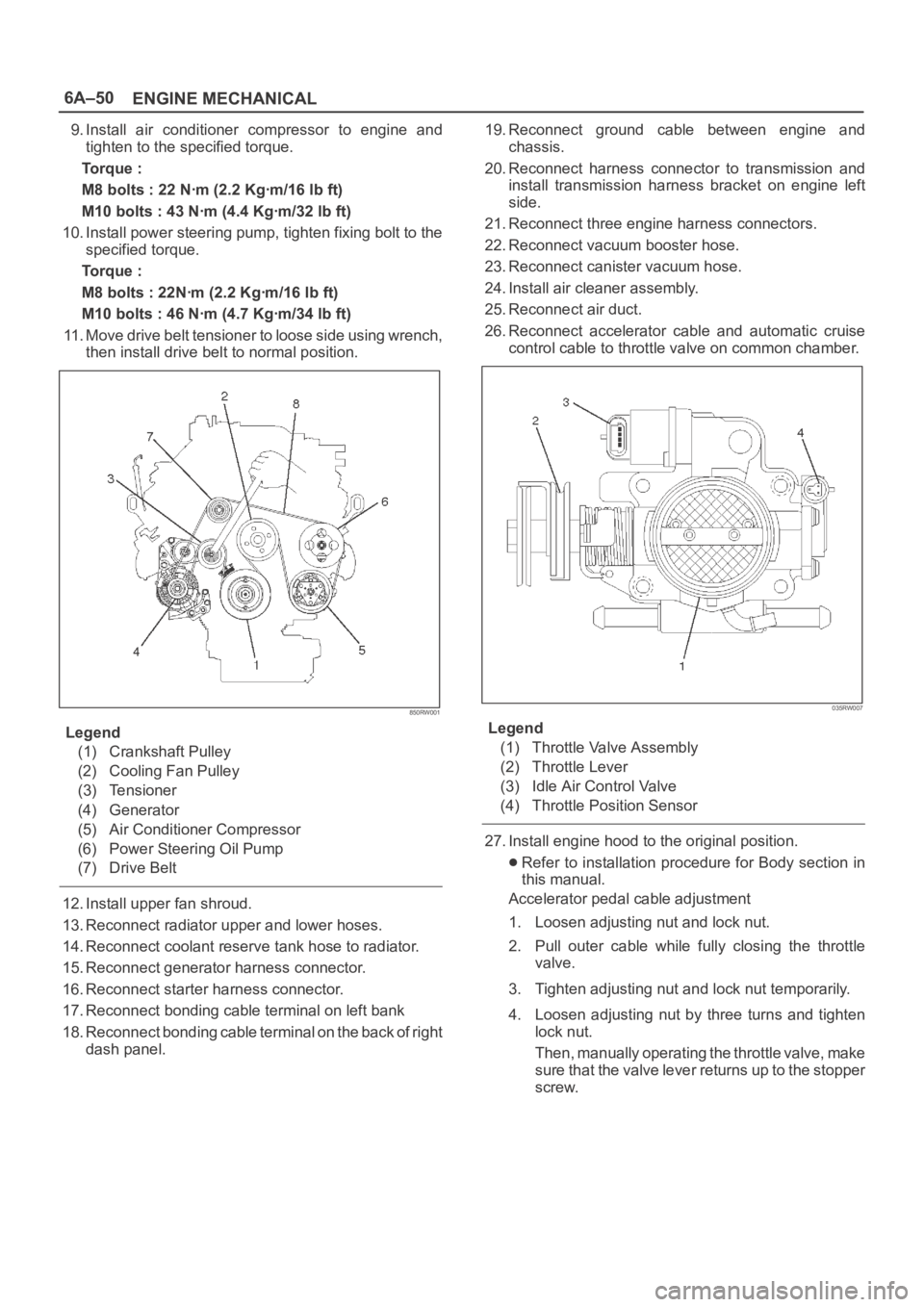
11. Move drive belt tensioner to loose side using wrench,
then install drive belt to normal position.
850RW001
Legend
(1) Crankshaft Pulley
(2) Cooling Fan Pulley
(3) Tensioner
(4) Generator
(5) Air Conditioner Compressor
(6) Power Steering Oil Pump
(7) Drive Belt
12. Install upper fan shroud.
13. Reconnect radiator upper and lower hoses.
14. Reconnect coolant reserve tank hose to radiator.
15. Reconnect generator harness connector.
16. Reconnect starter harness connector.
17. Reconnect bonding cable terminal on left bank
18. Reconnect bonding cable terminal on the back of right
dash panel.19. Reconnect ground cable between engine and
chassis.
20. Reconnect harness connector to transmission and
install transmission harness bracket on engine left
side.
21. Reconnect three engine harness connectors.
22. Reconnect vacuum booster hose.
23. Reconnect canister vacuum hose.
24. Install air cleaner assembly.
25. Reconnect air duct.
26. Reconnect accelerator cable and automatic cruise
control cable to throttle valve on common chamber.
035RW007
Legend
(1) Throttle Valve Assembly
(2) Throttle Lever
(3) Idle Air Control Valve
(4) Throttle Position Sensor
27. Install engine hood to the original position.
Refer to installation procedure for Body section in
this manual.
Accelerator pedal cable adjustment
1. Loosen adjusting nut and lock nut.
2. Pull outer cable while fully closing the throttle
valve.
3. Tighten adjusting nut and lock nut temporarily.
4. Loosen adjusting nut by three turns and tighten
lock nut.
Then, manually operating the throttle valve, make
s u r e t h a t t h e v a l v e l e v e r r e t u r n s u p t o t h e s t o p p e r
screw.
Page 1046 of 6000

6A–90
ENGINE MECHANICAL
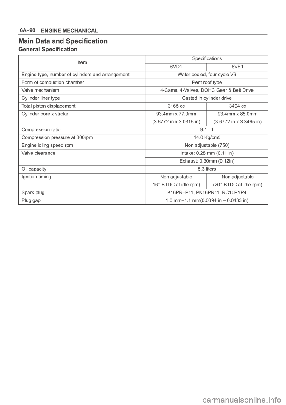
Main Data and Specification
General Specification
ItemSpecificationsItem6VD16VE1
Engine type, number of cylinders and arrangementWater cooled, four cycle V6
Form of combustion chamberPent roof type
Valve mechanism4-Cams, 4-Valves, DOHC Gear & Belt Drive
Cylinder liner typeCasted in cylinder drive
Total piston displacement3165 cc3494 cc
Cylinder bore x stroke93.4mm x 77.0mm93.4mm x 85.0mm
(3.6772 in x 3.0315 in)(3.6772 in x 3.3465 in)
Compression ratio9.1 : 1
Compression pressure at 300rpm14.0 Kg/cm
Engine idling speed rpmNon adjustable (750)
Valve clearanceIntake: 0.28 mm (0.11 in)
Exhaust: 0.30mm (0.12in)
Oil capacity5.3 liters
Ignition timingNon adjustableNon adjustable
16 BTDC at idle rpm)(20 BTDC at idle rpm)
Spark plugK16PR–P11, PK16PR11, RC10PYP4
Plug gap1.0 mm–1.1 mm(0.0394 in – 0.0433 in)
Page 1049 of 6000

6A–93
ENGINE MECHANICAL
Crankshaft main bearing, Flywheel, Crankcase, Oil pan, Timing belt tensioner, Timing pulley, Timing belt
cover, Oil pump, Oil gallery, Oil strainer and Water pump
Nꞏm (Kgꞏm/Ib ft)
E06RW039
Page 1054 of 6000

ENGINE COOLING6B–1
ENGINE
ENGINE COOLING
CONTENTS
Service Precaution 6B–1. . . . . . . . . . . . . . . . . . . . . .
General Description 6B–2. . . . . . . . . . . . . . . . . . . . .
Diagnosis 6B–5. . . . . . . . . . . . . . . . . . . . . . . . . . . . . .
Draining and Refilling Cooling System 6B–6. . . . .
Water Pump 6B–7. . . . . . . . . . . . . . . . . . . . . . . . . . . .
Water Pump and Associated Parts 6B–7. . . . . . .
Removal 6B–7. . . . . . . . . . . . . . . . . . . . . . . . . . . . .
Inspection 6B–7. . . . . . . . . . . . . . . . . . . . . . . . . . . .
Installation 6B–7. . . . . . . . . . . . . . . . . . . . . . . . . . . .
Thermostat 6B–8. . . . . . . . . . . . . . . . . . . . . . . . . . . . .
Thermostat and Associated Parts 6B–8. . . . . . . .
Removal 6B–8. . . . . . . . . . . . . . . . . . . . . . . . . . . . .
Inspection 6B–8. . . . . . . . . . . . . . . . . . . . . . . . . . . . Installation 6B–8. . . . . . . . . . . . . . . . . . . . . . . . . . . .
Radiator 6B–9. . . . . . . . . . . . . . . . . . . . . . . . . . . . . . .
Radiator and Associated Parts 6B–9. . . . . . . . . .
Removal 6B–9. . . . . . . . . . . . . . . . . . . . . . . . . . . . .
Inspection 6B–10. . . . . . . . . . . . . . . . . . . . . . . . . . . .
Installation 6B–11. . . . . . . . . . . . . . . . . . . . . . . . . . . .
Drive Belt and Cooling Fan 6B–12. . . . . . . . . . . . . . .
Drive Belt and Associated Parts 6B–12. . . . . . . . .
Inspection 6B–12. . . . . . . . . . . . . . . . . . . . . . . . . . . .
Installation 6B–12. . . . . . . . . . . . . . . . . . . . . . . . . . . .
Main Data and Specifications 6B–13. . . . . . . . . . . . .
Special Tool 6B–14. . . . . . . . . . . . . . . . . . . . . . . . . . . .
Service Precaution
WARNING: IF SO EQUIPPED WITH A
SUPPLEMENTAL RESTRAINT SYSTEM (SRS),
REFER TO THE SRS COMPONENT AND WIRING
LOCATION VIEW IN ORDER TO DETERMINE
WHETHER YOU ARE PERFORMING SERVICE ON OR
NEAR THE SRS COMPONENTS OR THE SRS
WIRING. WHEN YOU ARE PERFORMING SERVICE
ON OR NEAR THE SRS COMPONENTS OR THE SRS
WIRING, REFER TO THE SRS SERVICE
INFORMATION. FAILURE TO FOLLOW WARNINGS
COULD RESULT IN POSSIBLE AIR BAG
DEPLOYMENT, PERSONAL INJURY, OR
OTHERWISE UNNEEDED SRS SYSTEM REPAIRS.
CAUTION: Always use the correct fastener in the
proper location. When you replace a fastener, use
ONLY the exact part number for that application.
ISUZU will call out those fasteners that require a
replacement after removal. ISUZU will also call out
the fasteners that require thread lockers or thread
sealant. UNLESS OTHERWISE SPECIFIED, do not
use supplemental coatings (Paints, greases, or other
corrosion inhibitors) on threaded fasteners or
fastener joint interfaces. Generally, such coatings
adversely affect the fastener torque and the joint
clamping force, and may damage the fastener. When
you install fasteners, use the correct tightening
sequence and specifications. Following these
instructions can help you avoid damage to parts and
systems.