belt OPEL FRONTERA 1998 Repair Manual
[x] Cancel search | Manufacturer: OPEL, Model Year: 1998, Model line: FRONTERA, Model: OPEL FRONTERA 1998Pages: 6000, PDF Size: 97 MB
Page 1836 of 6000

ENGINE COOLING 6B – 3
WAT E R P U M P
The coolant pump is a centrifugal impeller type and is
driven by V type drive belt.
Legend
(1) Roller Bearing
(2) Ball Bearing
(3) Seal Unit
THERMOSTAT
The thermostat is a wax pellet type with a jiggle valve
and is installed in the thermostat housing.
Legend
(1) Bolt
(2) Thermostat Housing
(3) Thermostat
(4) Intake Manifold
RADIATOR
The radiator is a tube type with corrugated fins. In order
to raise the boiling point of coolant, the radiator is fitted
with a cap in which the valve is operated under the
pressure.
1
3 2
PCD 60
A06RW024
1
2
3
4
032RW002
110RS001
Page 1839 of 6000

6B – 6 ENGINE COOLING
REMOVAL
1. Drain coolant.
2. AC Generator Drive Belt
1) Loosen AC Generator mounting bolt, adjust
plate lock bolt, and remove the drive belt.
3. Cooling Fan Assembly
1) Remove lock nut and take out cooling fan
assembly with cooling fan clutch.
4. Water Pump Assembly
INSPECTION
Make necessary repair and parts replacement if
excessive wear or damage is found during inspection.
Should any of the following problems occur, the entire
water pump assembly must be replaced.
1) Cracks in the water pump body
2) Coolant leakage from the seal unit
3) Excessive play in radial direction or abnormal noise
4) Excessive play in thrust direction
5) Cracks or corrosion in the impeller
INSTALLATION
1. Gasket
1) Set gasket to gear case.
2. Water Pump Assembly
1) Install water pump assembly, and tighten to
specified torque.Torque: 20 Nꞏm (2.0 kgꞏm/14.5 lb ft)
3. Cooling Fan Assembly
1) Install cooling fan assembly, and tighten to
specified torque.
Torque: 8 Nꞏm (0.8 kgꞏm/5.8 lb ft)
4. AC Generator Drive Belt
1) Install AC Generator drive belt and adjust belt
tension.
Torque: 40 Nꞏm (4.1 kgꞏm/29.7 lb ft)
For ACG to bracket
20 Nꞏm (2.0 kgꞏm/14.5 lb ft)
For ACG to adjust plate
5. Fill coolant to specified capacity.
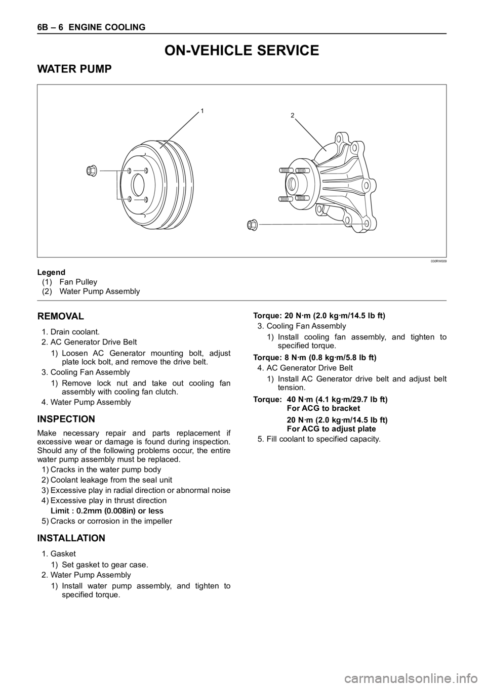
12
Legend
(1) Fan Pulley
(2) Water Pump Assembly
030RW009
ON-VEHICLE SERVICE
WAT E R P U M P
Page 1844 of 6000

ENGINE COOLING 6B – 11
DRIVE BELT ADJUSTMENT
INSPECTION
Check drive belts for wear or damage, and replace with
new ones as necessary. Check belts for tension, and
adjust as necessary.
1) Check drive belt tension.
2) Push the middle of belt with a force of 98 N
(10 kg/22 lb) and check each belt for deflection.
Standard deflection:
For A.C. generator & fan pulley drive belt
Initial tension : 8 – 12 mm (0.31 – 0.47 in)
Tension at readjustment : Same as above.
For A/C compressor drive belt
Initial tension : 7 – 10 mm (0.28 – 0.38 in)
Tension at readjustment : 5 – 8 mm (0.20 – 0.31 in)
TENSION ADJUSTMENT
1) Loosen AC generator mounting bolt to move AC
generator, adjust belt tension and tighten to the
specified torque.
Legend
(1) Crankshaft Pulley
(2) A.C. Generator Pulley
(3) Cooling Fan Pulley
5
3
1 2 4
Legend
(1) Crankshaft Pulley
(2) A.C. Generator
(3) Cooling Fan Pulley
(4) A/C Compressor
(5) Belt Tensioner Pulley
012RW085
3
2
1
012RW084
Page 1845 of 6000

6B – 12 ENGINE COOLING
To r q u e :
For A.C. Generator fixing bolt
40 Nꞏm (4.1 kgꞏm/29.7 lb ft)
For Adjusting plate fixing bolt
24 Nꞏm (2.4 kgꞏm/17.4 lb ft)
For Adjusting plate lock bolt
19 Nꞏm (1.9 kgꞏm/13.7 lb ft)
2) Adjust the A/C compressor drive belt by tightening
the belt tensioner bolt.
Legend
(1) Crankshaft Pulley
(2) A.C. Generator Pulley
(3) Cooling Fan Pulley
(4) A/C Compressor Pulley
(5) Belt Tensioner Pulley
5
3
24
1
012RW110
Page 1860 of 6000

ENGINE FUEL 6C – 15
HIGH PRESSURE OIL PUMP
REMOVAL
1. Disconnect battery ground cable.
2. Remove air cleaner cover and air duct
3. Intercooler assembly
Refer to “Intercooler” in this manual.
4. Remove high pressure oil pipe
5. Timing belt cover
Disconnect CMP sensor cable.
Remove CMP sensor bracket.
6. Tensioner
7. Timing Belt
8. Remove high pressure oil pump timing pulley
9. Remove crankshaft damper pulley
10. Remove timing gear case cover
11. Remove idle gear A
Before removing idle gear A, set two bolts to the
sub gear of idle gear A and turn it to align the teeth
of idle gear A main gear.
Then lock them by bolts as shown in the illustration.Legend
(1) Idle gear A sub gear
(2) Idle gear A main gear
(3) Bar
(4) Lock bolt
1
2
43
Legend
(1) O-Ring
(2) High Pressure Oil Pump Assembly
(3) Nut
(4) O-Ring
040RW007
4 1
2
3
014RW177
Page 1863 of 6000

6C – 18 ENGINE FUEL
4. Remove lock bolt of idle gear A.
5. Install timing gear case cover.
Refer to “Timing gear” in this manual.
6. Install front plate.
Torque: 20 Nꞏm (2.0 kgꞏm/14.5 lb ft)
7. Install timing pulley of high pressure oil pump.
Torque: 10 Nꞏm (1.0 kgꞏm/7.2 lb ft)
8. Install timing belt and tighten timing belt tensioner
assembly.
Refer to “Cylinder head” in this manual.
Legend
(1) Align Mark
(2) Camshaft Pulley
(3) Timing Belt
(4) High Pressure Oil Pump Pulley
(5) Bolt
(6) Tensioner Assembly
(7) Tensioner Bolt
(8) Tensioner Spring
9. Install CMP sensor bracket.
Torque: 20 Nꞏm (2.0 kgꞏm/14.5 lb ft)
10. Connect CMP sensor cable.
11. Install timing belt cover.
Torque: 9 Nꞏm (0.9 kgꞏm/6.5 lb ft)
12. Fill with about 300 cc of engine oil from the high
pressure oil pipe installation port of the oil rail using
an oil filler.
If assembled without filling the oil rail with oil, the
time for engine starting will be longer.
13. Immediately install high pressure oil pipe and
tighten to specified torque.
NOTE:
1) Use new O-ring.
2) Clean O-ring groove and fitting surface of parts.
3) Apply engine oil to O-ring.
Torque: 80 Nꞏm (8.1 kgꞏm/57.9 lb ft)14. Install the crankshaft damper pulley with specified
torque.
Torque: 220 Nꞏm (22 kgꞏm/159 lb ft)
15. Install the intercooler assembly.
Refer to “Intercooler” in this manual.
16. Install air cleaner cover and air duct.
1
2
3
8
67
4 5
F06RW055
Page 1883 of 6000

6D – 16 ENGINE ELECTRICAL
DIAGNOSIS
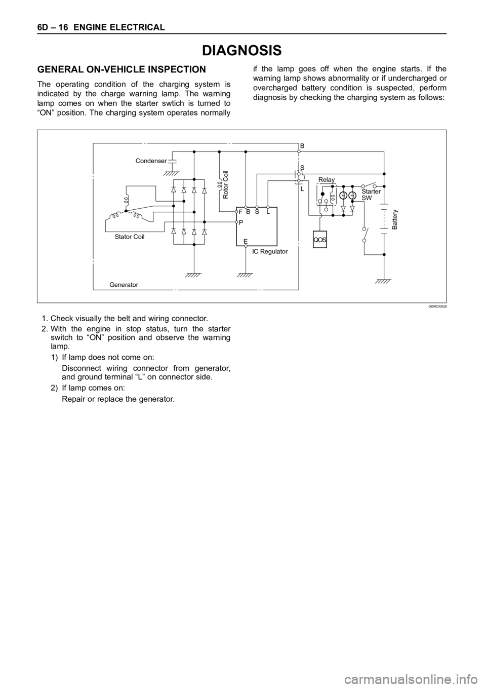
GENERAL ON-VEHICLE INSPECTION
The operating condition of the charging system is
indicated by the charge warning lamp. The warning
lamp comes on when the starter swtich is turned to
“ON” position. The charging system operates normallyif the lamp goes off when the engine starts. If the
warning lamp shows abnormality or if undercharged or
overcharged battery condition is suspected, perform
diagnosis by checking the charging system as follows:
Condenser
GeneratorStator Coil
IC RegulatorStarter
SW
Rotor Coil
Battery
P F
EBS LRelay B
S
L
QOS
065R200028
1. Check visually the belt and wiring connector.
2. With the engine in stop status, turn the starter
switch to “ON” position and observe the warning
lamp.
1) If lamp does not come on:
Disconnect wiring connector from generator,
and ground terminal “L” on connector side.
2) If lamp comes on:
Repair or replace the generator.
Page 1943 of 6000

6E–50
4JX1–TC ENGINE DRIVEABILITY AND EMISSIONS
Engine Cranks But Will Not Run
StepNo Ye s Va l u e ( s ) Action
10Refer to Engine Mechanical Diagnosis to diagnose the
following conditions:
Faulty camshaft drive belts
Leaking or sticky valves or rings
Excessive valve deposits
Weak valve springs
Incorrect valve timing
Leaking head gasket
Is the action complete?
—Verify repairGo to Step 11
11Observe the “Engine Speed” data display on the Tech 2
while cranking the engine.
Is the engine RPM indicated? (If the Tech 2 is normally
powered from the cigarette lighter socket, and if the
Tech 2 display goes blank while cranking the engine, it
will be necessary to power the Tech 2 directly from the
vehicle battery.)
—Go to Step 12Go to Step 17
121. At the ECM (female) side of the connector
mentioned in step, connect a test light between the
ignition + terminal and one of the injector driver
circuits at the same connector.
2. Ignition “ON.”
3. Observe the test light, and repeat the test for each
injector driver circuit by oscilloscope.
Did the test light stay on when checking any of the 4
injector driver circuits?
—Go to Step 13Go to Step 15
131. Ignition “OFF,” disconnect the ECM.
2. Ignition “ON,” observe the test light.
Is the test light “ON?”
—Go to Step 14Go to Step 16
14Locate and repair the short to ground in the injector
driver circuit.
Is the action complete?
—Verify repair—
15Check for an open injector driver circuit.
Was a problem found?
—Verify repairGo to Step 16
16Replace the ECM (Refer to the Data Programming in
Case of ECM change).
Is the action complete?
—Verify repair—
171. Raise the vehicle and disconnect the CKP sensor
harness.
2. Ignition “ON.”
3. With a test light to ground, probe the harness
ignition feed terminal.
Did the light illuminate?
—Go to Step 19Go to Step 18
18Check the ignition feed wire between the sensor and
the ECM for a short to ground or open circuit.
Is the action complete?
—Verify repair—
Page 2071 of 6000

6E–178
4JX1–TC ENGINE DRIVEABILITY AND EMISSIONS
Hard Start Symptom
StepNo Ye s Va l u e ( s ) Action
121. Check the battery voltage.
2. If a problem is found, repair as necessary.
Was a problem found?
—Verify repairGo to Step 13
131. Check for the following engine mechanical
problems (Refer to
Engine Mechanical):
Low compression
Leaking cylinder head gaskets
Worn or incorrect camshaft
Camshaft drive belt slipped or stripped
2. If a problem is found, repair as necessary.
Was a problem found?
—Verify repairGo to Step 14
141. Review all diagnostic procedures within this table.
2. If all procedures have been completed and no
malfunctions have been found, review/inspect the
following:
Visual/physical inspection
Tech–2 data
Freeze Frame data/Failure Records buffer
All electrical connections within a suspected
circuit and/or system.
3. If a problem is found, repair as necessary.
Was a problem found?
—Verify repair
Contact
Te c h n i c a l
Assistance
Page 2075 of 6000

6E–182
4JX1–TC ENGINE DRIVEABILITY AND EMISSIONS
Lack of Power, Sluggish or Spongy Symptom
StepNo Ye s Va l u e ( s ) Action
111. Check for an engine mechanical problem. Check
for low compression, incorrect or worn camshaft,
loose timing belt, etc. Refer to
Engine Mechanical.
2. If a problem is found, repair as necessary.
Was a problem found?
—Verify repairGo to Step 12
121. Review all diagnostic procedures within this table.
2. If all procedures have been completed and no
malfunctions have been found, review/inspect the
following:
Visual/physical inspection
Te c h 2 d a t a
Freeze Frame data/Failure Records buffer
All electrical connections within a suspected
circuit and/or system.
3. If a problem is found, repair as necessary.
Was a problem found?
—Verify repair
Contact
Te c h n i c a l
Assistance