direction OPEL FRONTERA 1998 Owner's Manual
[x] Cancel search | Manufacturer: OPEL, Model Year: 1998, Model line: FRONTERA, Model: OPEL FRONTERA 1998Pages: 6000, PDF Size: 97 MB
Page 1022 of 6000

6A–66
ENGINE MECHANICAL
Limit : 0.12 mm (0.0047 mm)
014RW035
Reassembly
1. Install camshaft drive gear assembly and tighten
three bolts to specified torque.
Torque: 10 Nꞏm (1.0 Kgꞏm/89 lb in)
2. Tighten sub gear setting bolt.
1. Use 5–8840–2443–0 to turn sub gear to right
direction until the M5 bolt hole aligns between
camshaft driven gear and sub gear.
2. Tighten M5 bolt suitable torque for prevent
moving the sub gear.
014RW041
3. Install camshaft assembly and camshaft brackets,
tighten twenty bolts on one side bank to the specified
torque.
1. Apply engine oil to camshaft journal and bearing
surface of camshaft bracket.2. Align timing mark on intake camshaft (one dot for
right bank, two dots for left bank) and exhaust
camshaft (one dot for right bank, two dots for left
bank) to timing mark on camshaft drive gear (one
dot).
014RW020
Legend
(1) Intake Camshaft Timing Gear for Right Bank
(2) Intake Camshaft Timing Gear for Left Bank
(3) Exhaust Camshaft Timing Gear
(4) Discerning Mark
LI: Left Bank Intake
RI: Right Bank Intake
LE: Left Bank Exhaust
RE: Right Bank Exhaust
Page 1036 of 6000
6A–80
ENGINE MECHANICAL
015RS026
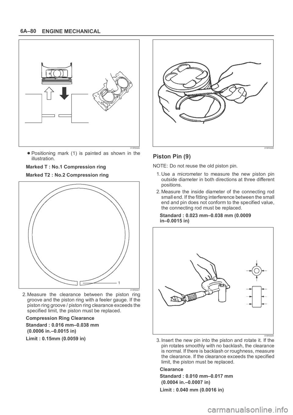
Positioning mark (1) is painted as shown in the
illustration.
Marked T : No.1 Compression ring
Marked T2 : No.2 Compression ring
015RS027
2. Measure the clearance between the piston ring
groove and the piston ring with a feeler gauge. If the
piston ring groove / piston ring clearance exceeds the
specified limit, the piston must be replaced.
Compression Ring Clearance
Standard : 0.016 mm–0.038 mm
(0.0006 in.–0.0015 in)
Limit : 0.15mm (0.0059 in)
015RS028
Piston Pin (9)
NOTE: Do not reuse the old piston pin.
1. Use a micrometer to measure the new piston pin
outside diameter in both directions at three different
positions.
2. Measure the inside diameter of the connecting rod
small end. If the fitting interference between the small
end and pin does not conform to the specified value,
the connecting rod must be replaced.
Standard : 0.023 mm–0.038 mm (0.0009
in–0.0015 in)
015RS029
3. Insert the new pin into the piston and rotate it. If the
pin rotates smoothly with no backlash, the clearance
is normal. If there is backlash or roughness, measure
the clearance. If the clearance exceeds the specified
limit, the piston must be replaced.
Clearance
Standard : 0.010 mm–0.017 mm
(0.0004 in.–0.0007 in)
Limit : 0.040 mm (0.0016 in)
Page 1042 of 6000

6A–86
ENGINE MECHANICAL
11. Remove rear oil seal retainer assembly.
12. Remove main bearing cap.
13. Remove crankshaft.
14. Remove cylinder block.
Inspection and Repair
1. Remove the cylinder head gasket and any other
material adhering to the upper surface of the cylinder
block. Be very careful not to allow any material to
accidentally drop into the cylinder block. Be very
careful not to scratch the cylinder block.
2. Carefully remove the oil pump, rear oil seal retainer,
and crankcase assembly installation surface seal.
3. Wipe the cylinder block clean.
4. Visually inspect the cylinder block. If necessary, use a
flaw detector to perform a dye penetrate and
hydraulic (or air pressure) test. If cracking or other
damage is discovered, the cylinder block must either
be repaired or replaced.
Flatness
1. Using a straight–edge and feeler gauge, check that
the upper surface of the cylinder block is not warped.
CAUTION: Be very careful not to allow any material
to accidentally drop into the upper surface of the
cylinder block. Be very careful not to scratch the
upper surface of the cylinder block.
2. The cylinder block must be reground or replaced if the
warpage exceeds the limit.
Warpage
Limit : 0.15 mm (0.0059 in)
Maximum repairable limit: 0.15 mm (0.0059 in)
012RS004
Cylinder Bore
Use a cylinder gauge to measure the cylinder bore
diameter in both the axial and thrust directions. Each
measurement should be made at six points.CAUTION: Be very careful not to allow any material
to accidentally drop into the upper surface of the
cylinder block. Be very careful not to scratch the
upper surface of the cylinder block.
Cylinder Bore Inside Diameter
Limit : 93.530 (3.6823)
If the measurement exceed the specified limit, the
cylinder block must be replaced.
Diameter
Grade A : 93.400 mm–93.410 mm
(3.6772 in–3.6776 in)
Grade B : 93.411 mm–93.420 mm
(3.6776 in–3.6779 in)
Grade C : 93.421 mm–93.430 mm
(3.6780 in–3.6783 in)
012RS005
NOTE: For information on piston diameter, please refer
to the section ”Inspection of the Piston and Connecting
Rod Assembly” in this manual.
The ”Grade” mark (1) is stamped at the position
illustrated.
Page 1065 of 6000

6B–12
ENGINE COOLING
Drive Belt and Cooling Fan
Drive Belt and Associated Parts
015RW005
Legend
(1) Crankshaft Pulley
(2) Generator
(3) Power Steering Pump(4) Water Pump and Cooling Fan Pulley
(5) Idle Pulley
(6) Tension Pulley
(7) Drive Belt
The drive belt adjustment is not required as automatic
drive belt tensioner is equipped.
Inspection
Check drive belt for wear or damage, and replace with a
new one as necessary.
Installation
Install cooling fan assembly and tighten bolts/nuts to the
specified torque.
Torque : 22 Nꞏm (2.2 Kgꞏm/16 lb ft) for fan pulley
and fan bracket.
Torque : 10 Nꞏm (1.0 Kgꞏm/88.5 lb in) for fan and
clutch assembly.
NOTE: Fan belts for 6VE1 Gasoline Engine mounted on
98MY (UX) have been brought into one. As a result, the
rotating direction of a fan belt is opposite to the direction
o f c o o l i n g f a n f o r 9 2 t o 9 7 M Y 6 V D 1 w i t h n o
interchangeability.
Therefore, incorrect installation of a fan may cause the air
for cooling to flow in the opposite direction, this resulting
in the poor performance of the air-conditioner and a rise
temperature in engine cooling water.
Page 1072 of 6000
6C–5
ENGINE FUEL
Installation
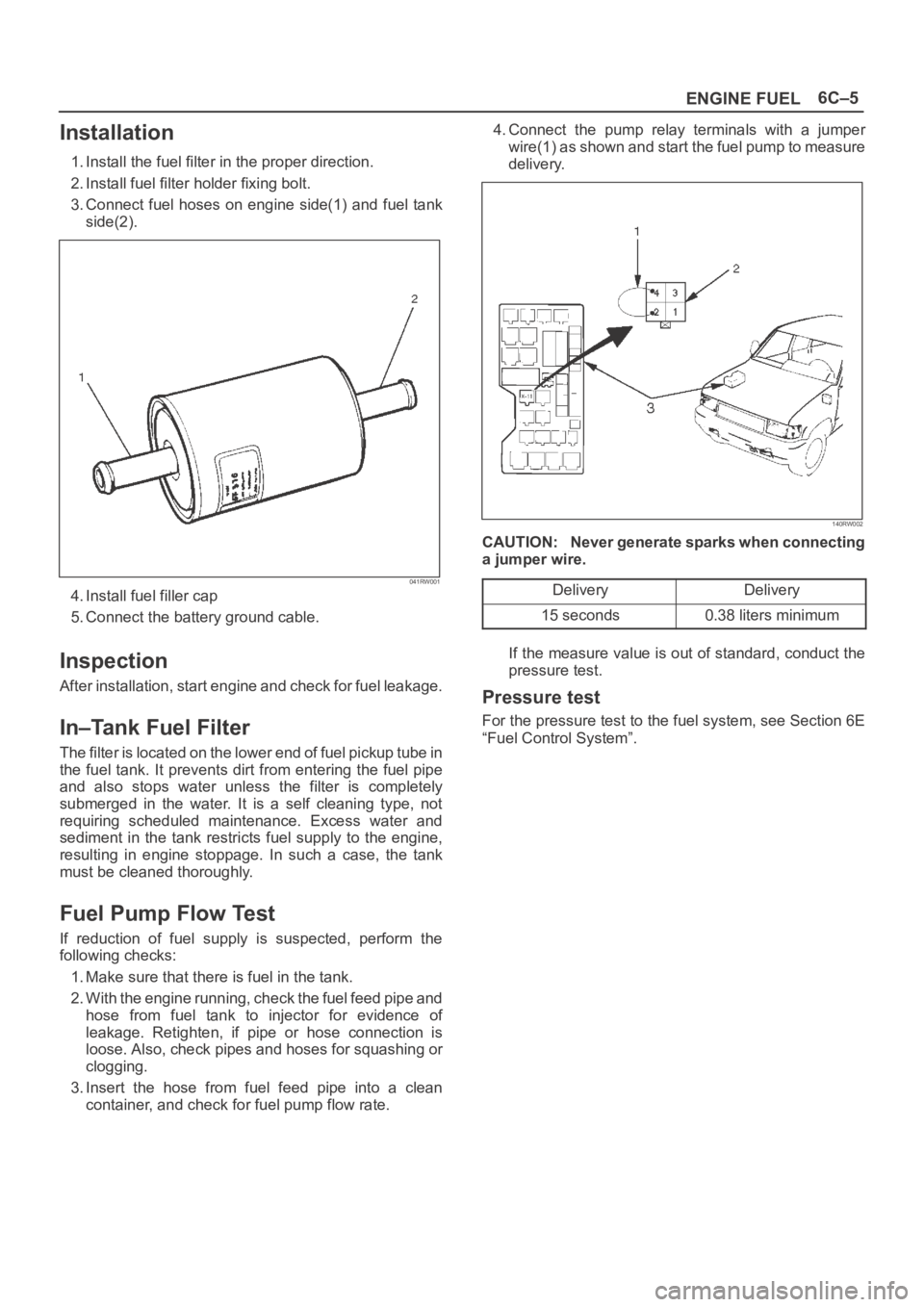
1. Install the fuel filter in the proper direction.
2. Install fuel filter holder fixing bolt.
3. Connect fuel hoses on engine side(1) and fuel tank
side(2).
041RW001
4. Install fuel filler cap
5. Connect the battery ground cable.
Inspection
After installation, start engine and check for fuel leakage.
In–Tank Fuel Filter
The filter is located on the lower end of fuel pickup tube in
the fuel tank. It prevents dirt from entering the fuel pipe
and also stops water unless the filter is completely
submerged in the water. It is a self cleaning type, not
requiring scheduled maintenance. Excess water and
sediment in the tank restricts fuel supply to the engine,
resulting in engine stoppage. In such a case, the tank
must be cleaned thoroughly.
Fuel Pump Flow Test
If reduction of fuel supply is suspected, perform the
following checks:
1. Make sure that there is fuel in the tank.
2. With the engine running, check the fuel feed pipe and
hose from fuel tank to injector for evidence of
leakage. Retighten, if pipe or hose connection is
loose. Also, check pipes and hoses for squashing or
clogging.
3. Insert the hose from fuel feed pipe into a clean
container, and check for fuel pump flow rate.4. Connect the pump relay terminals with a jumper
wire(1) as shown and start the fuel pump to measure
delivery.
140RW002
CAUTION: Never generate sparks when connecting
a jumper wire.
Delivery
Delivery
15 seconds0.38 liters minimum
If the measure value is out of standard, conduct the
pressure test.
Pressure test
For the pressure test to the fuel system, see Section 6E
“Fuel Control System”.
Page 1083 of 6000

6D1–4
ENGINE ELECTRICAL
4. Attach one end of the remaining cable to the negative
terminal of the booster battery.
Attach the other end of the same cable to a solid
engine ground (such as the air conditioning
compressor bracket or the generator mounting
bracket) of the vehicle with the discharged battery.
The ground connection must be at least 450 mm (18
in.) from the battery of the vehicle whose battery is
being charged.
WARNING: NEVER ATTACH THE END OF THE
JUMPER CABLE DIRECTLY TO THE NEGATIVE
TERMINAL OF THE DEAD BATTERY.
5. Start the engine of the vehicle with the good battery.
Make sure that all unnecessary electrical accessories
have been turned “OFF”.
6. Start the engine of the vehicle with the dead battery.
7. To remove the jumper cables, follow the above
directions in reverse order.
Be sure to first disconnect the negative cable from the
vehicle with the discharged battery.
Battery Removal
061RS002
1. Remove negative cable (1).
2. Remove positive cable (2).
3. Remove retainer screw and rods (3).
4. Remove retainer (4).
5. Remove battery (5).
Battery Installation
1. Install battery (5).
2. Install retainer (4).
3. Instal retainer screw and rods (3).
NOTE: Make sure that the rod is hooked on the body
side.
4. Install positive cable (2).
5. Install negative cable (1).
Page 1103 of 6000
6D3–12STARTING AND CHARGING SYSTEM
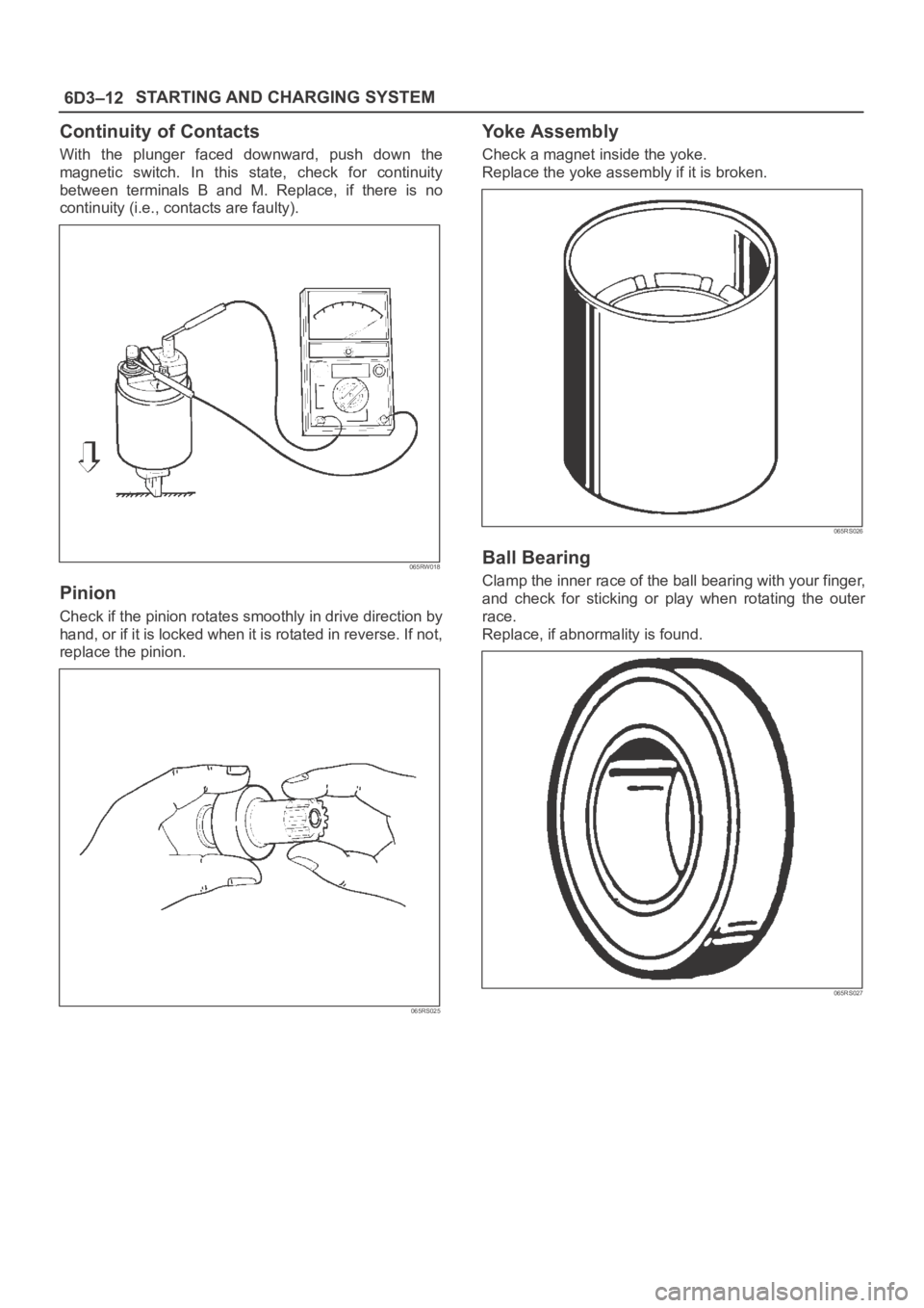
Continuity of Contacts
With the plunger faced downward, push down the
magnetic switch. In this state, check for continuity
between terminals B and M. Replace, if there is no
continuity (i.e., contacts are faulty).
065RW018
Pinion
Check if the pinion rotates smoothly in drive direction by
hand, or if it is locked when it is rotated in reverse. If not,
replace the pinion.
065RS025
Yoke Assembly
Check a magnet inside the yoke.
Replace the yoke assembly if it is broken.
065RS026
Ball Bearing
Clamp the inner race of the ball bearing with your finger,
and check for sticking or play when rotating the outer
race.
Replace, if abnormality is found.
065RS027
Page 1104 of 6000
6D3–13 STARTING AND CHARGING SYSTEM
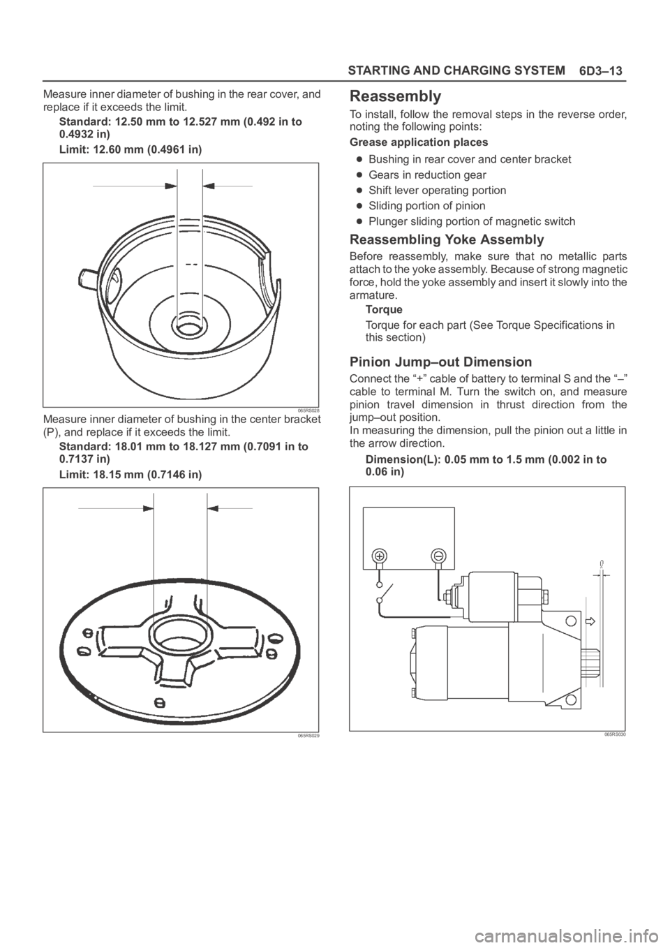
Measure inner diameter of bushing in the rear cover, and
replace if it exceeds the limit.
Standard: 12.50 mm to 12.527 mm (0.492 in to
0.4932 in)
Limit: 12.60 mm (0.4961 in)
065RS028Measure inner diameter of bushing in the center bracket
(P), and replace if it exceeds the limit.
Standard: 18.01 mm to 18.127 mm (0.7091 in to
0.7137 in)
Limit: 18.15 mm (0.7146 in)
065RS029
Reassembly
To install, follow the removal steps in the reverse order,
noting the following points:
Grease application places
Bushing in rear cover and center bracket
Gears in reduction gear
Shift lever operating portion
Sliding portion of pinion
Plunger sliding portion of magnetic switch
Reassembling Yoke Assembly
Before reassembly, make sure that no metallic parts
attach to the yoke assembly. Because of strong magnetic
force, hold the yoke assembly and insert it slowly into the
armature.
To r q u e
Torque for each part (See Torque Specifications in
this section)
Pinion Jump–out Dimension
Connect the “+” cable of battery to terminal S and the “–”
cable to terminal M. Turn the switch on, and measure
pinion travel dimension in thrust direction from the
jump–out position.
In measuring the dimension, pull the pinion out a little in
the arrow direction.
Dimension(L): 0.05 mm to 1.5 mm (0.002 in to
0.06 in)
065RS030
Page 1106 of 6000
6D3–15 STARTING AND CHARGING SYSTEM
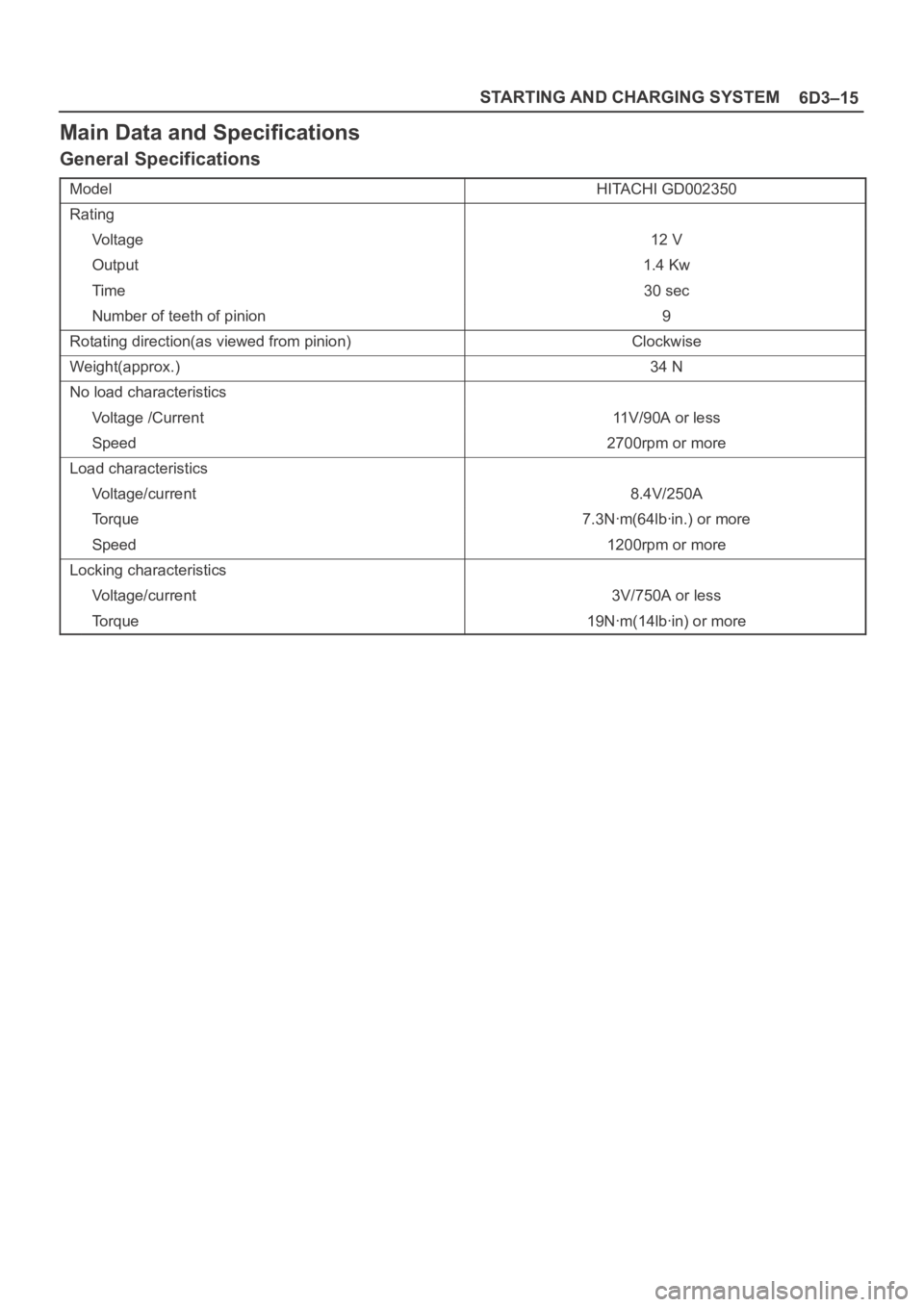
Main Data and Specifications
General Specifications
ModelHITACHI GD002350
Rating
Voltage12 V
Output1.4 Kw
Time30 sec
Number of teeth of pinion 9
Rotating direction(as viewed from pinion)Clockwise
Weight(approx.)34 N
No load characteristics
Voltage /Current 11V/90A or less
Speed 2700rpm or more
Load characteristics
Voltage/current 8.4V/250A
Torque 7.3Nꞏm(64lbꞏin.) or more
Speed 1200rpm or more
Locking characteristics
Voltage/current 3V/750A or less
To r q u e19Nꞏm(14lbꞏin) or more
Page 1115 of 6000
6D3–24STARTING AND CHARGING SYSTEM
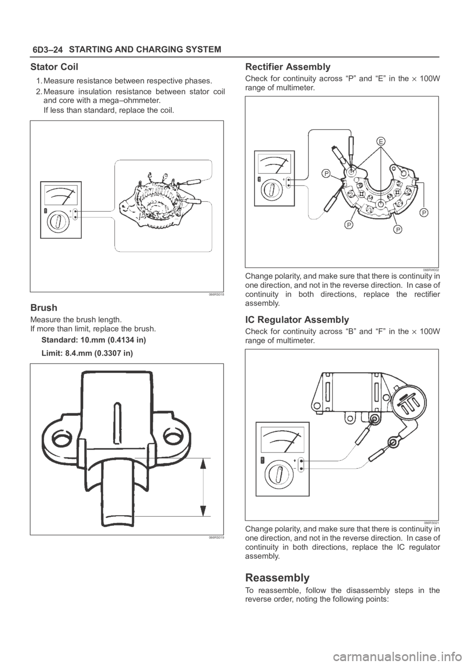
Stator Coil
1. Measure resistance between respective phases.
2. Measure insulation resistance between stator coil
and core with a mega–ohmmeter.
If less than standard, replace the coil.
066RS018
Brush
Measure the brush length.
If more than limit, replace the brush.
Standard: 10.mm (0.4134 in)
Limit: 8.4.mm (0.3307 in)
066RS019
Rectifier Assembly
Check for continuity across “P” and “E” in the 100W
range of multimeter.
066RW002Change polarity, and make sure that there is continuity in
one direction, and not in the reverse direction. In case of
continuity in both directions, replace the rectifier
assembly.
IC Regulator Assembly
Check for continuity across “B” and “F” in the 100W
range of multimeter.
066RS021Change polarity, and make sure that there is continuity in
one direction, and not in the reverse direction. In case of
continuity in both directions, replace the IC regulator
assembly.
Reassembly
To reassemble, follow the disassembly steps in the
reverse order, noting the following points: