direction OPEL FRONTERA 1998 Service Manual
[x] Cancel search | Manufacturer: OPEL, Model Year: 1998, Model line: FRONTERA, Model: OPEL FRONTERA 1998Pages: 6000, PDF Size: 97 MB
Page 1839 of 6000
6B – 6 ENGINE COOLING
REMOVAL
1. Drain coolant.
2. AC Generator Drive Belt
1) Loosen AC Generator mounting bolt, adjust
plate lock bolt, and remove the drive belt.
3. Cooling Fan Assembly
1) Remove lock nut and take out cooling fan
assembly with cooling fan clutch.
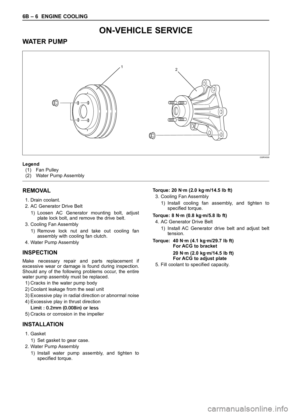
4. Water Pump Assembly
INSPECTION
Make necessary repair and parts replacement if
excessive wear or damage is found during inspection.
Should any of the following problems occur, the entire
water pump assembly must be replaced.
1) Cracks in the water pump body
2) Coolant leakage from the seal unit
3) Excessive play in radial direction or abnormal noise
4) Excessive play in thrust direction
5) Cracks or corrosion in the impeller
INSTALLATION
1. Gasket
1) Set gasket to gear case.
2. Water Pump Assembly
1) Install water pump assembly, and tighten to
specified torque.Torque: 20 Nꞏm (2.0 kgꞏm/14.5 lb ft)
3. Cooling Fan Assembly
1) Install cooling fan assembly, and tighten to
specified torque.
Torque: 8 Nꞏm (0.8 kgꞏm/5.8 lb ft)
4. AC Generator Drive Belt
1) Install AC Generator drive belt and adjust belt
tension.
Torque: 40 Nꞏm (4.1 kgꞏm/29.7 lb ft)
For ACG to bracket
20 Nꞏm (2.0 kgꞏm/14.5 lb ft)
For ACG to adjust plate
5. Fill coolant to specified capacity.
12
Legend
(1) Fan Pulley
(2) Water Pump Assembly
030RW009
ON-VEHICLE SERVICE
WAT E R P U M P
Page 1870 of 6000

ENGINE ELECTRICAL 6D – 3
ON-VEHICLE SERVICE
BATTERY CHARGING
Observe the following safety precautions when
charging the battery:
1. Never attempt to charge the battery when the fluid
level is below the lower level line on the side of the
battery. In this case, the battery must be replaced.
2. Pay close attention to the battery during the
charging procedure.
Battery charging should be discontinued or the rate
of charge reduced if the battery feels hot to the
touch.
Battery charging should be discontinued or the rate
of charge reduced if the battery begins to gas or
spew electrolyte from the vent holes.
3. In order to more easily view the hydrometer blue
dot or ring, it may be necessary to jiggle or tilt the
battery.
4. Battery temperature can have a great effect on
battery charging capacity.
5. The sealed battery used on this vehicle may be
either quick-charged or slow-charged in the same
manner as other batteries.
Whichever method you decide to use, be sure that
you completely charge the battery. Never partially
charge the battery.
JUMP STARTING
JUMP STARTING WITH AN AUXILIARY
(BOOSTER) BATTERY
CAUTION: Never push or tow the vehicle in an
attempt to start it. Serious damage to the emission
system as well as other vehicle parts will result.
Treat both the discharged battery and the booster
battery with great care when using jumper cables.
Carefully follow the jump starting procedure, being
careful at all times to avoid sparking.
WARNING: Failure to carefully follow the jump
starting procedure could result in the following:
1. Serious personal injury, particularly to your
eyes.
2. Property damage from a battery explosion,
battery acid, or an electrical fire.
3. Damage to the electronic components of one or
both vehicles.
Never expose the battery to an open flame or electrical
spark. Gas generated by the battery may catch fire or
explode. Remove any rings, watches, or other jewelry
before working around the battery. Protect your eyes by
wearing an approved set of goggles.
Never allow battery fluid to come in contact with your
eyes or skin.
Never allow battery fluid to come in contact with fabrics
or painted surfaces.
Battery fluid is a highly corrosive acid.Should battery fluid come in contact with your eyes,
skin, fabric, or a painted surface, immediately and
thoroughly rinse the affected area with clean tap water.
Never allow metal tools or jumper cables to come in
contact with the positive battery terminal, or any other
metal surface of the vehicle. This will protect against a
short circuit.
Always keep batteries out of the reach of young
children.
JUMP STARTING PROCEDURE
1. Set the vehicle parking brake.
If the vehicle is equipped with an automatic
transmission, place the selector lever in the “PARK”
position.
If the vehicle is equipped with a manual
transmission place the shift lever in the “NEUTRAL”
position.
Turn “OFF” the ignition.
Turn “OFF” all lights and any other accessory
requiring electrical power.
2. Look at the built-in hydrometer.
If the indication area of the built-in hydrometer is
completely clear, do not try to jump start.
3. Attach the end of one jumper cable to the positive
terminal of the booster battery.
Attach the other end of the same cable to the
positive terminal of the discharged battery.
Do not allow the vehicles to touch each other.
This will cause a ground connection, effectively
neutralizing the charging procedure.
Be sure that the booster battery has a 12 volt rating.
4. Attach one end of the remaining cable to the
negative terminal of the booster battery.
Attach the other end of the same cable to a solid
engine ground (such as the A/C compressor
bracket or the generator mounting bracket) of the
vehicle with the discharged battery.
This ground connection must be at least 450 mm
(18 in) from the battery of the vehicle whose battery
is being charged.
WARNING: Never attach the end of the jumper
cable directly to the negative terminal of the dead
battery.
5. Start the engine of the vehicle with the good battery.
Make sure that all unnecessary electrical
accessories have been turned “OFF”.
6. Start the engine of the vehicle with the dead battery.
7. To remove the jumper cables, follow the above
directions in the reverse order.
Be sure to first disconnect the negative cable from
the vehicle with the discharged battery.
Page 1880 of 6000
ENGINE ELECTRICAL 6D – 13
Pinion
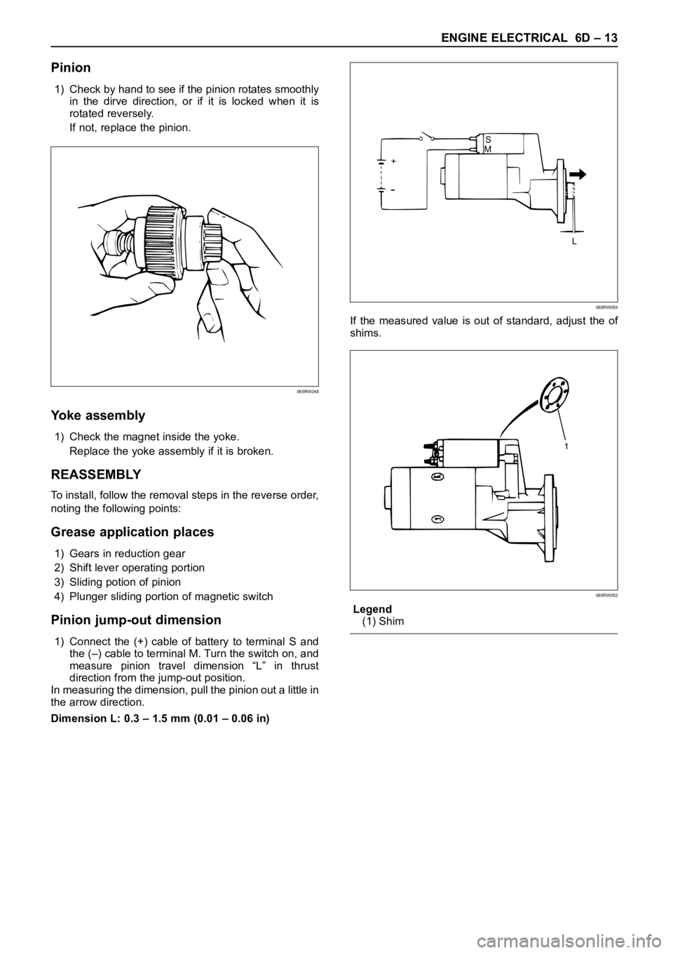
1) Check by hand to see if the pinion rotates smoothly
in the dirve direction, or if it is locked when it is
rotated reversely.
If not, replace the pinion.
Yoke assembly
1) Check the magnet inside the yoke.
Replace the yoke assembly if it is broken.
REASSEMBLY
To install, follow the removal steps in the reverse order,
noting the following points:
Grease application places
1) Gears in reduction gear
2) Shift lever operating portion
3) Sliding potion of pinion
4) Plunger sliding portion of magnetic switch
Pinion jump-out dimension
1) Connect the (+) cable of battery to terminal S and
the (–) cable to terminal M. Turn the switch on, and
measure pinion travel dimension “L” in thrust
direction from the jump-out position.
In measuring the dimension, pull the pinion out a little in
the arrow direction.
Dimension L: 0.3 – 1.5 mm (0.01 – 0.06 in)If the measured value is out of standard, adjust the of
shims.
Legend
(1) Shim
065RW048
S
+
L M
065RW054
1
065RW053
Page 1888 of 6000
ENGINE ELECTRICAL 6D – 21
Rectifier Assembly
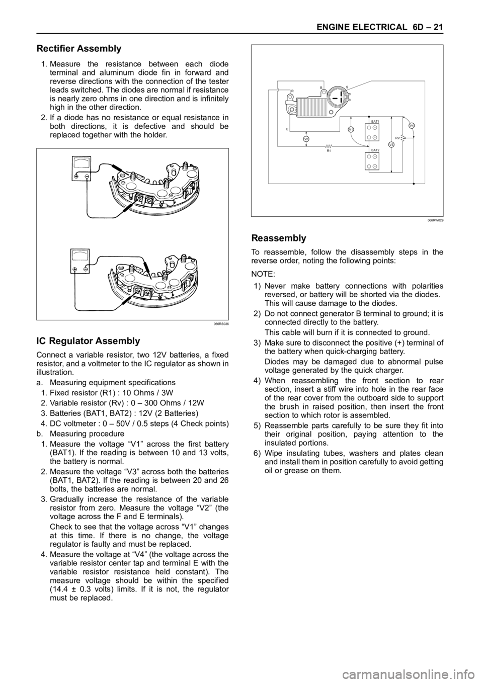
1. Measure the resistance between each diode
terminal and aluminum diode fin in forward and
reverse directions with the connection of the tester
leads switched. The diodes are normal if resistance
is nearly zero ohms in one direction and is infinitely
high in the other direction.
2. If a diode has no resistance or equal resistance in
both directions, it is defective and should be
replaced together with the holder.
IC Regulator Assembly
Connect a variable resistor, two 12V batteries, a fixed
resistor, and a voltmeter to the IC regulator as shown in
illustration.
a. Measuring equipment specifications
1. Fixed resistor (R1) : 10 Ohms / 3W
2. Variable resistor (Rv) : 0 – 300 Ohms / 12W
3. Batteries (BAT1, BAT2) : 12V (2 Batteries)
4. DC voltmeter : 0 – 50V / 0.5 steps (4 Check points)
b. Measuring procedure
1. Measure the voltage “V1” across the first battery
(BAT1). If the reading is between 10 and 13 volts,
the battery is normal.
2. Measure the voltage “V3” across both the batteries
(BAT1, BAT2). If the reading is between 20 and 26
bolts, the batteries are normal.
3. Gradually increase the resistance of the variable
resistor from zero. Measure the voltage “V2” (the
voltage across the F and E terminals).
Check to see that the voltage across “V1” changes
at this time. If there is no change, the voltage
regulator is faulty and must be replaced.
4. Measure the voltage at “V4” (the voltage across the
variable resistor center tap and terminal E with the
variable resistor resistance held constant). The
measure voltage should be within the specified
(14.4 ± 0.3 volts) limits. If it is not, the regulator
must be replaced.
Reassembly
To reassemble, follow the disassembly steps in the
reverse order, noting the following points:
NOTE:
1) Never make battery connections with polarities
reversed, or battery will be shorted via the diodes.
This will cause damage to the diodes.
2) Do not connect generator B terminal to ground; it is
connected directly to the battery.
This cable will burn if it is connected to ground.
3) Make sure to disconnect the positive (+) terminal of
the battery when quick-charging battery.
Diodes may be damaged due to abnormal pulse
voltage generated by the quick charger.
4) When reassembling the front section to rear
section, insert a stiff wire into hole in the rear face
of the rear cover from the outboard side to support
the brush in raised position, then insert the front
section to which rotor is assembled.
5) Reassemble parts carefully to be sure they fit into
their original position, paying attention to the
insulated portions.
6) Wipe insulating tubes, washers and plates clean
and install them in position carefully to avoid getting
oil or grease on them.
066RS036
R
EBS
R1RV
BAT2 BAT1
V2V3
V4V1+
−
+
−
066RW029
Page 1889 of 6000

6D – 22 ENGINE ELECTRICAL
1. Using a press with a socket wrench attached,
reassemble rotor and rear end cover assembly in
the front cover.2. Install pulley on the rotor.
Secure the pulley directly in the vise between two
copper plates, and tighten nut to the specified
torque.
Torque: 111 Nꞏm (82 lb ft)
066RS022
066RS010
MAIN DATA AND SPECIFICATIONS
General Specifications
Model LR190-750B LR-1100-731
Battery voltage V 12
Rated output A 90 100
Direction of rotation Clockwise
(as viewed from pulley side)
Rated rotation speed rpm 5,000
Maximum speed rpm 18,000
Page 2182 of 6000
7A–28
AUTOMATIC TRANSMISSION (4L30–E)
Removal
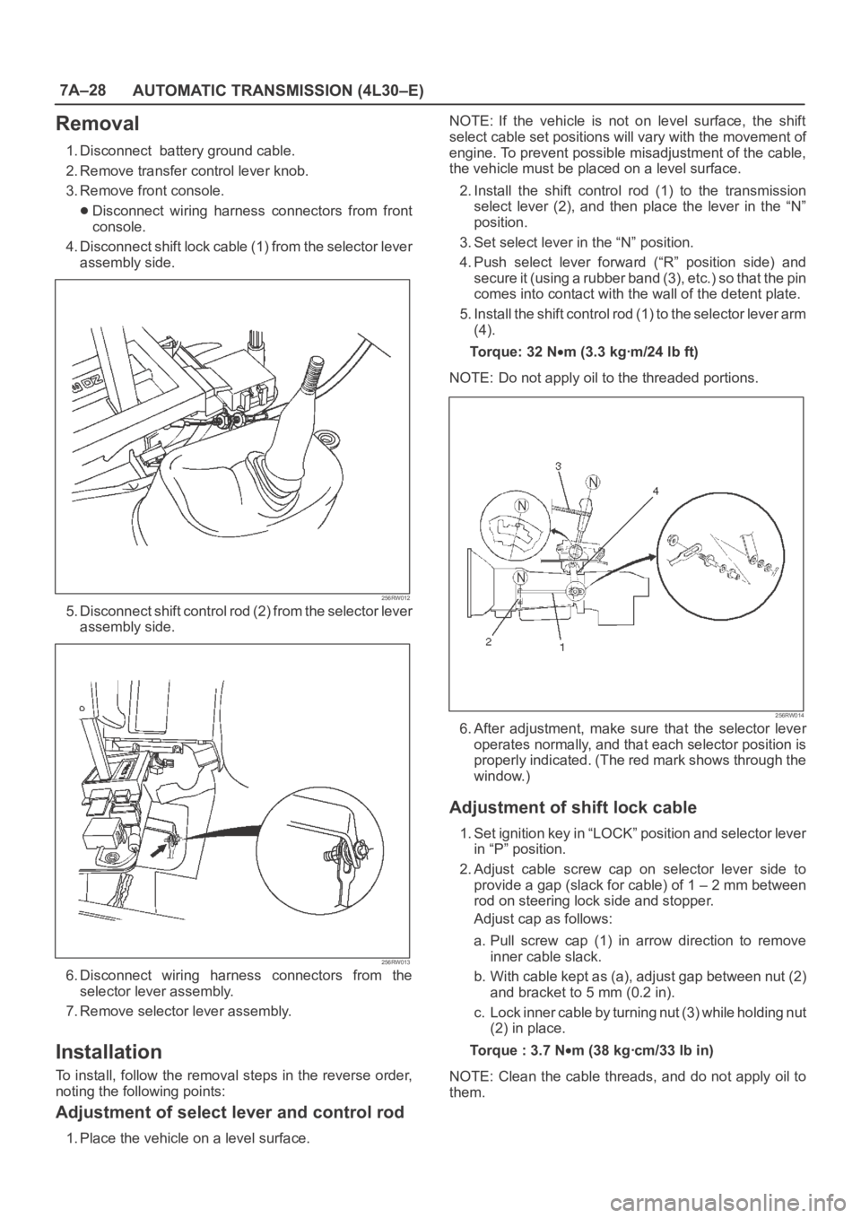
1. Disconnect battery ground cable.
2. Remove transfer control lever knob.
3. Remove front console.
Disconnect wiring harness connectors from front
console.
4. Disconnect shift lock cable (1) from the selector lever
assembly side.
256RW012
5. Disconnect shift control rod (2) from the selector lever
assembly side.
256RW013
6. Disconnect wiring harness connectors from the
selector lever assembly.
7. Remove selector lever assembly.
Installation
To install, follow the removal steps in the reverse order,
noting the following points:
Adjustment of select lever and control rod
1. Place the vehicle on a level surface.NOTE: If the vehicle is not on level surface, the shift
select cable set positions will vary with the movement of
engine. To prevent possible misadjustment of the cable,
the vehicle must be placed on a level surface.
2. Install the shift control rod (1) to the transmission
select lever (2), and then place the lever in the “N”
position.
3. Set select lever in the “N” position.
4. Push select lever forward (“R” position side) and
s e c u r e i t ( u s i n g a r u b b e r b a n d ( 3 ) , e t c . ) s o t h a t t h e p i n
comes into contact with the wall of the detent plate.
5. Install the shift control rod (1) to the selector lever arm
(4).
To r q u e : 3 2 N
m (3.3 kgꞏm/24 lb ft)
NOTE: Do not apply oil to the threaded portions.
256RW014
6. After adjustment, make sure that the selector lever
operates normally, and that each selector position is
properly indicated. (The red mark shows through the
window.)
Adjustment of shift lock cable
1. Set ignition key in “LOCK” position and selector lever
in “P” position.
2. Adjust cable screw cap on selector lever side to
provide a gap (slack for cable) of 1 – 2 mm between
rod on steering lock side and stopper.
Adjust cap as follows:
a. Pull screw cap (1) in arrow direction to remove
inner cable slack.
b. With cable kept as (a), adjust gap between nut (2)
and bracket to 5 mm (0.2 in).
c. Lock inner cable by turning nut (3) while holding nut
(2) in place.
Torque : 3.7 N
m (38 kgꞏcm/33 lb in)
NOTE: Clean the cable threads, and do not apply oil to
them.
Page 2184 of 6000

7A–30
AUTOMATIC TRANSMISSION (4L30–E)
249RW001
Procedure 2
a. Place selector lever in neutral.
b. Disconnect transmission harness connector from
mode switch connector.
c. Remove mode switch connector with bracket from
the transmission case.
d. Connect multimeter (resistance mode) to
terminals 1(E) and 4(H) on mode switch connector.
e. Loosen two mounting screws.
f. Rotate mode switch slightly in both directions to
determine the range (approx. 5 degrees) of
electrical contact.
g. Position mode switch in middle of contact range.
h. Tighten two mounting screws.
i. Remove multimeter and install mode switch
harness connector with bracket to the
transmission case.
j. Connect transmission harness connector to mode
switch connector.
F07RW003
Page 2230 of 6000

7A–76
AUTOMATIC TRANSMISSION (4L30–E)
2. Install the 5–8840–2269–0 (J–38555) inner installer
on the drum (14).
Pre–install piston assembly into 5–8840–2269–0
(J–38555) outer installer.
Install overrun clutch piston assembly (13). Use the
outer installer while pushing piston into drum (14).
Remove the installer.
252RW012
252RW013
3. Install diaphragm spring (12).
4. Install overrun clutch release spring retainer (11) (lip
faces upwards), overrun roller clutch assembly (10),
and cam (9).
5. Place snap ring loosely on spring retainer.
Hold the 5–8840–2275–0 (J–23327–91)
compressor in a vise and compress piston return
spring with compressor.
Set snap ring (8) in ring groove.
Remove the compressor.
6. Install clutch plates (7), start with steel plate and
alternate with lined plates.
7. Install backing plate (6). 8. Install snap ring (5).
9. Install overdrive sun gear with countersink pointing
downwards.
10. Install the overdrive carrier assembly (2).
NOTE: Tu r n t h e a s s e m b l y i n a c o u n t e r – c l o c k w i s e
direction only until roller clutch enters the outer race.
After installation, rotate the assembly and listen for loose
rollers.
11. Install turbine shaft (4) and snap ring (1).
Page 2331 of 6000
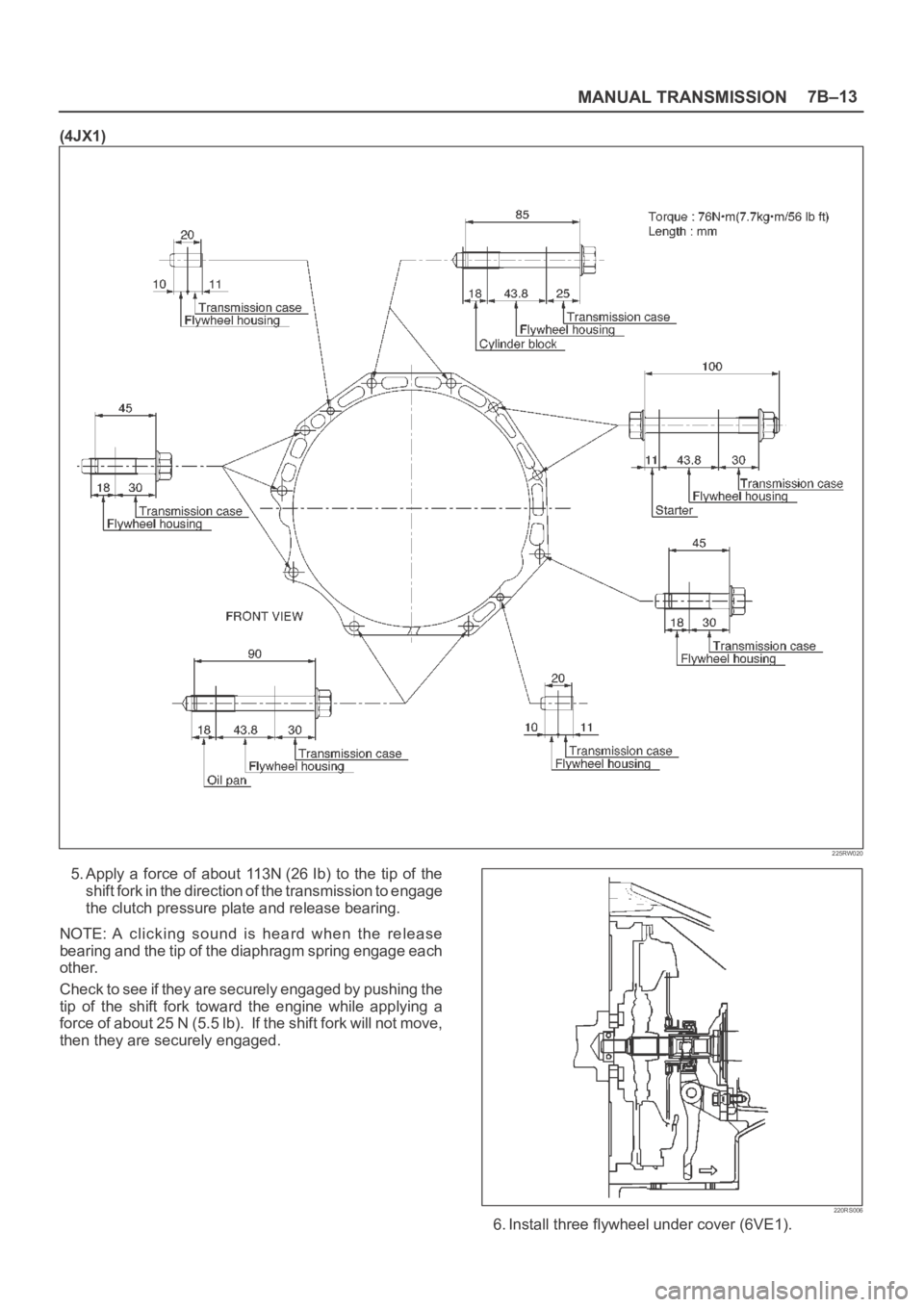
MANUAL TRANSMISSION7B–13
(4JX1)
225RW020
5. Apply a force of about 113N (26 Ib) to the tip of the
shift fork in the direction of the transmission to engage
the clutch pressure plate and release bearing.
NOTE: A clicking sound is heard when the release
bearing and the tip of the diaphragm spring engage each
other.
Check to see if they are securely engaged by pushing the
tip of the shift fork toward the engine while applying a
force of about 25 N (5.5 lb). If the shift fork will not move,
then they are securely engaged.
220RS006
6. Install three flywheel under cover (6VE1).
Page 2360 of 6000
7B–42MANUAL TRANSMISSION
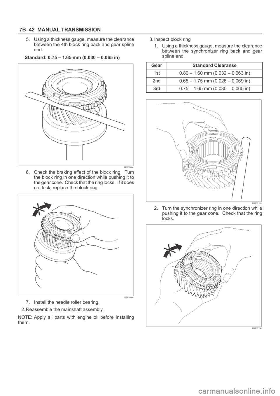
5. Using a thickness gauge, measure the clearance
between the 4th block ring back and gear spline
end.
Standard: 0.75 – 1.65 mm (0.030 – 0.065 in)
226RW064
6. Check the braking effect of the block ring. Turn
the block ring in one direction while pushing it to
the gear cone. Check that the ring locks. If it does
not lock, replace the block ring.
226RW060
7. Install the needle roller bearing.
2. Reassemble the mainshaft assembly.
NOTE: Apply all parts with engine oil before installing
them.3. Inspect block ring
1. Using a thickness gauge, measure the clearance
between the synchronizer ring back and gear
spline end.
Gear
Standard Clearanse
1st0.80–1.60mm (0.032–0.063in)
2nd0.65–1.75mm (0.026–0.069in)
3rd0.75–1.65mm (0.030–0.065in)
226RW105
2. Turn the synchronizer ring in one direction while
pushing it to the gear cone. Check that the ring
locks.
226RW106