direction OPEL FRONTERA 1998 Repair Manual
[x] Cancel search | Manufacturer: OPEL, Model Year: 1998, Model line: FRONTERA, Model: OPEL FRONTERA 1998Pages: 6000, PDF Size: 97 MB
Page 2363 of 6000

MANUAL TRANSMISSION7B–45
8. Install 3rd gear.
1. Install the 3rd gear needle bearing, 3rd gear and
3rd block ring to the mainshaft.
226RW098
9. Install the clutch hub No.2.
1. Install the clutch hub No.2 and hub sleeve No.2.
NOTE: Be careful the direction of the clutch hub No.2, as
shown.
2. Using a screwdriver, install 3 inserts and 2
springs.
NOTE: Position the insert springs so that their end gaps
are not in line.
226RW099
3. Using installer 5–8840–2553–0 (J–42797) and a
press, install the clutch nob No.2 and hub sleeve
No.2 to the mainshaft.NOTE:
Align the brock ring slots with the inserts.
Check that the gear rotates smoothly.
226RW206
4. Select a snap ring that will allow minimum axial
play.
Mark
Thickness
A1.80–1.85mm (0.071–0.073in)
B1.85–1.90mm (0.073–0.075in)
C1.90–1.95mm (0.075–0.077in)
D1.95–2.00mm (0.077–0.079in)
E2.00–2.05mm (0.079–0.081in)
F2.05–2.10mm (0.081–0.083in)
G2.10–2.15mm (0.083–0.085in)
226RW102
Page 2365 of 6000

MANUAL TRANSMISSION7B–47
11. Install the clutch hub No.1.
1. Install the 3 inserts and 3 insert springs to the
clutch hub No.1.
Reference: While pushing the insert spring
with a screwdriver, install the inserts.
226RW108
2. Install the clutch hub No.1 to the reverse gear.
NOTE: Check the clutch hub No.1 installing direction, as
shown.
226RW109
3. Using installer 5–8840–2554–0 (J–42798) and a
press, install the hub No.1 by retaining the
reverse gear.NOTE:
Align the projection of inner ring with hub No.1 slots.
Check that the gear rotates smoothly.
226RW205
4. Select a snap ring that will allow minimum axial
play.
Mark
Thickness
A2.30–2.35mm (0.091–0.093in)
B2.35–2.40mm (0.093–0.095in)
C2.40–2.45mm (0.095–0.097in)
D2.45–2.50mm (0.097–0.098in)
E2.50–2.55mm (0.098–0.100in)
F2.55–2.60mm (0.100–0.102in)
G2.60–2.65mm (0.102–0.104in)
226RW111
Page 2378 of 6000

7B–60MANUAL TRANSMISSION
2. Install the synchronizer outer ring, synchronizer
cone ring, and synchronizer pull ring to the
reverse block ring.
226RW121
3. Turn to 30 degree the reverse synchronizer pull
ring.
226RW080
4. Install the hub sleeve No.3 and reverse block ring
set to the counter 5th gear.
NOTE: Check the hub sleeve No.3 direction, as shown.
Reference: While pushing the 3 inserts,
install the synchronizer ring assembly to the
hub sleeve No.3.
226RW184
5. Slide the hub sleeve No.3.
226RW123
Page 2520 of 6000

CLUTCH7C–11
1. Use a straight edge and a feeler gauge to measure
the pressure plate friction surface flatness in four
directions.
2. If any of the measured values exceeds the specified
limit, the pressure plate must be replaced.
Pressure Plate Warpage
Limit: 0.3 mm (0.012 in)
Clutch Cover
201RS004
1. Visually check the entire clutch cover for excessive
wear, cracking, and other damage.
2. The clutch cover must be replaced if any of these
conditions are present.
Clutch Set Force
201RS005
1. Invert the pressure plate assembly.2. Place a new driven plate over the pressure plate. A
metal sheet with “A” thickness of 8.3 mm (0.327 in)
may be used in place of the driven plate.
3. Compress the pressure plate assembly until the
distance “B” becomes 12 mm (0.472 in).
4. Note the pressure gauge reading.
5. If the measured value is less than the specified limit,
the pressure plate assembly must be replaced.
Clutch Set Force
Standard: 7208 N ( 1621 lb)
Limit: 6468 N (1454 lb)
Diaphragm Spring Finger Height
201RW009
Legend
(1) Release Side
1. Place a new driven plate or a 8.3 mm (0.327 in)
spacer beneath the pressure plate.
2. Fully compress the pressure plate and diaphragm
spring.
3. There are two ways to do this.
4. Use a bench press to press down on the assembly
from the top.
5. Tighten the fixing bolts.
NOTE: Preload on diaphragm spring finger must be 49 –
98 N (11 – 22 lb) in direction of release, when clutch cover
assembly is bolted to the flywheel.
6. Measure the spring height from base to spring tip “A”.
If the measured value exceeds the specified limit, the
pressure plate assembly must be replaced.
Diaphragm Spring Finger Height
Standard: 49.9 mm – 51.9 mm (1.965 in –
2.043 in)
Page 2525 of 6000

7C–16CLUTCH
8. Apply molybdenum disulfide type grease to the areas
shown in illustration.
201RW012
9. Install the release bearing in the proper direction.
NOTE: Ensure release bearing is properly positioned
during installation, as shown in illustration.
201RW020
10. Install driven plate assembly. Use the pilot aligner
5-85253-001-0 (J-24547) to install the driven plate
assembly.
201RW027
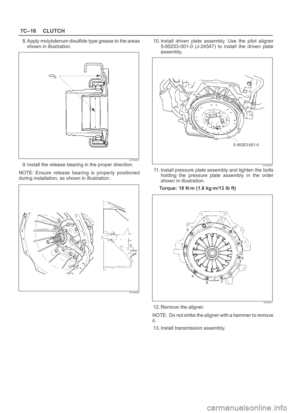
11. Install pressure plate assembly and tighten the bolts
holding the pressure plate assembly in the order
shown in illustration.
Torque: 18 Nꞏm (1.8 kgꞏm/13 lb ft)
201RS017
12. Remove the aligner.
NOTE: Do not strike the aligner with a hammer to remove
it.
13. Install transmission assembly.
Page 2550 of 6000

LIGHTING SYSTEM8A–11
Side Turn Signal Light Bulb
Removal
1. Disconnect the battery ground cable.
2. Pull the light/bulb(1) toward you while pushing the
light housing in the rear direction of the vehicle to
release its lock.
3. Remove the bulb by turning it counterclockwise while
pushing it at the same time.
801RW013
Installation
To install, follow the removal steps in the reverse order.
Rear Turn Signal Light Bulb
Removal
1. Disconnect the battery ground cable.
2. Remove the three screws and release the lock at two
positions.
3. Remove the rear combination light(3).
4. Remove the turn signal light socket/bulb(1) by turning
it counterclockwise.
5. Remove the bulb(2) by turning it counterclockwise
while pushing it at the same time.
803RS002
Installation
To install, follow the removal steps in the reverse order.
Page 2575 of 6000

8B–6WIPER/WASHER SYSTEM
Windshield Wiper Blade Rubber
Removal
1. Push the wiper blade lock(1) while pulling the wiper
blade in the arrow direction as shown in the figure.
CAUTION: W h e n t h e w i p e r b l a d e h a s b e e n
removed, wrap the tip of the wiper arm with cloth, to
avoid damaging the glass.
880RS011
2. Pull the end of rubber and remove the projection(3)
from the click of the blade stay (2).
880RS010
3. Pull the rubber out in the same direction.
Installation
To install, follow the removal steps in the reverse order,
noting the following points.
1. Install the click of the blade stay in the groove of the
new rubber and slide it in. Complete wiper blade
installation by pushing the click.
885RS002
2. Finally, check that the click of the stay has caught in
the hole of the rubber.
885RS001
Page 2599 of 6000

Waterproof Connector Inspection
It is not possible to insert the test probes (2) into the
connector wire side of a waterproof connector.
Use one side of a connector (1) with its wires cut to make
the test. Connect the test connector to the connector to
be tested (3). Connect the test probes to the cut wires to
check the connector continuity.
Connector Pin Removal – Connector
Housing Tang Lock Type
1. Insert a slender shaft (1) into the connector housing
open end (5).
2. Push the tang lock (2) up (in the direction of the arrow
in the illustration).
Pull the wire (3) with pin (4) free from the wire side of
the connector.
Connector Pin Removal – Pin Tang Lock
Ty p e
1. Insert a slender shaft (1) into the connector housing
open end (5).
2. Push the tang lock (2) flat (toward the wire (3) side of
the connector.
Pull the wire with pin (4) free from the wire side of the
connector.
Connector Pin Insertion
1. Check that the tang lock (1) is fully up.
2. Insert the pin (3) from the connector wire (2) side.
Push the pin in until the tang lock closes firmly.
3. Gently pull on the wires to make sure that the
connector pin is firmly set in place.
1
3
21
2
3
5
4
1
2
3
4 51
2
3
Page 2601 of 6000

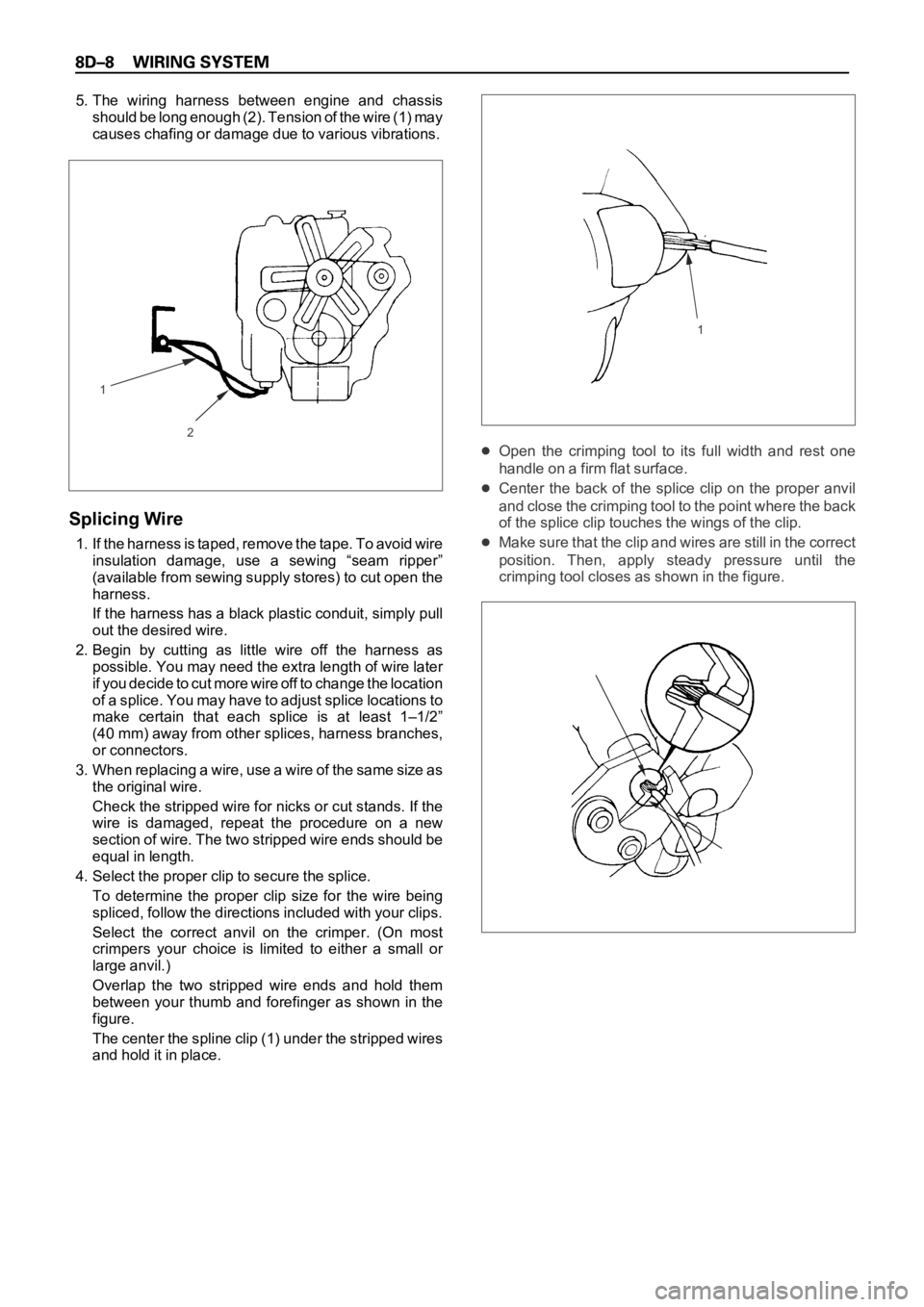
5. The wiring harness between engine and chassis
should be long enough (2). Tension of the wire (1) may
causes chafing or damage due to various vibrations.
Splicing Wire
1. If the harness is taped, remove the tape. To avoid wire
insulation damage, use a sewing “seam ripper”
(available from sewing supply stores) to cut open the
harness.
If the harness has a black plastic conduit, simply pull
out the desired wire.
2. Begin by cutting as little wire off the harness as
possible. You may need the extra length of wire later
if you decide to cut more wire off to change the location
of a splice. You may have to adjust splice locations to
make certain that each splice is at least 1–1/2”
(40 mm) away from other splices, harness branches,
or connectors.
3 . W h e n r e p l a c i n g a w i r e , u s e a w i r e o f t h e s a m e s i z e a s
the original wire.
Check the stripped wire for nicks or cut stands. If the
wire is damaged, repeat the procedure on a new
section of wire. The two stripped wire ends should be
equal in length.
4. Select the proper clip to secure the splice.
To determine the proper clip size for the wire being
spliced, follow the directions included with your clips.
Select the correct anvil on the crimper. (On most
crimpers your choice is limited to either a small or
large anvil.)
Overlap the two stripped wire ends and hold them
between your thumb and forefinger as shown in the
figure.
The center the spline clip (1) under the stripped wires
and hold it in place.
Open the crimping tool to its full width and rest one
handle on a firm flat surface.
Center the back of the splice clip on the proper anvil
and close the crimping tool to the point where the back
of the splice clip touches the wings of the clip.
Make sure that the clip and wires are still in the correct
position. Then, apply steady pressure until the
crimping tool closes as shown in the figure.
2
11
Page 2602 of 6000

Before crimping the ends of the clip (1), be sure that:
The wires extend beyond the clip in each direction.
No strands of wire are cut loose, and
No insulation is caught under the clip.
Crimp the splice again, once on each end.
Does not let the crimping tool (2) extend beyond the edge
of the clip or you may damage or nick the wires as shown
in the figure.
5. Apply 60/40 resin core solder to the opening in the
back of the clip as shown in the figure.
Follow the manufacturer’s instructions for the solder
equipment you are using.6. Center and roll the splicing tape.
The tape should cover the entire splice.
Roll on enough tape (1) to duplicate the thickness of
the insulation on the existing wires.
Does not flag the tape (2). Flagged tape may not
provide enough insulation, and the flagged ends will
tangle with the other wires in the harness as shown in
the figure.
If the wire does not belong in a conduit or other
harness covering, tape the wire again. use a winding
motion to cover the first piece of tape as shown in the
figure.
1
2
12