fuse chart OPEL FRONTERA 1998 Owner's Manual
[x] Cancel search | Manufacturer: OPEL, Model Year: 1998, Model line: FRONTERA, Model: OPEL FRONTERA 1998Pages: 6000, PDF Size: 97 MB
Page 3497 of 6000
RESTRAINT CONTROL SYSTEM 9J1–10
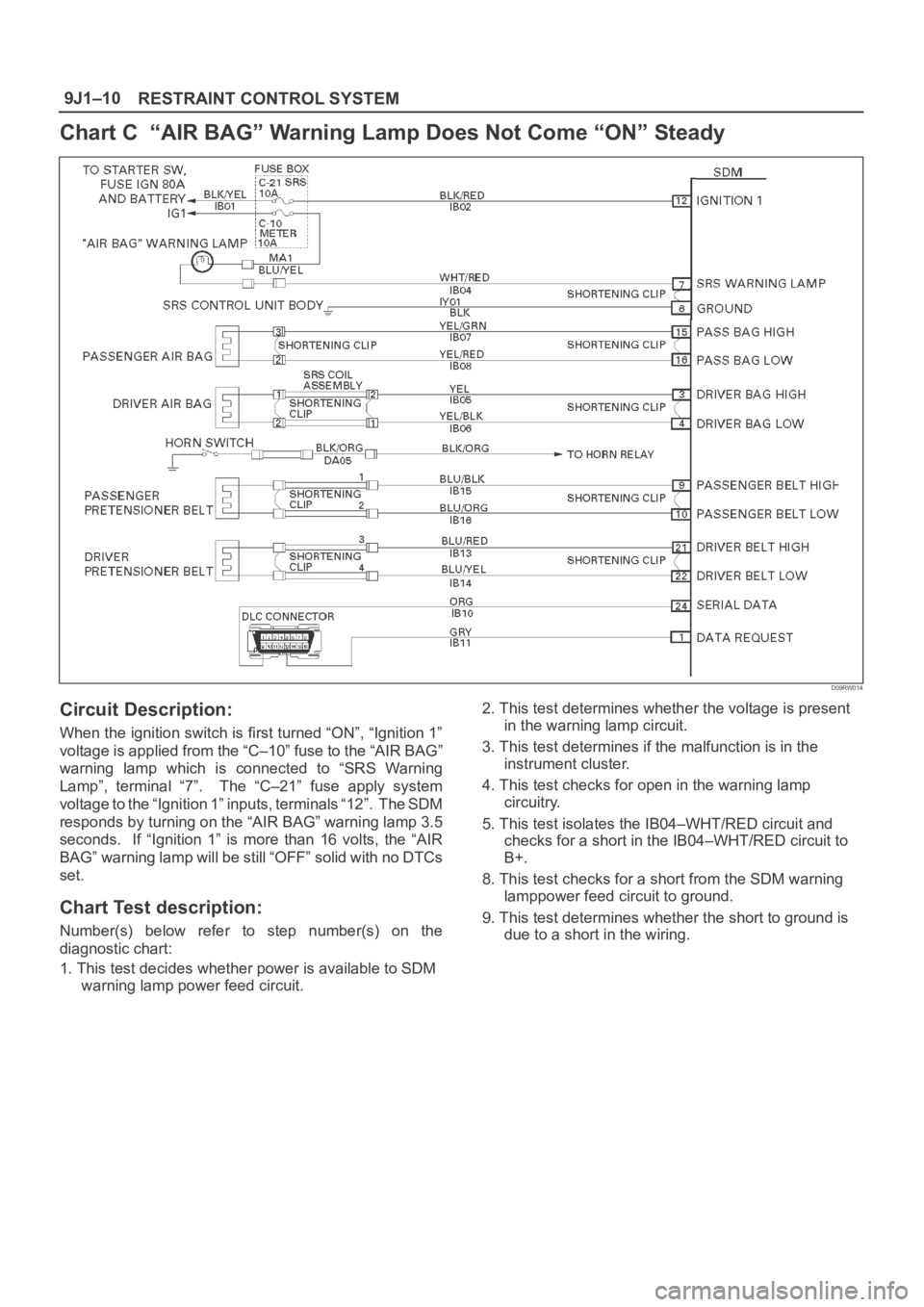
Chart C “AIR BAG” Warning Lamp Does Not Come “ON” Steady
D09RW014
Circuit Description:
When the ignition switch is first turned “ON”, “Ignition 1”
voltage is applied from the “C–10” fuse to the “AIR BAG”
warning lamp which is connected to “SRS Warning
Lamp”, terminal “7”. The “C–21” fuse apply system
voltage to the “Ignition 1” inputs, terminals “12”. The SDM
responds by turning on the “AIR BAG” warning lamp 3.5
seconds. If “Ignition 1” is more than 16 volts, the “AIR
BAG” warning lamp will be still “OFF” solid with no DTCs
set.
Chart Test description:
Number(s) below refer to step number(s) on the
diagnostic chart:
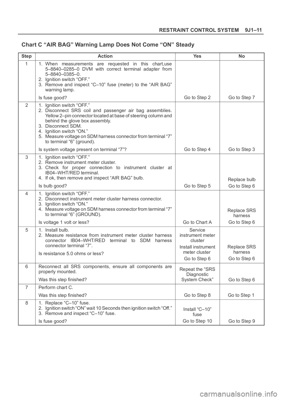
1. This test decides whether power is available to SDM
warning lamp power feed circuit.2. This test determines whether the voltage is present
in the warning lamp circuit.
3. This test determines if the malfunction is in the
instrument cluster.
4. This test checks for open in the warning lamp
circuitry.
5. This test isolates the IB04–WHT/RED circuit and
checks for a short in the IB04–WHT/RED circuit to
B+.
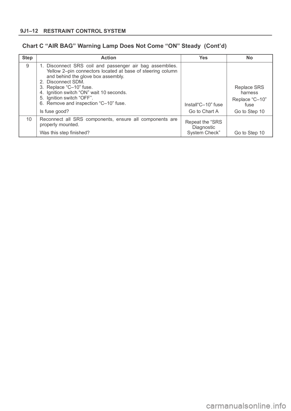
8. This test checks for a short from the SDM warning
lamppower feed circuit to ground.
9. This test determines whether the short to ground is
due to a short in the wiring.
Page 3498 of 6000
9J1–11
RESTRAINT CONTROL SYSTEM
Chart C “AIR BAG” Warning Lamp Does Not Come “ON” Steady
StepActionYe sNo
11. When measurements are requested in this chart,use
5–8840–0285–0 DVM with correct terminal adapter from
5–8840–0385–0.
2. Ignition switch “OFF.”
3. Remove and inspect “C–10” fuse (meter) to the “AIR BAG”
warning lamp.
Is fuse good?
Go to Step 2Go to Step 7
21. Ignition switch “OFF.”
2. Disconnect SRS coil and passenger air bag assemblies.
Yellow 2–pin connector located at base of steering column and
behind the glove box assembly.
3. Disconnect SDM.
4. Ignition switch “ON.”
5. Measure voltage on SDM harness connector from terminal “7”
to terminal “6” (ground).
Is system voltage present on terminal “7”?
Go to Step 4Go to Step 3
31. Ignition switch “OFF.”
2. Remove instrument meter cluster.
3. Check for proper connection to instrument cluster at
IB04–WHT/RED terminal.
4. If ok, then remove and inspect “AIR BAG” bulb.
Is bulb good?
Go to Step 5
Replace bulb
Go to Step 6
41. Ignition switch “OFF.”
2. Disconnect instrument meter cluster harness connector.
3. Ignition switch “ON.”
4. Measure voltage on SDM harness connector from terminal “7”
to terminal “6” (GROUND).
Is voltage 1 volt or less?
Go to Chart A
Replace SRS
harness
Go to Step 6
51. Install bulb.
2. Measure resistance from instrument meter cluster harness
connector IB04–WHT/RED terminal to SDM harness
connector terminal “7”.
Is resistance 5.0 ohms or less?Service
instrument meter
cluster
Install instrument
meter cluster
Go to Step 6
Replace SRS
harness
Go to Step 6
6Reconnect all SRS components, ensure all components are
properly mounted.
Was this step finished?Repeat the “SRS
Diagnostic
System Check”
Go to Step 6
7Perform chart C.
Was this step finished?
Go to Step 8Go to Step 1
81. Replace “C–10” fuse.
2. Ignition switch “ON” wait 10 Seconds then ignition switch “Off.”
3. Remove and inspect “C–10” fuse.
Is fuse good?
Install “C–10”
fuse
Go to Step 10
Go to Step 9
Page 3499 of 6000
RESTRAINT CONTROL SYSTEM 9J1–12
Chart C “AIR BAG” Warning Lamp Does Not Come “ON” Steady (Cont’d)
StepNo Ye s Action
91. Disconnect SRS coil and passenger air bag assemblies.
Yellow 2–pin connectors located at base of steering column
and behind the glove box assembly.
2. Disconnect SDM.
3. Replace “C–10” fuse.
4. Ignition switch “ON” wait 10 seconds.
5. Ignition switch “OFF”.
6. Remove and inspection “C–10” fuse.
Is fuse good?
Install“C–10” fuse
Go to Chart A
Replace SRS
harness
Replace “C–10”
fuse
Go to Step 10
10Reconnect all SRS components, ensure all components are
properly mounted.
Was this step finished?Repeat the “SRS
Diagnostic
System Check”
Go to Step 10
Page 4355 of 6000
5A–5 BRAKE CONTROL SYSTEM
FR
Front Right
GEN
Generator
MV
Millivolts
RL
Rear Left
RR
Rear RightRPS
Revolution per Second
VDC
Vo l t s D C
VA C
Vo l t s A C
W/L
Warning Light
WSS
Wheel Speed Sensor
General Diagnosis
General Information
ABS malfunction can be classified into two types, those
which can be detected by the ABS warning light and those
which can be detected as a vehicle abnormality by the
driver.
In either case, locate the fault in accordance with the
“BASIC DIAGNOSTIC FLOWCHART” and repair.
Please refer to Section 5C for the diagnosis of
mechanical troubles such as brake noise, brake judder
(brake pedal or vehicle vibration felt when braking),
uneven braking, and parking brake trouble.
ABS Service Precautions
Required Tools and Items:
Box Wrench
Brake Fluid
Special Tool
Some diagnosis procedures in this section require the
installation of a special tool.
J-39200 High Impedance Multimeter
When circuit measurements are requested, use a circuit
tester with high impedance.
Computer System Service Precautions
The Anti-lock Brake System interfaces directly with the
Electronic Hydraulic Control Unit (EHCU) which is a
control computer that is similar in some regards to the
Powertrain Control Module. These modules are designed
to withstand normal current draws associated with
vehicle operation. However, care must be taken to avoid
overloading any of the EHCU circuits. In testing for opens
or shorts, do not ground or apply voltage to any of the
circuits unless instructed to do so by the appropriate
diagnostic procedure. These circuits should only be
tested with a high impedance multimeter (J-39200) or
special tools as described in this section. Power should
never be removed or applied to any control module with
the ignition in the “ON” position.
Before removing or connecting battery cables, fuses or
connectors, always turn the ignition switch to the “OFF”
position.
General Service Precautions
The following are general precautions which should be
observed when servicing and diagnosing the Anti-lock
Brake System and/or other vehicle systems. Failure toobserve these precautions may result in Anti-lock Brake
System damage.
If welding work is to be performed on the vehicle using
an electric arc welder, the EHCU and valve block
connectors should be disconnected before the
welding operation begins.
The EHCU and valve block connectors should never
be connected or disconnected with the ignition “ON” .
EHCU of the Anti-lock Brake System are not
separately serviceable and must be replaced as
assemblies. Do not disassemble any component
which is designated as non-serviceable in this
Section.
If only rear wheels are rotated using jacks or drum
tester, the system will diagnose a speed sensor
malfunction and the “ABS” warning light will
illuminate. But actually no trouble exists. After
inspection stop the engine once and re-start it, then
make sure that the “ABS” warning light does not
illuminate.
If the battery has been discharged
The engine may stall if the battery has been completely
discharged and the engine is started via jumper cables.
This is because the Anti-lock Brake System (ABS)
requires a large quantity of electricity. In this case, wait
until the battery is recharged, or set the ABS to a
non-operative state by removing the fuse for the ABS
(40A). After the battery has been recharged, stop the
engine and install the ABS fuse. Start the engine again,
and confirm that the ABS warning light does not light.
Note on Intermittents
As with virtually any electronic system, it is difficult to
identify an intermittent failure. In such a case duplicating
the system malfunction during a test drive or a good
description of vehicle behavior from the customer may be
helpful in locating a “most likely” failed component or
circuit. The symptom diagnosis chart may also be useful
in isolating the failure. Most intermittent problems are
caused by faulty electrical connections or wiring. When
an intermittent failure is encountered, check suspect
circuits for:
Suspected harness damage.
Poor mating of connector halves or terminals not fully
seated in the connector body (backed out).
Improperly formed or damaged terminals.
Page 4387 of 6000
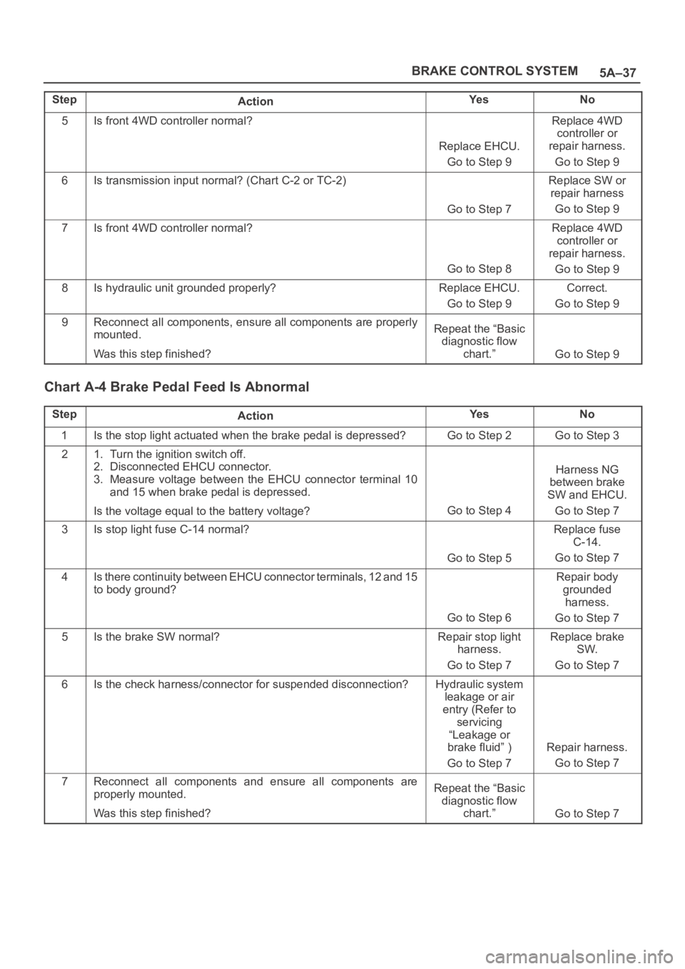
5A–37 BRAKE CONTROL SYSTEM
StepNo Ye s
Action
5Is front 4WD controller normal?
Replace EHCU.
Go to Step 9
Replace 4WD
controller or
repair harness.
Go to Step 9
6Is transmission input normal? (Chart C-2 or TC-2)
Go to Step 7
Replace SW or
repair harness
Go to Step 9
7Is front 4WD controller normal?
Go to Step 8
Replace 4WD
controller or
repair harness.
Go to Step 9
8Is hydraulic unit grounded properly?Replace EHCU.
Go to Step 9Correct.
Go to Step 9
9Reconnect all components, ensure all components are properly
mounted.
Was this step finished?Repeat the “Basic
diagnostic flow
chart.”
Go to Step 9
Chart A-4 Brake Pedal Feed Is Abnormal
StepActionYe sNo
1Is the stop light actuated when the brake pedal is depressed?Go to Step 2Go to Step 3
21. Turn the ignition switch off.
2. Disconnected EHCU connector.
3. Measure voltage between the EHCU connector terminal 10
and 15 when brake pedal is depressed.
Is the voltage equal to the battery voltage?
Go to Step 4
Harness NG
between brake
SW and EHCU.
Go to Step 7
3Is stop light fuse C-14 normal?
Go to Step 5
Replace fuse
C-14.
Go to Step 7
4Is there continuity between EHCU connector terminals, 12 and 15
to body ground?
Go to Step 6
Repair body
grounded
harness.
Go to Step 7
5Is the brake SW normal?Repair stop light
harness.
Go to Step 7Replace brake
SW.
Go to Step 7
6Is the check harness/connector for suspended disconnection?Hydraulic system
leakage or air
entry (Refer to
servicing
“Leakage or
brake fluid” )
Go to Step 7
Repair harness.
Go to Step 7
7Reconnect all components and ensure all components are
properly mounted.
Was this step finished?Repeat the “Basic
diagnostic flow
chart.”
Go to Step 7
Page 4393 of 6000
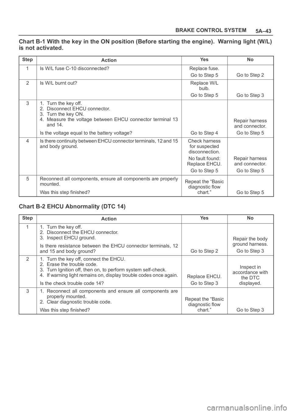
5A–43 BRAKE CONTROL SYSTEM
Chart B-1 With the key in the ON position (Before starting the engine). Warning light (W/L)
is not activated.
StepActionYe sNo
1Is W/L fuse C-10 disconnected?Replace fuse.
Go to Step 5
Go to Step 2
2Is W/L burnt out?Replace W/L
bulb.
Go to Step 5
Go to Step 3
31. Turn the key off.
2. Disconnect EHCU connector.
3. Turn the key ON.
4. Measure the voltage between EHCU connector terminal 13
and 14.
Is the voltage equal to the battery voltage?
Go to Step 4
Repair harness
and connector.
Go to Step 5
4Is there continuity between EHCU connector terminals, 12 and 15
and body ground.Check harness
for suspected
disconnection.
No fault found:
Replace EHCU.
Go to Step 5
Repair harness
and connector.
Go to Step 5
5Reconnect all components, ensure all components are properly
mounted.
Was this step finished?Repeat the “Basic
diagnostic flow
chart.”
Go to Step 5
Chart B-2 EHCU Abnormality (DTC 14)
StepActionYe sNo
11. Turn the key off.
2. Disconnect the EHCU connector.
3. Inspect EHCU ground.
Is there resistance between the EHCU connector terminals, 12
and 15 and body ground?
Go to Step 2
Repair the body
ground harness.
Go to Step 3
21. Turn the key off, connect the EHCU.
2. Erase the trouble code.
3. Turn Ignition off, then on, to perform system self-check.
4. If warning light remains on, display trouble codes once again.
Is the check trouble code 14?
Replace EHCU.
Go to Step 3
Inspect in
accordance with
the DTC
displayed.
31. Reconnect all components and ensure all components are
properly mounted.
2. Clear diagnostic trouble code.
Was this step finished?
Repeat the “Basic
diagnostic flow
chart.”
Go to Step 3
Page 4397 of 6000
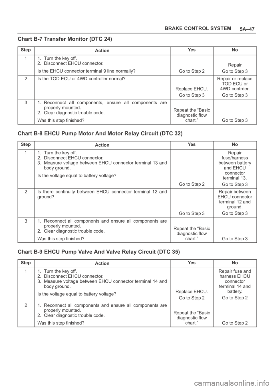
5A–47 BRAKE CONTROL SYSTEM
Chart B-7 Transfer Monitor (DTC 24)
StepActionYe sNo
11. Turn the key off.
2. Disconnect EHCU connector.
Is the EHCU connector terminal 9 line normally?
Go to Step 2
Repair
Go to Step 3
2Is the TOD ECU or 4WD controller normal?
Replace EHCU.
Go to Step 3
Repair or replace
TOD ECU or
4WD contrder.
Go to Step 3
31. Reconnect all components, ensure all components are
properly mounted.
2. Clear diagnostic trouble code.
Was this step finished?
Repeat the “Basic
diagnostic flow
chart.”
Go to Step 3
Chart B-8 EHCU Pump Motor And Motor Relay Circuit (DTC 32)
StepActionYe sNo
11. Turn the key off.
2. Disconnect EHCU connector.
3. Measure voltage between EHCU connector terminal 13 and
body ground.
Is the voltage equal to battery voltage?
Go to Step 2
Repair
fuse/harness
between battery
and EHCU
connector
terminal 13.
Go to Step 3
2Is there continuity between EHCU connector terminal 12 and
ground?
Go to Step 3
Repair between
EHCU connector
terminal 12 and
ground.
Go to Step 3
31. Reconnect all components and ensure all components are
properly mounted.
2. Clear diagnostic trouble code.
Was this step finished?
Repeat the “Basic
diagnostic flow
chart.”
Go to Step 3
Chart B-9 EHCU Pump Valve And Valve Relay Circuit (DTC 35)
StepActionYe sNo
11. Turn the key off.
2. Disconnect EHCU connector.
3. Measure voltage between EHCU connector terminal 14 and
body ground.
Is the voltage equal to battery voltage?
Replace EHCU.
Go to Step 2
Repair fuse and
harness EHCU
connector
terminal 14 and
battery.
Go to Step 2
21. Reconnect all components and ensure all components are
properly mounted.
2. Clear diagnostic trouble code.
Was this step finished?
Repeat the “Basic
diagnostic flow
chart.”
Go to Step 2
Page 4731 of 6000
6E–74
ENGINE DRIVEABILITY AND EMISSIONS
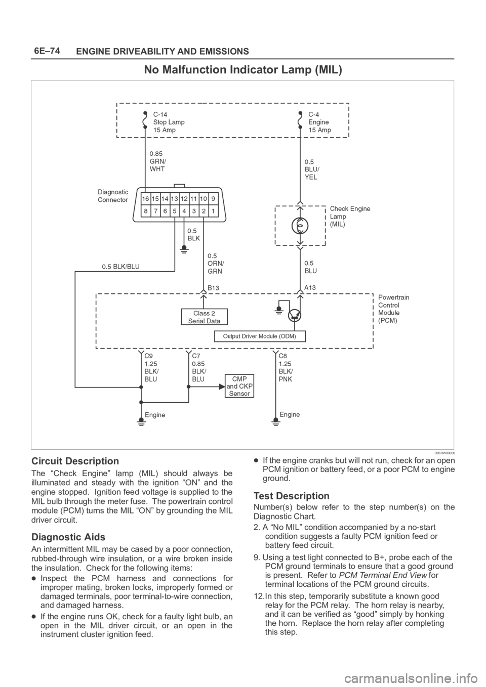
No Malfunction Indicator Lamp (MIL)
D06RW00006
Circuit Description
The “Check Engine” lamp (MIL) should always be
illuminated and steady with the ignition “ON” and the
engine stopped. Ignition feed voltage is supplied to the
MIL bulb through the meter fuse. The powertrain control
module (PCM) turns the MIL “ON” by grounding the MIL
driver circuit.
Diagnostic Aids
An intermittent MIL may be cased by a poor connection,
rubbed-through wire insulation, or a wire broken inside
the insulation. Check for the following items:
Inspect the PCM harness and connections for
improper mating, broken locks, improperly formed or
damaged terminals, poor terminal-to-wire connection,
and damaged harness.
If the engine runs OK, check for a faulty light bulb, an
open in the MIL driver circuit, or an open in the
instrument cluster ignition feed.
If the engine cranks but will not run, check for an open
PCM ignition or battery feed, or a poor PCM to engine
ground.
Test Description
Number(s) below refer to the step number(s) on the
Diagnostic Chart.
2. A “No MIL” condition accompanied by a no-start
condition suggests a faulty PCM ignition feed or
battery feed circuit.
9. Using a test light connected to B+, probe each of the
PCM ground terminals to ensure that a good ground
is present. Refer to
PCM Terminal End View for
terminal locations of the PCM ground circuits.
12.In this step, temporarily substitute a known good
relay for the PCM relay. The horn relay is nearby,
and it can be verified as “good” simply by honking
the horn. Replace the horn relay after completing
this step.
Page 4891 of 6000
6E–234
ENGINE DRIVEABILITY AND EMISSIONS
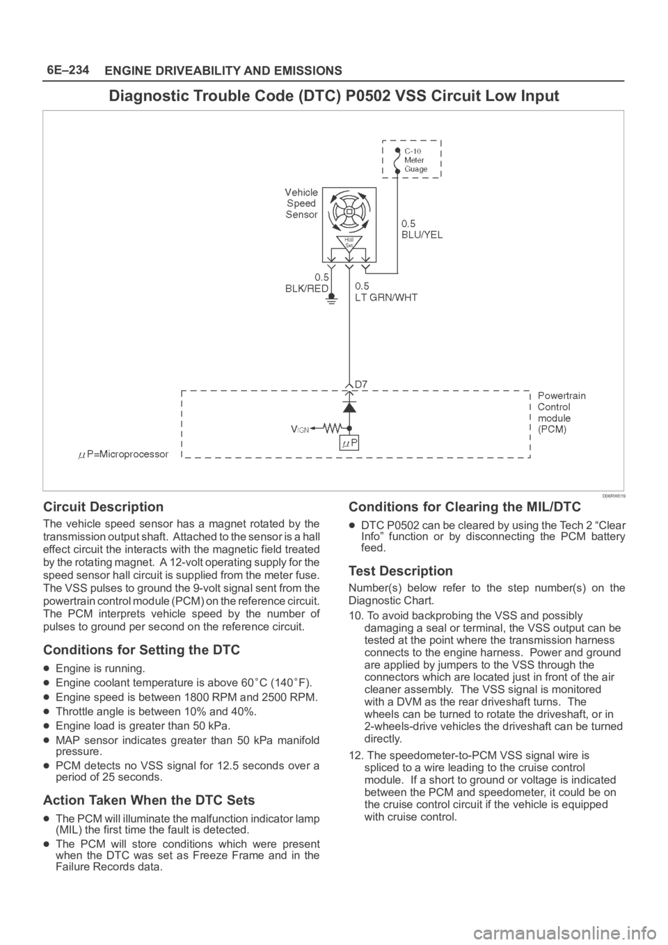
Diagnostic Trouble Code (DTC) P0502 VSS Circuit Low Input
D06RW019
Circuit Description
The vehicle speed sensor has a magnet rotated by the
transmission output shaft. Attached to the sensor is a hall
effect circuit the interacts with the magnetic field treated
by the rotating magnet. A 12-volt operating supply for the
speed sensor hall circuit is supplied from the meter fuse.
The VSS pulses to ground the 9-volt signal sent from the
powertrain control module (PCM) on the reference circuit.
The PCM interprets vehicle speed by the number of
pulses to ground per second on the reference circuit.
Conditions for Setting the DTC
Engine is running.
Engine coolant temperature is above 60C (140F).
Engine speed is between 1800 RPM and 2500 RPM.
Throttle angle is between 10% and 40%.
Engine load is greater than 50 kPa.
MAP sensor indicates greater than 50 kPa manifold
pressure.
PCM detects no VSS signal for 12.5 seconds over a
period of 25 seconds.
Action Taken When the DTC Sets
The PCM will illuminate the malfunction indicator lamp
(MIL) the first time the fault is detected.
The PCM will store conditions which were present
when the DTC was set as Freeze Frame and in the
Failure Records data.
Conditions for Clearing the MIL/DTC
DTC P0502 can be cleared by using the Tech 2 “Clear
Info” function or by disconnecting the PCM battery
feed.
Test Description
Number(s) below refer to the step number(s) on the
Diagnostic Chart.
10. To avoid backprobing the VSS and possibly
damaging a seal or terminal, the VSS output can be
tested at the point where the transmission harness
connects to the engine harness. Power and ground
are applied by jumpers to the VSS through the
connectors which are located just in front of the air
cleaner assembly. The VSS signal is monitored
with a DVM as the rear driveshaft turns. The
wheels can be turned to rotate the driveshaft, or in
2-wheels-drive vehicles the driveshaft can be turned
directly.
12. The speedometer-to-PCM VSS signal wire is
spliced to a wire leading to the cruise control
module. If a short to ground or voltage is indicated
between the PCM and speedometer, it could be on
the cruise control circuit if the vehicle is equipped
with cruise control.
Page 4916 of 6000
6E–259 ENGINE DRIVEABILITY AND EMISSIONS
Diagnostic Trouble Code (DTC) P1640 Driver-1-Input High Voltage
Circuit Description
Output driver modules (ODMs) are used by the
powertrain control module (PCM) to turn “ON” many of
the current-driven devices that are needed to control
various engine and transmission functions. Each ODM is
capable of controlling up to 7 separate outputs by
applying ground to the device which the PCM is
commanding “ON.”
Unlike the Quad Driver Modules (QDMs) used in prior
model years, ODMs have the capability of diagnosing
each output circuit individually. DTC P1640 set indicates
an improper voltage level has been detected on an ODM
output.
Since A/C is an option, No A/C will cause the air
conditioning clutch relay output to always fault. If a fault is
seen on the air conditioning clutch relay output, it will not
be logged as a fault until the A/C request input interrupts a
high voltage, indicating that A/C has been installed.
Conditions for Setting the DTC
Ignition “ON.”
Engine running.
No DTC 1618.
Ignition voltage is above 13.2 volts for 4 seconds.
Output voltage does not equal ignition voltage when
output is “OFF” or output voltage is not less than 1 volt
when output is “ON.”
Above conditions occur for at least 1 second.
Action Taken When the DTC Sets
The PCM will not illuminate the malfunction indicator
lamp (MIL).
The PCM will store conditions which were present
when the DTC was set as Failure Records only. This
information will not be stored as Freeze Frame data.
Conditions for Clearing the MIL/DTC
DTC P1640 can be cleared by using the Tech 2 “Clear
Info” function or by disconnecting the PCM battery
feed.
Diagnostic Aids
Check for the following conditions:
Poor connection at PCM – Inspect harness connectors
for backed-out terminals, improper mating, broken
locks, improperly formed or damaged terminals, and
poor terminal-to-wire connection.
Damaged harness – Inspect the wiring harness for
damage, If the harness appears to be OK, disconnect
the PCM, turn the ignition “ON” and observe a
voltmeter connected to the suspect driver circuit at the
PCM harness connector while moving connectors and
wiring harnesses relates to the MIL. A change in
voltage will indicate the location of the fault.
Poor connection at component – Examine for
damaged connectors, unplugged connector, or
damaged terminals at the following locations:
Instrument cluster harness, canister purge solenoid,
A/C clutch relay. An open ignition feed circuit at any of
these components will cause DTC P1640 to be set.
Reviewing the Failure Records vehicle mileage since the
diagnostic test last failed may help determine how often
the condition that caused the DTC to be set occurs. This
may assist in diagnosing the condition.
The following PCM pins are controlled by output driver
modules (ODMs):
A13 – “Check Engine Lamp”
A14 – SVS (”Check Trans”)
B14 – A/C Clutch
Test Description
Number(s) below refer to the step number(s) on the
Diagnostic Chart.
6. The Tech 2 Driver Module Status indicates the PCM
pin that is affected.
11. The Tech 2 may indicate “short circuit” even when
the problem is an open circuit. The cause of an
open circuit may be in the component itself-lamp,
purge, solenoid, or A/C compressor relay.
13.A short to ground on the ignition side of the
component will blow the fuse. Since the fuse was
checked in Step 4, a short to ground would be
between the affected component and the PCM.