sensor OPEL FRONTERA 1998 Owner's Manual
[x] Cancel search | Manufacturer: OPEL, Model Year: 1998, Model line: FRONTERA, Model: OPEL FRONTERA 1998Pages: 6000, PDF Size: 97 MB
Page 472 of 6000

DIFFERENTIAL (REAR 220mm)
4A2A–5
8. Disconnect the ABS connectors (1) and remove the
brackets (2) attached to the frame and center link
(ABS model only).
350RS001
9. Loosen the brake tube flare nut, remove the clip and
take out the brake tube.
10. Remove the shock absorber fixing nut from the axle
housing.
11. Remove the stabilizer linkage mounting nut from the
axle housing.
12. Remove the lateral rod fixing nut from the axle
housing.
13. Remove the center link mounting bolt and nut from
the axle housing.
14. Remove the trailing link fixing bolt and nut from the
axle housing.
15. Jack down and remove the coil spring and insulator.
16. Axle housing assembly can be separated from the
vehicle on completion of steps 1 – 11.
17. Remove the brake caliper fixing bolt (3), loosen the
flare nut (1), release the clip (2) and take out the brake
caliper together with the flexible hose.
306RS001
18. Remove brake disc.
19. Remove antilock brake system speed sensor fixing
bolt and the clip and bracket on the axle housing
(ABS model only).
20. Remove the brake pipe clip and fixing bolt on the axle
housing and take out the brake pipe.
21. Remove the bearing holder fixing nut and take out the
axle shaft assembly, be sure not to damage the oil
seal by the spline of the shaft, Refer to Axle Shaft in
this section.
22. Remove differential assembly, refer to Differential
Assembly in this section.
Oil Seal Replacement
Remove the oil seal, carefully not to damage the housing,
and mount new oil seal using oil seal installer
5–8840–2294–0.
420RW028
Installation
1. Install differential assembly, refer to Differential
Assembly in this section.
2. Install axle shaft assembly then tighten the bearing
holder mounting nut to the specified torque. Be sure
not to damage the oil seal by the spline of the shaft.
Torque: 74Nꞏm (7.5kgꞏm/54lb ft)
3. Install brake pipe.
4. Connect antilock brake system (ABS) speed sensor
and harness, refer to 4–Wheel Anti–Lock Brake
System (ABS) in Brake section (ABS model only).
5. Install brake disc.
6. Install brake caliper. Refer to Disk Brakes in Brake
section.
7. Install axle housing assembly.
8. Install coil spring and insulator.
9. Install the trailing link fixing bolt and nut to the axle
housing. For the procedures in items 9–13, refer to
Suspension section.
10. Install the center link bolt and nut to the axle housing.
Page 475 of 6000

4A2A–8
DIFFERENTIAL (REAR 220mm)
Differential Assembly
Differential Assembly and Associated Parts
425RW055
Legend
(1) Bolt and Nut
(2) Axle Shaft Assembly(3) Parking Brake Cable
(4) Differential Assembly
(5) Nut
Removal
1. Jack up and support the frame with stands.
2. Remove the wheel and tire. Refer to Wheel in
Steering section.
3. Drain the differential oil.
4. Remove the propeller shaft. Refer to Rear Propeller
Shaft in this section.
5. Remove the ABS speed sensor(ABS model only).
Refer to 4–Wheel Anti–lock Brake System (ABS) in
Brake section.6. Remove the parking brake cable fastening clip and
disconnect the equalizer section. Refer to Parking
Brakes in Brake section.
7. Remove the bearing holder fixing nuts.
8. Remove axle shaft assembly, be sure not to damage
the oil seal by axle shaft.
9. Remove differential carrier mounting bolts and nuts.
10. Remove differential assembly.
Page 507 of 6000

4A2B–4DIFFERENTIAL (REAR 244mm)
Axle Housing
Axle Housing and Associated Parts
420RW001
Legend
(1) Coil Spring and Insulator
(2) Axle Housing Assembly
(3) ABS Speed Sensor and Harness (if so
equipped)
(4) Nut
(5) Parking Brake Cable
(6) Bolt and Nut
(7) Antilock Brake System (ABS) Connector and
Bracket (if so equipped)(8) Bolt and Nut
(9) Nut
(10) Differential Assembly
(11) Axle Shaft Assembly
(12) Brake Disc
(13) Brake Pipe
(14) Brake Caliper
(15) Nut
(16) Breather Hose
(17) Flare Nut
Removal
1. Raise the vehicle and support it with suitable safety
stands.
The hoist must remain under the rear axle housing.
2. Drain brake fluid. Refer to Hydraulic Brakes in Brakes
section.
3. Remove rear wheels and tires. Refer to Wheel in
Suspension section.4. Remove propeller shaft. Refer to Rear Propeller
Shaft in this section.
5. Drain the rear axle oil into a proper container.
6. Remove parking brake cable, release the connection
between the cable fixing clip equalizer. Refer to
Parking Brakes in Brakes section.
7. Move the clip aside and pull out the breather hose.
Page 508 of 6000
DIFFERENTIAL (REAR 244mm)
4A2B–5
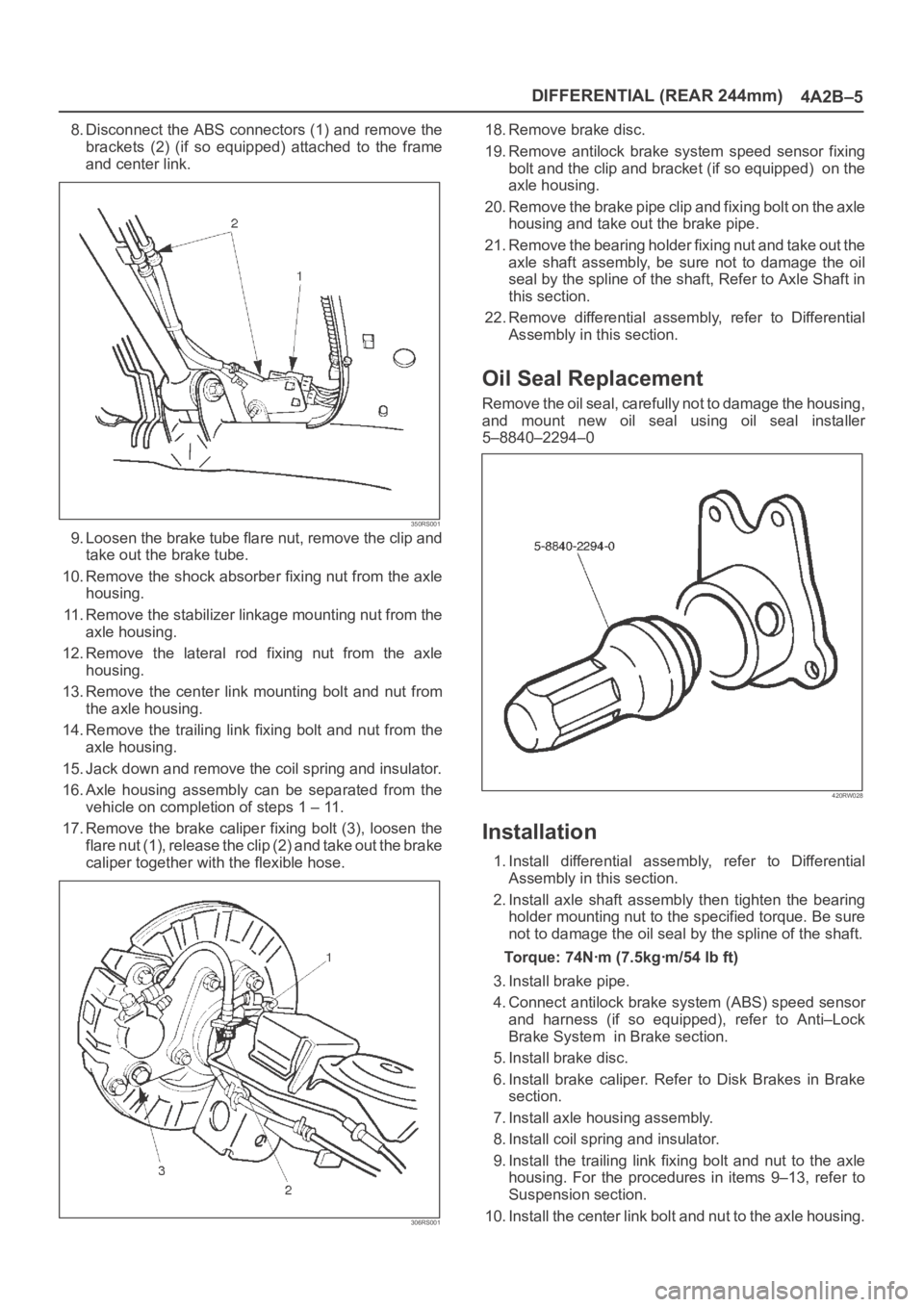
8. Disconnect the ABS connectors (1) and remove the
brackets (2) (if so equipped) attached to the frame
and center link.
350RS001
9. Loosen the brake tube flare nut, remove the clip and
take out the brake tube.
10. Remove the shock absorber fixing nut from the axle
housing.
11. Remove the stabilizer linkage mounting nut from the
axle housing.
12. Remove the lateral rod fixing nut from the axle
housing.
13. Remove the center link mounting bolt and nut from
the axle housing.
14. Remove the trailing link fixing bolt and nut from the
axle housing.
15. Jack down and remove the coil spring and insulator.
16. Axle housing assembly can be separated from the
vehicle on completion of steps 1 – 11.
17. Remove the brake caliper fixing bolt (3), loosen the
flare nut (1), release the clip (2) and take out the brake
caliper together with the flexible hose.
306RS001
18. Remove brake disc.
19. Remove antilock brake system speed sensor fixing
bolt and the clip and bracket (if so equipped) on the
axle housing.
20. Remove the brake pipe clip and fixing bolt on the axle
housing and take out the brake pipe.
21. Remove the bearing holder fixing nut and take out the
axle shaft assembly, be sure not to damage the oil
seal by the spline of the shaft, Refer to Axle Shaft in
this section.
22. Remove differential assembly, refer to Differential
Assembly in this section.
Oil Seal Replacement
Remove the oil seal, carefully not to damage the housing,
and mount new oil seal using oil seal installer
5–8840–2294–0
420RW028
Installation
1. Install differential assembly, refer to Differential
Assembly in this section.
2. Install axle shaft assembly then tighten the bearing
holder mounting nut to the specified torque. Be sure
not to damage the oil seal by the spline of the shaft.
Torque: 74Nꞏm (7.5kgꞏm/54 lb ft)
3. Install brake pipe.
4. Connect antilock brake system (ABS) speed sensor
and harness (if so equipped), refer to Anti–Lock
Brake System in Brake section.
5. Install brake disc.
6. Install brake caliper. Refer to Disk Brakes in Brake
section.
7. Install axle housing assembly.
8. Install coil spring and insulator.
9. Install the trailing link fixing bolt and nut to the axle
housing. For the procedures in items 9–13, refer to
Suspension section.
10. Install the center link bolt and nut to the axle housing.
Page 511 of 6000

4A2B–8DIFFERENTIAL (REAR 244mm)
Differential Assembly
Differential Assembly and Associated Parts
425RW044
Legend
(1) Bolt and Nut
(2) Axle Shaft Assembly(3) Parking Brake Cable
(4) Differential Assembly
(5) Nut
Removal
1. Jack up and support the frame with stands.
2. Remove the wheel and tire. Refer to Wheel in
Steering section.
3. Drain the differential oil.
4. Remove the propeller shaft. Refer to Rear Propeller
Shaft in this section.
5. Remove the ABS speed sensor. Refer to Anti–lock
Brake System in Brakes section.6. Remove the parking brake cable fastening clip and
disconnect the equalizer section. Refer to Parking
Brakes in Brake section.
7. Remove the bearing holder fixing nuts.
8. Remove axle shaft assembly, be sure not to damage
the oil seal by axle shaft.
9. Remove differential carrier mounting bolts and nuts.
10. Remove differential assembly.
Page 573 of 6000
DRIVE LINE CONTROL SYSTEM (TOD) 4B2–2
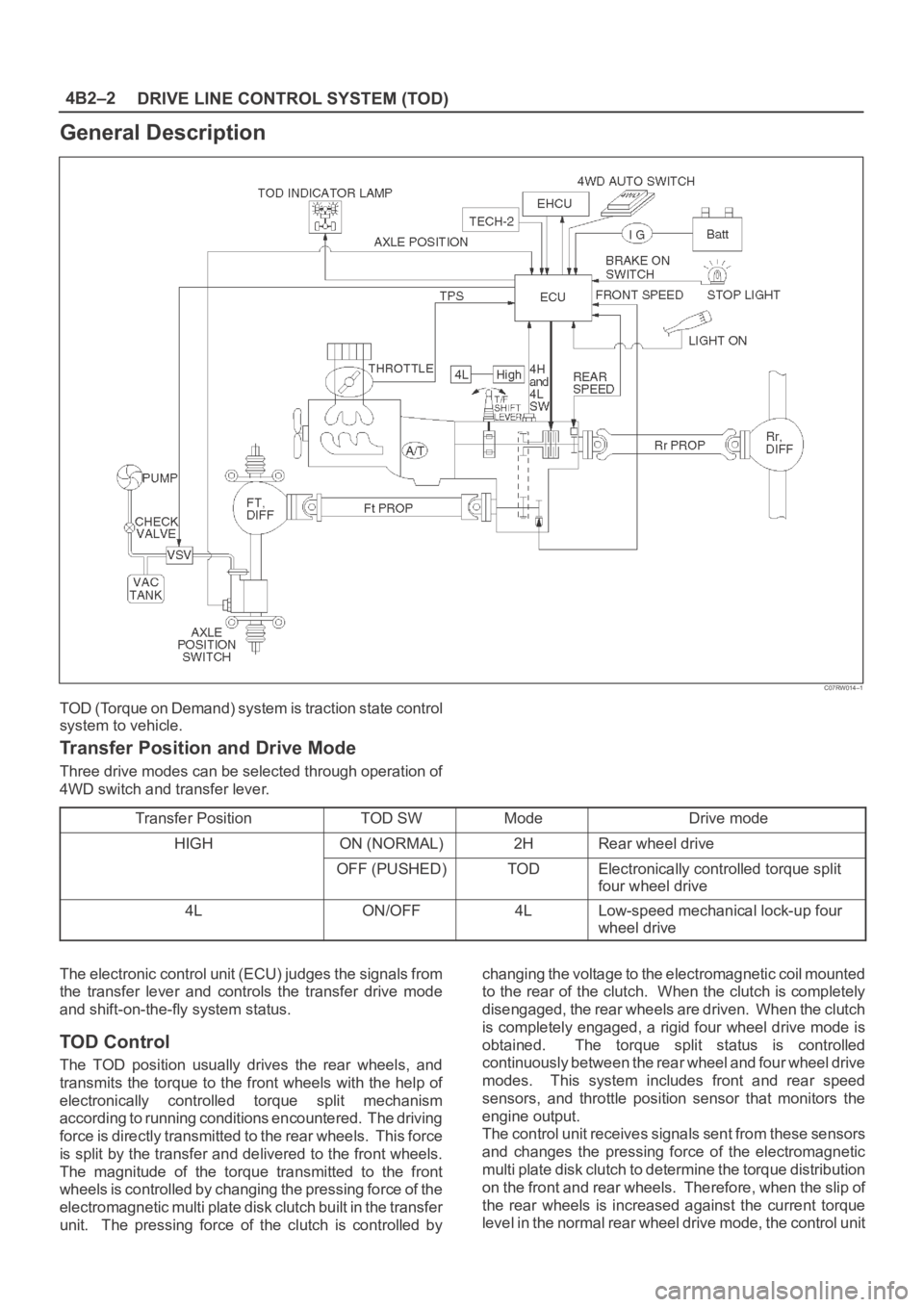
General Description
C07RW014–1
TOD (Torque on Demand) system is traction state control
system to vehicle.
Transfer Position and Drive Mode
Three drive modes can be selected through operation of
4WD switch and transfer lever.
Transfer Position
TOD SWModeDrive mode
HIGHON (NORMAL)2HRear wheel drive
OFF (PUSHED)TODElectronically controlled torque split
four wheel drive
4LON/OFF4LLow-speed mechanical lock-up four
wheel drive
The electronic control unit (ECU) judges the signals from
the transfer lever and controls the transfer drive mode
and shift-on-the-fly system status.
TOD Control
The TOD position usually drives the rear wheels, and
transmits the torque to the front wheels with the help of
electronically controlled torque split mechanism
according to running conditions encountered. The driving
force is directly transmitted to the rear wheels. This force
is split by the transfer and delivered to the front wheels.
The magnitude of the torque transmitted to the front
wheels is controlled by changing the pressing force of the
electromagnetic multi plate disk clutch built in the transfer
unit. The pressing force of the clutch is controlled bychanging the voltage to the electromagnetic coil mounted
to the rear of the clutch. When the clutch is completely
disengaged, the rear wheels are driven. When the clutch
is completely engaged, a rigid four wheel drive mode is
obtained. The torque split status is controlled
continuously between the rear wheel and four wheel drive
modes. This system includes front and rear speed
sensors, and throttle position sensor that monitors the
engine output.
The control unit receives signals sent from these sensors
and changes the pressing force of the electromagnetic
multi plate disk clutch to determine the torque distribution
on the front and rear wheels. Therefore, when the slip of
the rear wheels is increased against the current torque
level in the normal rear wheel drive mode, the control unit
Page 574 of 6000
4B2–3 DRIVE LINE CONTROL SYSTEM (TOD)
detects the slip condition, determines the optimum torque
based on the feedback control logic, and increases the
torque to the front wheels.
The control unit uses the signal from the throttle position
sensor to predict the future vehicle condition and the
intention of the driver with respect to acceleration and
deceleration, and determines the initial torque distribution
using these data and the information from the speed
sensors.
In case of small circle turning in the parking lot, for
example, the control unit minimizes the clutch pressing
force restrict a braking phenomenon. When the ABS
becomes active, the control unit optimizes the clutch
pressing force to ensure stable braking.
TOD Indicator Control
The TOD indicator on the instrument panel informs the
driver of the current working status of the transfer unit.
The information consists of two items: the drive mode
(2H, TOD, 4L, transition) and the torque split status of the
TOD (torque distribution level). The indicator can display
occasional errors and corresponding error codes.
Page 575 of 6000

DRIVE LINE CONTROL SYSTEM (TOD) 4B2–4
System Components
Parts Location
A07RW020
Legend
(1) T/F Connector
(2) 4H Switch and 4L Switch
(3) High-Low Planetary Gear Set
(4) Mechanical Lock(5) Multi Plate Disk Clutch Pack
(6) Electromagnetic Coil
(7) Rear Speed Sensor
(8) Front Speed Sensor
Page 576 of 6000
4B2–5 DRIVE LINE CONTROL SYSTEM (TOD)
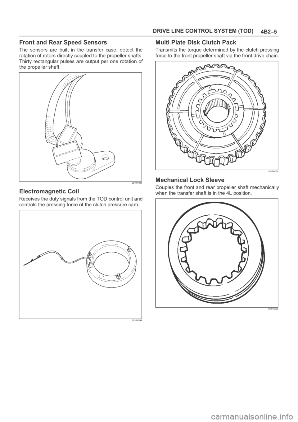
Front and Rear Speed Sensors
The sensors are built in the transfer case, detect the
rotation of rotors directly coupled to the propeller shafts.
Thirty rectangular pulses are output per one rotation of
the propeller shaft.
261RW045
Electromagnetic Coil
Receives the duty signals from the TOD control unit and
controls the pressing force of the clutch pressure cam.
261RW044
Multi Plate Disk Clutch Pack
Transmits the torque determined by the clutch pressing
force to the front propeller shaft via the front drive chain.
262RW029
Mechanical Lock Sleeve
Couples the front and rear propeller shaft mechanically
when the transfer shaft is in the 4L position.
262RW028
Page 577 of 6000
DRIVE LINE CONTROL SYSTEM (TOD) 4B2–6
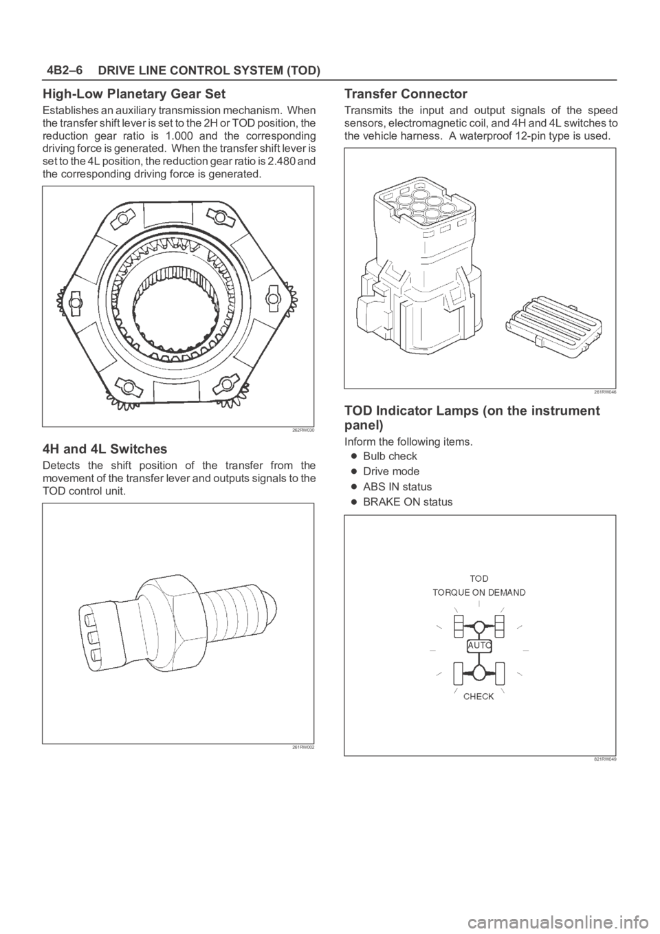
High-Low Planetary Gear Set
Establishes an auxiliary transmission mechanism. When
the transfer shift lever is set to the 2H or TOD position, the
reduction gear ratio is 1.000 and the corresponding
driving force is generated. When the transfer shift lever is
set to the 4L position, the reduction gear ratio is 2.480 and
the corresponding driving force is generated.
262RW030
4H and 4L Switches
Detects the shift position of the transfer from the
movement of the transfer lever and outputs signals to the
TOD control unit.
261RW002
Transfer Connector
Transmits the input and output signals of the speed
sensors, electromagnetic coil, and 4H and 4L switches to
the vehicle harness. A waterproof 12-pin type is used.
261RW046
TOD Indicator Lamps (on the instrument
panel)
Inform the following items.
Bulb check
Drive mode
ABS IN status
BRAKE ON status
821RW049