ESP OPEL FRONTERA 1998 Workshop Manual
[x] Cancel search | Manufacturer: OPEL, Model Year: 1998, Model line: FRONTERA, Model: OPEL FRONTERA 1998Pages: 6000, PDF Size: 97 MB
Page 281 of 6000

1. Perform oil return operation.
2. Discharge and recover the refrigerant and remove
the compressor.
3. Drain the compressor oil and measure the extracted
oil.
4. Check the compressor oil for contamination.
5. Adjust the oil level as required.
6. Evacuate, charge and perform the oil return
operation.
7. Check the system operation.
Contamination of Compressor Oil
Unlike engine oil, no cleaning agent is added to the
compressor oil. Even if the compressor runs for a long
period of time (approximately one season), the oil never
becomes contaminated as long as there is nothing
wrong with the compressor or its method of use.
Inspect the extracted oil for any of the following
conditions:
The capacity of the oil has increased.
The oil has changed to red.
Foreign substances, metal powder, etc., are present
in the oil.
If any of these conditions exists, the compressor
oil is contaminated. Whenever contaminated
compressor oil is discovered, the receiver/drier
must be replaced.
Oil Return Operation
There is close affinity between the oil and the
refrigerant. During normal operation, part of the oil
recirculates with the refrigerant in the system. When
checking the amount of oil in the system, or replacing
any component of the system, the compressor must be
run in advance for oil return operation. The procedure
is as follows:
1. Open all the doors and the engine hood.
2. Start the engine and air conditioning switch to "ON"
and set the fan control knob at its highest position.
3. Run the compressor for more than 20 minutes
between 800 and 1,000 rpm in order to operate the
system.
4. Stop the engine.
Replacement of Component Parts
When replacing the system component parts, supply
the following amount of oil to the component parts to be
installed.
Compressor Leak Testing (External and
Internal)
Bench-Check Procedure
1. Install test plate J-39893 on rear head of compressor.
2. Using Refrigerant Recovery System, attach center
hose of manifold gage set on charging station to a
refrigerant drum standing in an upright drum.
3. Connect charging station high and low pressure
lines to corresponding fittings on test plate J-39893.
Suction port (low-side) of compressor has large
internal opening. Discharge port (high-side) has
smaller internal opening into compressor and
deeper recess.
4. Open low pressure control, high pressure control
and refrigerant control on charging station to allow
refrigerant vapor to flow into compressor.
5. Using a leak detector, check for leaks at pressure
relief valve, rear head switch location, compressor
front and rear head seals, center cylinder seal,
through bolt head gaskets and compressor shaft
seal. After checking, shut off low pressure control
and high-pressure control on charging station.
6. If an external leak is present, perform the necessary
corrective measures and recheck for leaks to make
certain the leak has been connected.
7. Recover the refrigerant.
8. Disconnect both hoses from the test plate J-39893.
9. Add 90 ml (3 oz.) new PAG lubricant to the
compressor assembly. Rotate the complete
compressor assembly (not the crankshaft or drive
plate hub) slowly several turns to distribute oil to all
cylinder and piston areas.
10. Install a M9
1.25 threaded nut on the compressor
crankshaft if the drive plate and clutch assembly are
not installed.
11. Using a box-end wrench or socket and handle,
rotate the compressor crankshaft or clutch drive
plate on the crankshaft several turns to insure
piston assembly to cylinder wall lubrication.
12. Using Refrigerant Recovery System, connect the
charging station high-pressure line to the test plate
J-39893 high-side connector.
13. Using Refrigerant Recovery System, connect the
charging station low-pressure line to the low
pressure port of the test plate J-39893. Oil will drain
out of the compressor suction port if the compressor
is positioned with the suction port downward. (Component parts to be (Amount of Oil)
installed)
Evaporator 50 cc (1.7 fl. oz.)
Condenser 30 cc (1.0 fl. oz.)
Receiver/dryer 30 cc (1.0 fl. oz.)
Refrigerant line (one 10 cc (0.3 fl. oz.)
piece)
(Amount of oil drained (Charging amount of oil
from used compressor) to new compressor)
more than 90 cc same as drained amount
(3.0 fl.oz)
less than 90 cc (3.0 fl.oz) 90 cc (3.0 fl.oz)
Page 497 of 6000

4A2A–30
DIFFERENTIAL (REAR 220mm)
3. After measuring dimensions of each of the above
sections, proceed with the adjustment in the following
manner:
Adjust the clearance to satisfy the equation below.
{(F – B) + G – H}=0.05 – 0.20 mm
Also, select the thrust washers so that the
dimensional difference between the back surfaces of
the left and right pressure rings to the thrust washers
is 0.05mm or less.
Thickness : 1.5mm (0.059 in)
1.6 mm(0.063 in)
1.7 mm(0.067 in)
NOTE: When assembling the parts, apply recommended
gear oil sufficiently to each of the parts, especially, to the
contact surfaces and sliding surfaces.
1. Install Differential cage B.
2. Install Thrust washer.
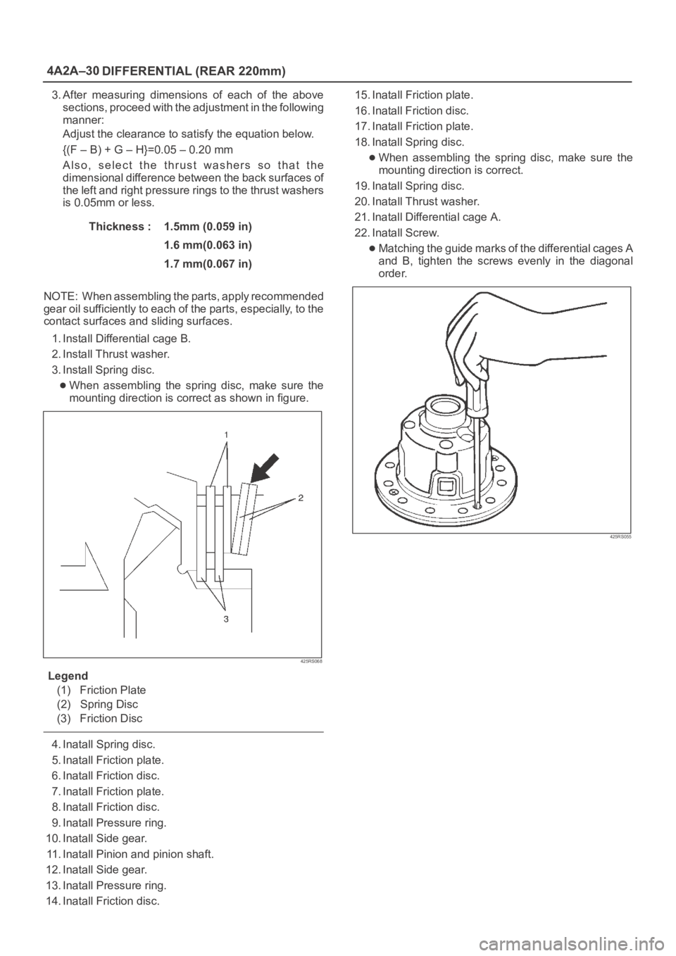
3. Install Spring disc.
When assembling the spring disc, make sure the
mounting direction is correct as shown in figure.
425RS068
Legend
(1) Friction Plate
(2) Spring Disc
(3) Friction Disc
4. Inatall Spring disc.
5. Inatall Friction plate.
6. Inatall Friction disc.
7. Inatall Friction plate.
8. Inatall Friction disc.
9. Inatall Pressure ring.
10. Inatall Side gear.
11. Inatall Pinion and pinion shaft.
12. Inatall Side gear.
13. Inatall Pressure ring.
14. Inatall Friction disc.15. Inatall Friction plate.
16. Inatall Friction disc.
17. Inatall Friction plate.
18. Inatall Spring disc.
When assembling the spring disc, make sure the
mounting direction is correct.
19. Inatall Spring disc.
20. Inatall Thrust washer.
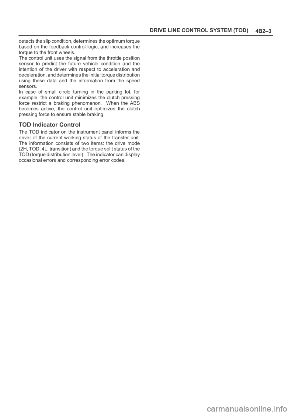
21. Inatall Differential cage A.
22. Inatall Screw.
Matching the guide marks of the differential cages A
and B, tighten the screws evenly in the diagonal
order.
425RS055
Page 574 of 6000

4B2–3 DRIVE LINE CONTROL SYSTEM (TOD)
detects the slip condition, determines the optimum torque
based on the feedback control logic, and increases the
torque to the front wheels.
The control unit uses the signal from the throttle position
sensor to predict the future vehicle condition and the
intention of the driver with respect to acceleration and
deceleration, and determines the initial torque distribution
using these data and the information from the speed
sensors.
In case of small circle turning in the parking lot, for
example, the control unit minimizes the clutch pressing
force restrict a braking phenomenon. When the ABS
becomes active, the control unit optimizes the clutch
pressing force to ensure stable braking.
TOD Indicator Control
The TOD indicator on the instrument panel informs the
driver of the current working status of the transfer unit.
The information consists of two items: the drive mode
(2H, TOD, 4L, transition) and the torque split status of the
TOD (torque distribution level). The indicator can display
occasional errors and corresponding error codes.
Page 577 of 6000

DRIVE LINE CONTROL SYSTEM (TOD) 4B2–6
High-Low Planetary Gear Set
Establishes an auxiliary transmission mechanism. When
the transfer shift lever is set to the 2H or TOD position, the
reduction gear ratio is 1.000 and the corresponding
driving force is generated. When the transfer shift lever is
set to the 4L position, the reduction gear ratio is 2.480 and
the corresponding driving force is generated.
262RW030
4H and 4L Switches
Detects the shift position of the transfer from the
movement of the transfer lever and outputs signals to the
TOD control unit.
261RW002
Transfer Connector
Transmits the input and output signals of the speed
sensors, electromagnetic coil, and 4H and 4L switches to
the vehicle harness. A waterproof 12-pin type is used.
261RW046
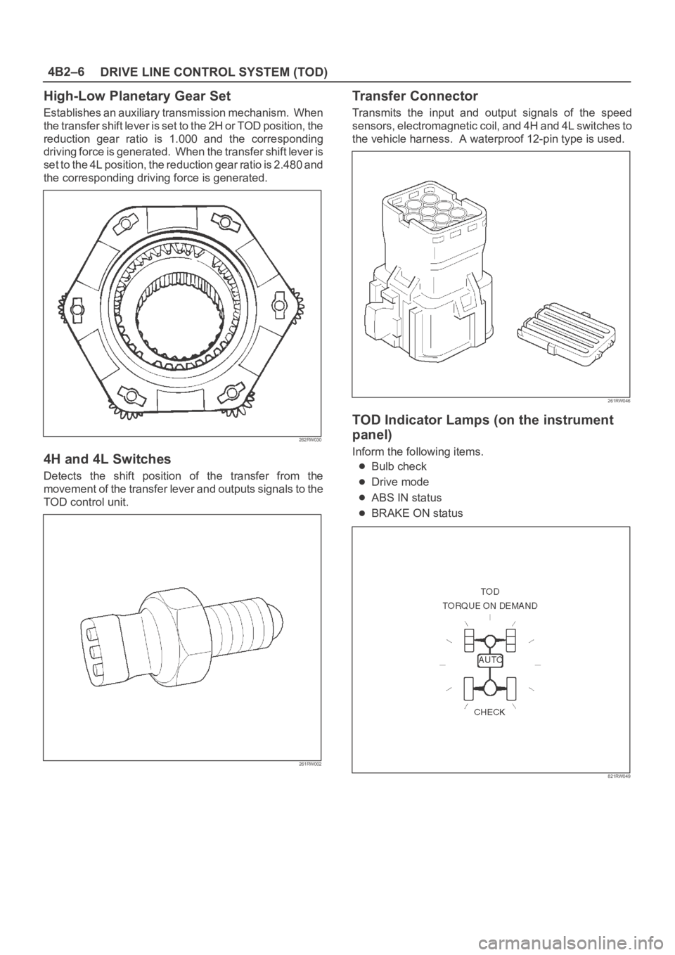
TOD Indicator Lamps (on the instrument
panel)
Inform the following items.
Bulb check
Drive mode
ABS IN status
BRAKE ON status
821RW049
Page 582 of 6000

4B2–11 DRIVE LINE CONTROL SYSTEM (TOD)
The CHECK lamp also has the following functions.
D-G MAP recognition and display (The control unit
displays what type of vehicle, diesel or gasoline
vehicle, it recognizes.)
1. Short-circuit the self-diagnostic connector.
2. Turn on the starter switch. (Displays with respect to
the self-diagnosis begin to appear.)
NOTE: Do not start the engine.
3. Shift the transfer lever to the neutral position between
HIGH and 4L.
4. After all the conditions in 1 through 3 above are met,
set the throttle to the WOT (wide open throttle)
position (i.e., full open position). The display of the
self-diagnosis is temporarily suspended, and the
CHECK lamp begins to display that MAP is
recognized by the TPS (throttle position sensor)
according to the current conditions.NOTE: If the TPS has failed, this function might not work.
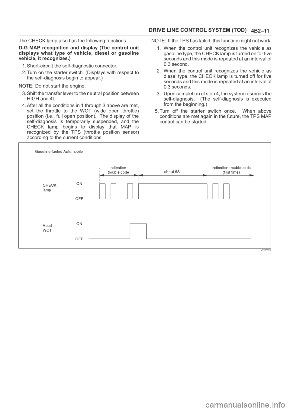
1. When the control unit recognizes the vehicle as
gasoline type, the CHECK lamp is turned on for five
seconds and this mode is repeated at an interval of
0.3 second.
2. When the control unit recognizes the vehicle as
diesel type, the CHECK lamp is turned off for five
seconds and this mode is repeated at an interval of
0.3 seconds.
3. Upon completion of step 4, the system resumes the
self-diagnosis. (The self-diagnosis is executed
from the beginning.)
5. Turn off the starter switch once. When above
conditions are met again in the future, the TPS MAP
control can be started.
C04RW010
Page 584 of 6000

4B2–13 DRIVE LINE CONTROL SYSTEM (TOD)
Indication Method of Trouble Code
Short-circuit terminal 8 of the self-diagnostic
connector to GND to display the trouble code on the
CHECK lamp.
810RW308
If no trouble codes exist, code “12” is displayed
continuously.
If trouble codes exist, code “12” is displayed three
times, and the trouble codes, starting from the smaller
code number, are displayed three times respectively.
C07RW013
Page 605 of 6000

DRIVE LINE CONTROL SYSTEM (TOD) 4B2–34
Check flowTrouble codePhenomenonStandard
316The front speed sensor no pulse.Hi level : 4.5 6.0 V
Lo level : 0.7
2.0 V
Frequency (F) =
GAS: 832 Hz (at 50 km/h)
NOTE: Find the trouble in which the pulse corresponding
to the running speed is not input.
D04RW061
Page 607 of 6000

DRIVE LINE CONTROL SYSTEM (TOD) 4B2–36
Check flowTrouble codePhenomenonStandard
427The rear speed sensor no pulse.Hi level : 4.5 6.0 V
Lo level : 0.7
2.0 V
Frequency (F) =
832 Hz (at 50 km/h)
NOTE: Find the trouble in which the pulse corresponding
to the running speed is not input.
D04RW060
Page 679 of 6000

4C–13 DRIVE SHAFT SYSTEM
9. Install lock washer and lock screw in the following
manner.
Turn the side with larger diameter of the tapered
bore to the vehicle outer side, then attach the
washer.
If the bolt holes in the lock plate are not aligned with
the corresponding holes in the nut, reverse the lock
plate.
If the bolt holes are still out of alignment, turn in the
nut just enough to obtain alignment.
Screw is to be fastened tightly so its head may
come lower than the surface of the washer.
411RS012
10. Apply adhesive (LOCTITE 515 or equivalent) to both
joining flange faces then install hub flange.
11. Install snap ring and shim.
Adjust the clearance between the free wheeling hub
body and the snap ring.
Clearance: 0 mm–0.3 mm (0 in–0.012 in)
Shims Available: 0.2 mm, 0.3 mm, 0.5 mm,
1.0 mm (0.008 in, 0.012 in, 0.020 in, 0.039 in)
411RW002
12. Install hub cap.
13. Tighten the bolts to the specified torque.
Torque: 59 Nꞏm (6.0 kgꞏm/43 lb ft)
Page 685 of 6000

4C–19 DRIVE SHAFT SYSTEM
21. Install lock washer and lock screw in the following
manner.
Turn the side with larger diameter of the tapered
bore to the vehicle outer side, and attach the
washer.
If the bolt holes in the lock plate are not aligned with
the corresponding holes in the nut, reverse the lock
plate.
If the bolt holes are still out of alignment, trun in the
nut just enough to obtain alignment.
Screw is to be fastened tightly so its head may
come lower than the surface of the washer.
411RS012
22. Install body assembly.
Apply adhesive (LOCTITE 515 or equivalent) to
both joining faces.
Tighten the bolts to the specified torque.
Torque:59Nꞏm (6.0kgꞏm/43lbft)
23. Install snap ring and shim.
Adjust the clearance between the free wheeling hub
body and the snap ring.
Clearance:
0-0.3mm (0-0.012in)
Shims Available:
0.2mm, 0.3mm, 0.5mm, 1.0mm, (0.008in, 0.012in,
0.020in, 0.039in)
411RW002
24. Install cover assembly.
Align stopper nails (1) to grooves of body (2).
411RW019
25. Tighten the cover bolts to the specified torque.
Torque:12Nꞏm (1.2kgꞏm/104lbin)