ECU OPEL FRONTERA 1998 Workshop Manual
[x] Cancel search | Manufacturer: OPEL, Model Year: 1998, Model line: FRONTERA, Model: OPEL FRONTERA 1998Pages: 6000, PDF Size: 97 MB
Page 4960 of 6000
6E–303 ENGINE DRIVEABILITY AND EMISSIONS
4. Check the transfer case oil level. Add fluid if
necessary.
5. Connect the negative battery cable.
Air Cleaner/Air Filter
Removal Procedure
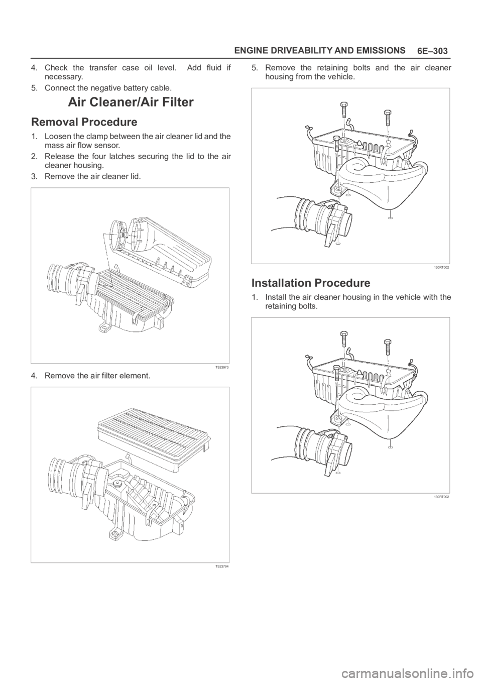
1. Loosen the clamp between the air cleaner lid and the
mass air flow sensor.
2. Release the four latches securing the lid to the air
cleaner housing.
3. Remove the air cleaner lid.
TS23973
4. Remove the air filter element.
TS23794
5. Remove the retaining bolts and the air cleaner
housing from the vehicle.
130RT002
Installation Procedure
1. Install the air cleaner housing in the vehicle with the
retaining bolts.
130RT002
Page 4961 of 6000
6E–304
ENGINE DRIVEABILITY AND EMISSIONS
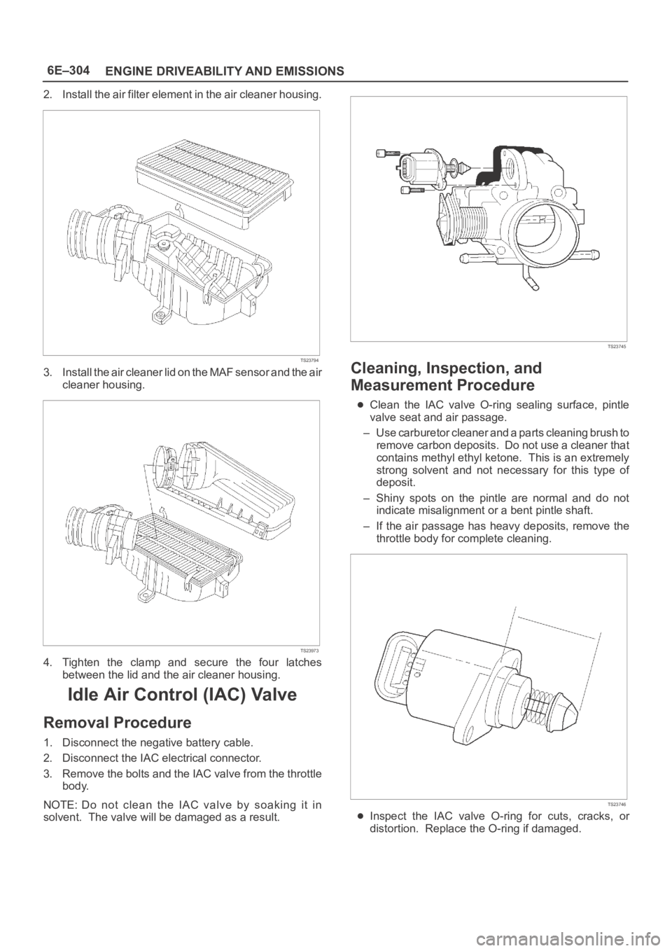
2. Install the air filter element in the air cleaner housing.
TS23794
3. Install the air cleaner lid on the MAF sensor and the air
cleaner housing.
TS23973
4. Tighten the clamp and secure the four latches
between the lid and the air cleaner housing.
Idle Air Control (IAC) Valve
Removal Procedure
1. Disconnect the negative battery cable.
2. Disconnect the IAC electrical connector.
3. Remove the bolts and the IAC valve from the throttle
body.
NOTE: Do not clean the IAC valve by soaking it in
solvent. The valve will be damaged as a result.
TS23745
Cleaning, Inspection, and
Measurement Procedure
Clean the IAC valve O-ring sealing surface, pintle
valve seat and air passage.
– Use carburetor cleaner and a parts cleaning brush to
remove carbon deposits. Do not use a cleaner that
contains methyl ethyl ketone. This is an extremely
strong solvent and not necessary for this type of
deposit.
– Shiny spots on the pintle are normal and do not
indicate misalignment or a bent pintle shaft.
– If the air passage has heavy deposits, remove the
throttle body for complete cleaning.
TS23746
Inspect the IAC valve O-ring for cuts, cracks, or
distortion. Replace the O-ring if damaged.
Page 4973 of 6000
6E–316
ENGINE DRIVEABILITY AND EMISSIONS
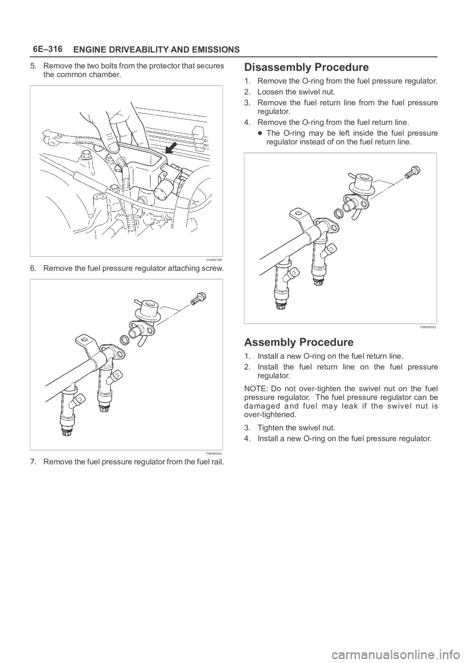
5. Remove the two bolts from the protector that secures
the common chamber.
014RW109
6. Remove the fuel pressure regulator attaching screw.
F06RW043
7. Remove the fuel pressure regulator from the fuel rail.
Disassembly Procedure
1. Remove the O-ring from the fuel pressure regulator.
2. Loosen the swivel nut.
3. Remove the fuel return line from the fuel pressure
regulator.
4. Remove the O-ring from the fuel return line.
The O-ring may be left inside the fuel pressure
regulator instead of on the fuel return line.
F06RW043
Assembly Procedure
1. Install a new O-ring on the fuel return line.
2. Install the fuel return line on the fuel pressure
regulator.
NOTE: Do not over-tighten the swivel nut on the fuel
pressure regulator. The fuel pressure regulator can be
damaged and fuel may leak if the swivel nut is
over-tightened.
3. Tighten the swivel nut.
4. Install a new O-ring on the fuel pressure regulator.
Page 4974 of 6000
6E–317 ENGINE DRIVEABILITY AND EMISSIONS
Installation Procedure
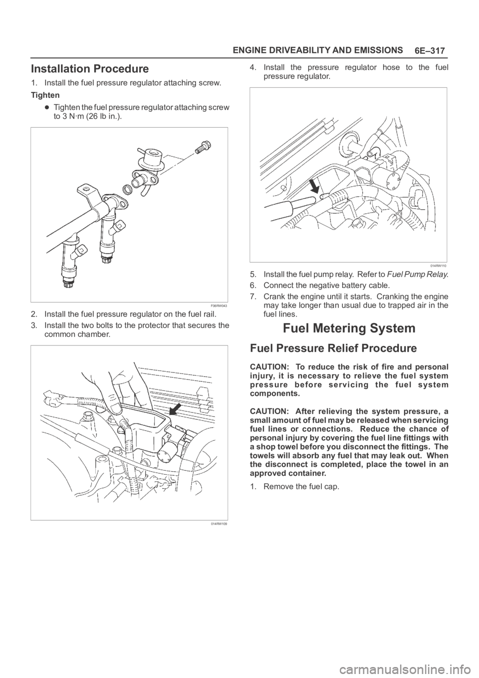
1. Install the fuel pressure regulator attaching screw.
Tighten
Tighten the fuel pressure regulator attaching screw
to 3 Nꞏm (26 lb in.).
F06RW043
2. Install the fuel pressure regulator on the fuel rail.
3. Install the two bolts to the protector that secures the
common chamber.
014RW109
4. Install the pressure regulator hose to the fuel
pressure regulator.
014RW110
5. Install the fuel pump relay. Refer to Fuel Pump Relay.
6. Connect the negative battery cable.
7. Crank the engine until it starts. Cranking the engine
may take longer than usual due to trapped air in the
fuel lines.
Fuel Metering System
Fuel Pressure Relief Procedure
CAUTION: To reduce the risk of fire and personal
injury, it is necessary to relieve the fuel system
pressure before servicing the fuel system
components.
CAUTION: After relieving the system pressure, a
small amount of fuel may be released when servicing
fuel lines or connections. Reduce the chance of
personal injury by covering the fuel line fittings with
a shop towel before you disconnect the fittings. The
towels will absorb any fuel that may leak out. When
the disconnect is completed, place the towel in an
approved container.
1. Remove the fuel cap.
Page 4979 of 6000
6E–322
ENGINE DRIVEABILITY AND EMISSIONS
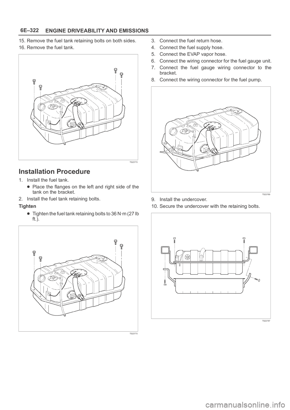
15. Remove the fuel tank retaining bolts on both sides.
16. Remove the fuel tank.
TS23770
Installation Procedure
1. Install the fuel tank.
Place the flanges on the left and right side of the
tank on the bracket.
2. Install the fuel tank retaining bolts.
Tighten
Tighten the fuel tank retaining bolts to 36 Nꞏm (27 lb
ft.).
TS23770
3. Connect the fuel return hose.
4. Connect the fuel supply hose.
5. Connect the EVAP vapor hose.
6. Connect the wiring connector for the fuel gauge unit.
7. Connect the fuel gauge wiring connector to the
bracket.
8. Connect the wiring connector for the fuel pump.
TS23769
9. Install the undercover.
10. Secure the undercover with the retaining bolts.
TS23797
Page 4981 of 6000
6E–324
ENGINE DRIVEABILITY AND EMISSIONS
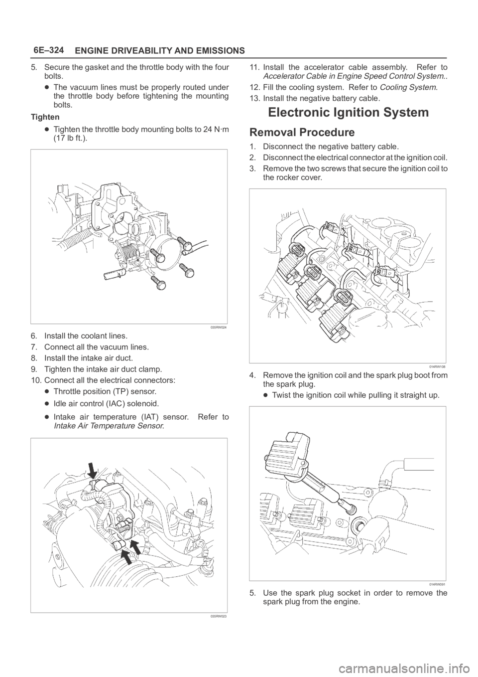
5. Secure the gasket and the throttle body with the four
bolts.
The vacuum lines must be properly routed under
the throttle body before tightening the mounting
bolts.
Tighten
Tighten the throttle body mounting bolts to 24 Nꞏm
(17 lb ft.).
035RW024
6. Install the coolant lines.
7. Connect all the vacuum lines.
8. Install the intake air duct.
9. Tighten the intake air duct clamp.
10. Connect all the electrical connectors:
Throttle position (TP) sensor.
Idle air control (IAC) solenoid.
Intake air temperature (IAT) sensor. Refer to
Intake Air Temperature Sensor.
035RW023
11. Install the accelerator cable assembly. Refer to
Accelerator Cable in Engine Speed Control System..
12. Fill the cooling system. Refer to
Cooling System.
13. Install the negative battery cable.
Electronic Ignition System
Removal Procedure
1. Disconnect the negative battery cable.
2. Disconnect the electrical connector at the ignition coil.
3. Remove the two screws that secure the ignition coil to
the rocker cover.
014RW108
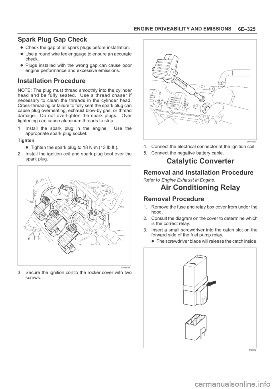
4. Remove the ignition coil and the spark plug boot from
the spark plug.
Twist the ignition coil while pulling it straight up.
014RW091
5. Use the spark plug socket in order to remove the
spark plug from the engine.
Page 4982 of 6000
6E–325 ENGINE DRIVEABILITY AND EMISSIONS
Spark Plug Gap Check
Check the gap of all spark plugs before installation.
Use a round wire feeler gauge to ensure an accurate
check.
Plugs installed with the wrong gap can cause poor
engine performance and excessive emissions.
Installation Procedure
NOTE: The plug must thread smoothly into the cylinder
head and be fully seated. Use a thread chaser if
necessary to clean the threads in the cylinder head.
Cross-threading or failure to fully seat the spark plug can
cause plug overheating, exhaust blow-by gas, or thread
damage. Do not overtighten the spark plugs. Over
tightening can cause aluminum threads to strip.
1. Install the spark plug in the engine. Use the
appropriate spark plug socket.
Tighten
Tighten the spark plug to 18 Nꞏm (13 lb ft.).
2. Install the ignition coil and spark plug boot over the
spark plug.
014RW108
3. Secure the ignition coil to the rocker cover with two
screws.
014RW091
4. Connect the electrical connector at the ignition coil.
5. Connect the negative battery cable.
Catalytic Converter
Removal and Installation Procedure
Refer to Engine Exhaust in Engine.
Air Conditioning Relay
Removal Procedure
1. Remove the fuse and relay box cover from under the
hood.
2. Consult the diagram on the cover to determine which
is the correct relay.
3. Insert a small screwdriver into the catch slot on the
forward side of the fuel pump relay.
The screwdriver blade will release the catch inside.
T321092
Page 4985 of 6000
6E–328
ENGINE DRIVEABILITY AND EMISSIONS
3. Connect the vacuum hoses to the EVAP canister
purge solenoid.
014RW137
4. Connect the electrical connector to the EVAP canister
purge solenoid.
014RW138
Fuel Tank Vent Valve
Removal and Installation Procedure
Refer to Fuel Pump
Linear Exhaust Gas
Recirculation (EGR) Valve
Removal Procedure
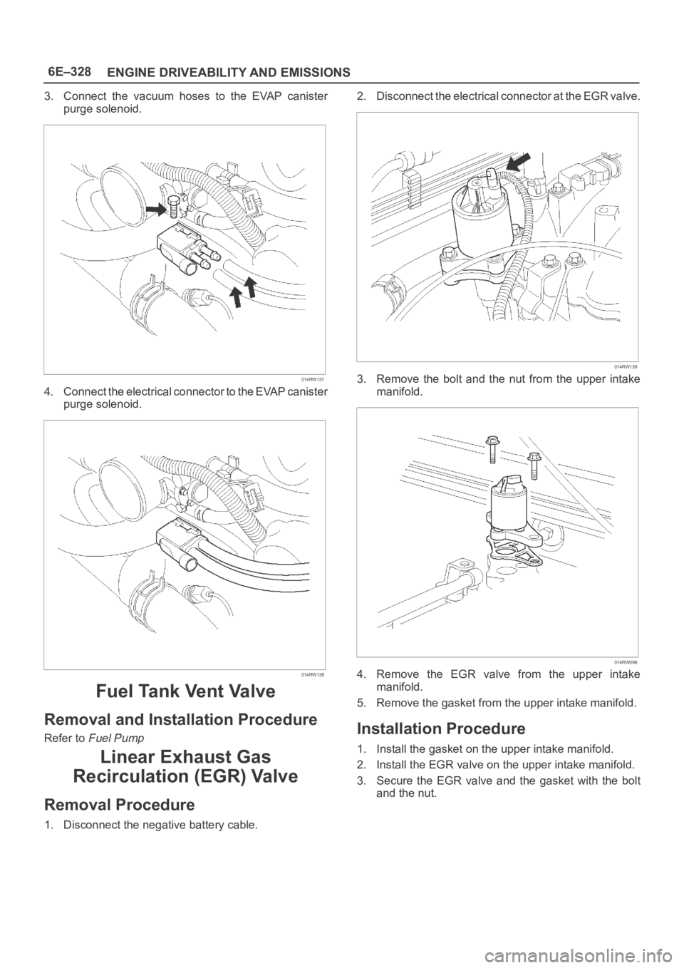
1. Disconnect the negative battery cable.2. Disconnect the electrical connector at the EGR valve.
014RW139
3. Remove the bolt and the nut from the upper intake
manifold.
014RW098
4. Remove the EGR valve from the upper intake
manifold.
5. Remove the gasket from the upper intake manifold.
Installation Procedure
1. Install the gasket on the upper intake manifold.
2. Install the EGR valve on the upper intake manifold.
3. Secure the EGR valve and the gasket with the bolt
and the nut.
Page 4986 of 6000
6E–329 ENGINE DRIVEABILITY AND EMISSIONS
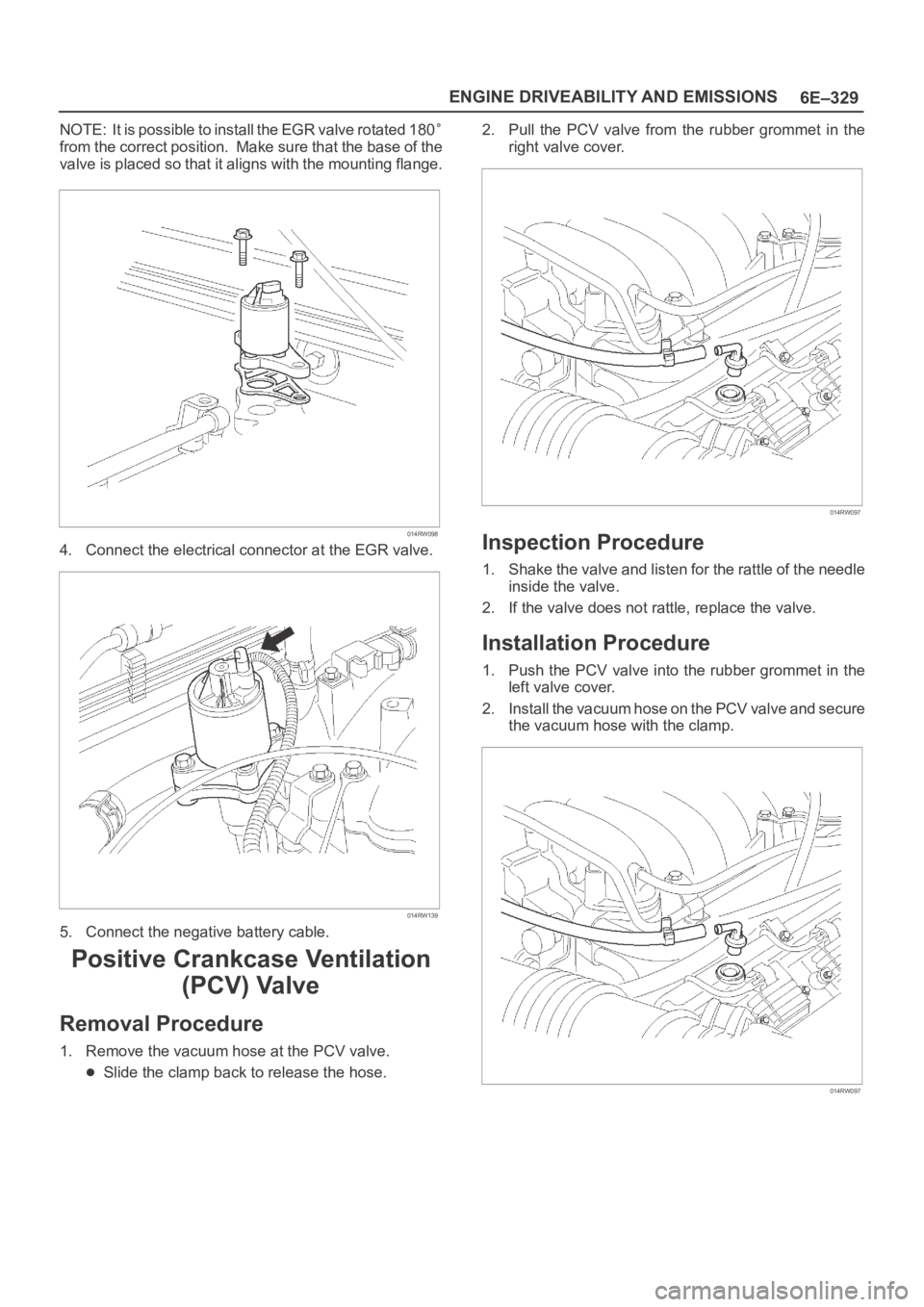
NOTE: It is possible to install the EGR valve rotated 180
from the correct position. Make sure that the base of the
valve is placed so that it aligns with the mounting flange.
014RW098
4. Connect the electrical connector at the EGR valve.
014RW139
5. Connect the negative battery cable.
Positive Crankcase Ventilation
(PCV) Valve
Removal Procedure
1. Remove the vacuum hose at the PCV valve.
Slide the clamp back to release the hose.2. Pull the PCV valve from the rubber grommet in the
right valve cover.
014RW097
Inspection Procedure
1. Shake the valve and listen for the rattle of the needle
inside the valve.
2. If the valve does not rattle, replace the valve.
Installation Procedure
1. Push the PCV valve into the rubber grommet in the
left valve cover.
2. Install the vacuum hose on the PCV valve and secure
the vacuum hose with the clamp.
014RW097
Page 4988 of 6000
6E–331 ENGINE DRIVEABILITY AND EMISSIONS
Installation Procedure
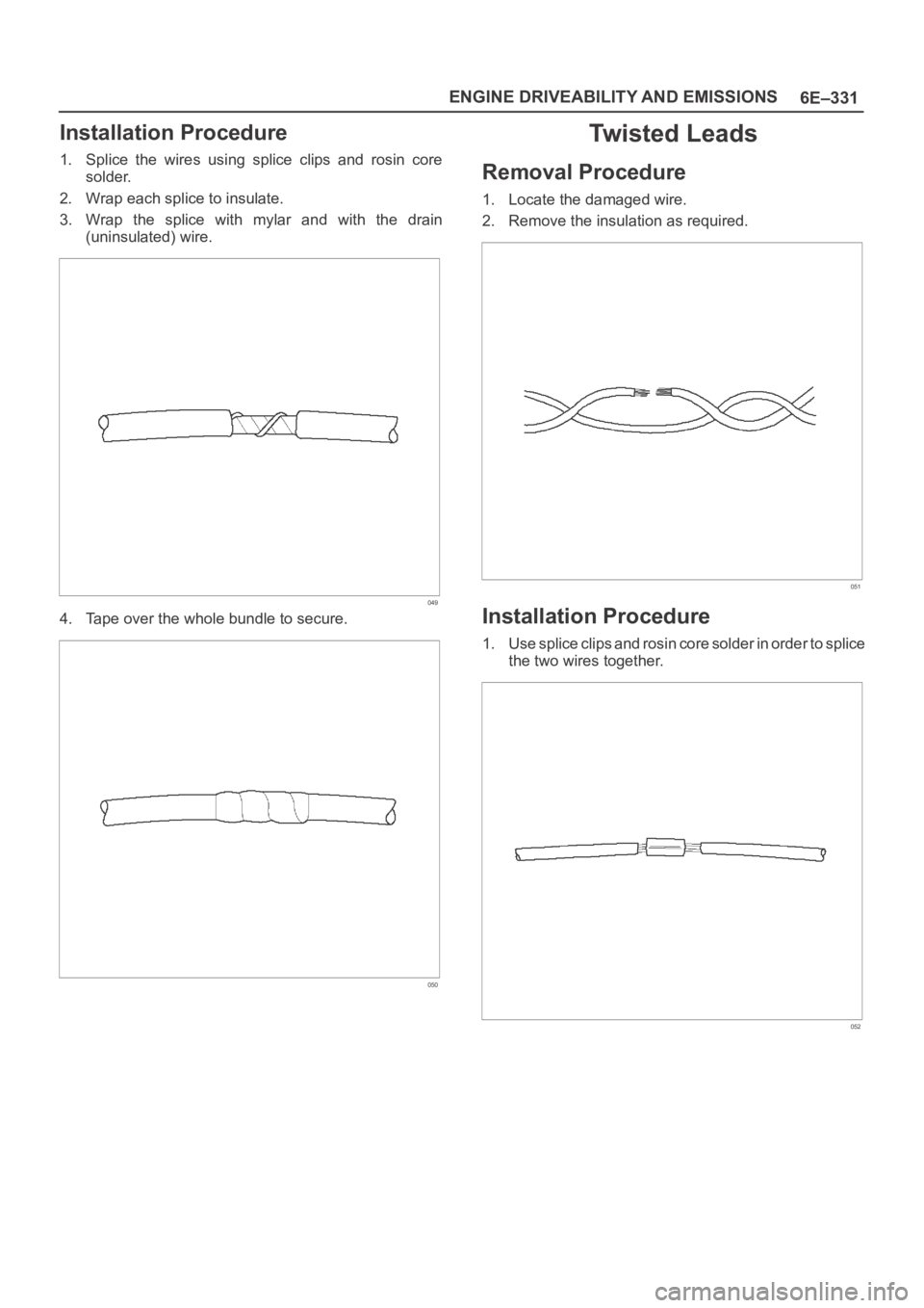
1. Splice the wires using splice clips and rosin core
solder.
2. Wrap each splice to insulate.
3. Wrap the splice with mylar and with the drain
(uninsulated) wire.
049
4. Tape over the whole bundle to secure.
050
Twisted Leads
Removal Procedure
1. Locate the damaged wire.
2. Remove the insulation as required.
051
Installation Procedure
1. Use splice clips and rosin core solder in order to splice
the two wires together.
052