relay OPEL FRONTERA 1998 Workshop Manual
[x] Cancel search | Manufacturer: OPEL, Model Year: 1998, Model line: FRONTERA, Model: OPEL FRONTERA 1998Pages: 6000, PDF Size: 97 MB
Page 4903 of 6000
6E–246
ENGINE DRIVEABILITY AND EMISSIONS
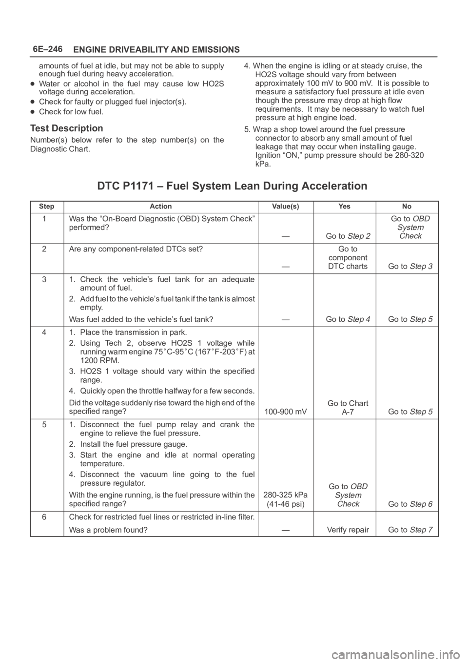
amounts of fuel at idle, but may not be able to supply
enough fuel during heavy acceleration.
Water or alcohol in the fuel may cause low HO2S
voltage during acceleration.
Check for faulty or plugged fuel injector(s).
Check for low fuel.
Test Description
Number(s) below refer to the step number(s) on the
Diagnostic Chart.4. When the engine is idling or at steady cruise, the
HO2S voltage should vary from between
approximately 100 mV to 900 mV. It is possible to
measure a satisfactory fuel pressure at idle even
though the pressure may drop at high flow
requirements. It may be necessary to watch fuel
pressure at high engine load.
5. Wrap a shop towel around the fuel pressure
connector to absorb any small amount of fuel
leakage that may occur when installing gauge.
Ignition “ON,” pump pressure should be 280-320
kPa.
DTC P1171 – Fuel System Lean During Acceleration
StepActionVa l u e ( s )Ye sNo
1Was the “On-Board Diagnostic (OBD) System Check”
performed?
—Go to Step 2
Go to OBD
System
Check
2Are any component-related DTCs set?
—
Go to
component
DTC charts
Go to Step 3
31. Check the vehicle’s fuel tank for an adequate
amount of fuel.
2. Add fuel to the vehicle’s fuel tank if the tank is almost
empty.
Was fuel added to the vehicle’s fuel tank?
—Go to Step 4Go to Step 5
41. Place the transmission in park.
2. Using Tech 2, observe HO2S 1 voltage while
running warm engine 75
C-95C (167F-203F) at
1200 RPM.
3. HO2S 1 voltage should vary within the specified
range.
4. Quickly open the throttle halfway for a few seconds.
Did the voltage suddenly rise toward the high end of the
specified range?
100-900 mV
Go to Chart
A-7
Go to Step 5
51. Disconnect the fuel pump relay and crank the
engine to relieve the fuel pressure.
2. Install the fuel pressure gauge.
3. Start the engine and idle at normal operating
temperature.
4. Disconnect the vacuum line going to the fuel
pressure regulator.
With the engine running, is the fuel pressure within the
specified range?
280-325 kPa
(41-46 psi)
Go to OBD
System
Check
Go to Step 6
6Check for restricted fuel lines or restricted in-line filter.
Was a problem found?
—Verify repairGo to Step 7
Page 4904 of 6000
6E–247 ENGINE DRIVEABILITY AND EMISSIONS
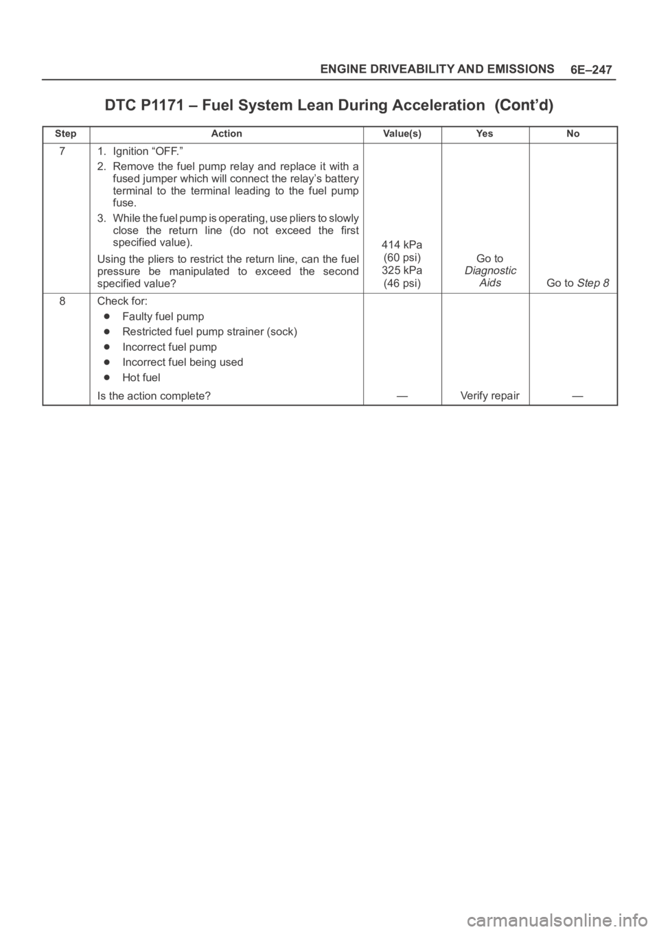
DTC P1171 – Fuel System Lean During Acceleration
StepNo Ye s Va l u e ( s ) Action
71. Ignition “OFF.”
2. Remove the fuel pump relay and replace it with a
fused jumper which will connect the relay’s battery
terminal to the terminal leading to the fuel pump
fuse.
3. While the fuel pump is operating, use pliers to slowly
close the return line (do not exceed the first
specified value).
Using the pliers to restrict the return line, can the fuel
pressure be manipulated to exceed the second
specified value?
414 kPa
(60 psi)
325 kPa
(46 psi)
Go to
Diagnostic
Aids
Go to Step 8
8Check for:
Faulty fuel pump
Restricted fuel pump strainer (sock)
Incorrect fuel pump
Incorrect fuel being used
Hot fuel
Is the action complete?
—Verify repair—
Page 4916 of 6000
6E–259 ENGINE DRIVEABILITY AND EMISSIONS
Diagnostic Trouble Code (DTC) P1640 Driver-1-Input High Voltage
Circuit Description
Output driver modules (ODMs) are used by the
powertrain control module (PCM) to turn “ON” many of
the current-driven devices that are needed to control
various engine and transmission functions. Each ODM is
capable of controlling up to 7 separate outputs by
applying ground to the device which the PCM is
commanding “ON.”
Unlike the Quad Driver Modules (QDMs) used in prior
model years, ODMs have the capability of diagnosing
each output circuit individually. DTC P1640 set indicates
an improper voltage level has been detected on an ODM
output.
Since A/C is an option, No A/C will cause the air
conditioning clutch relay output to always fault. If a fault is
seen on the air conditioning clutch relay output, it will not
be logged as a fault until the A/C request input interrupts a
high voltage, indicating that A/C has been installed.
Conditions for Setting the DTC
Ignition “ON.”
Engine running.
No DTC 1618.
Ignition voltage is above 13.2 volts for 4 seconds.
Output voltage does not equal ignition voltage when
output is “OFF” or output voltage is not less than 1 volt
when output is “ON.”
Above conditions occur for at least 1 second.
Action Taken When the DTC Sets
The PCM will not illuminate the malfunction indicator
lamp (MIL).
The PCM will store conditions which were present
when the DTC was set as Failure Records only. This
information will not be stored as Freeze Frame data.
Conditions for Clearing the MIL/DTC
DTC P1640 can be cleared by using the Tech 2 “Clear
Info” function or by disconnecting the PCM battery
feed.
Diagnostic Aids
Check for the following conditions:
Poor connection at PCM – Inspect harness connectors
for backed-out terminals, improper mating, broken
locks, improperly formed or damaged terminals, and
poor terminal-to-wire connection.
Damaged harness – Inspect the wiring harness for
damage, If the harness appears to be OK, disconnect
the PCM, turn the ignition “ON” and observe a
voltmeter connected to the suspect driver circuit at the
PCM harness connector while moving connectors and
wiring harnesses relates to the MIL. A change in
voltage will indicate the location of the fault.
Poor connection at component – Examine for
damaged connectors, unplugged connector, or
damaged terminals at the following locations:
Instrument cluster harness, canister purge solenoid,
A/C clutch relay. An open ignition feed circuit at any of
these components will cause DTC P1640 to be set.
Reviewing the Failure Records vehicle mileage since the
diagnostic test last failed may help determine how often
the condition that caused the DTC to be set occurs. This
may assist in diagnosing the condition.
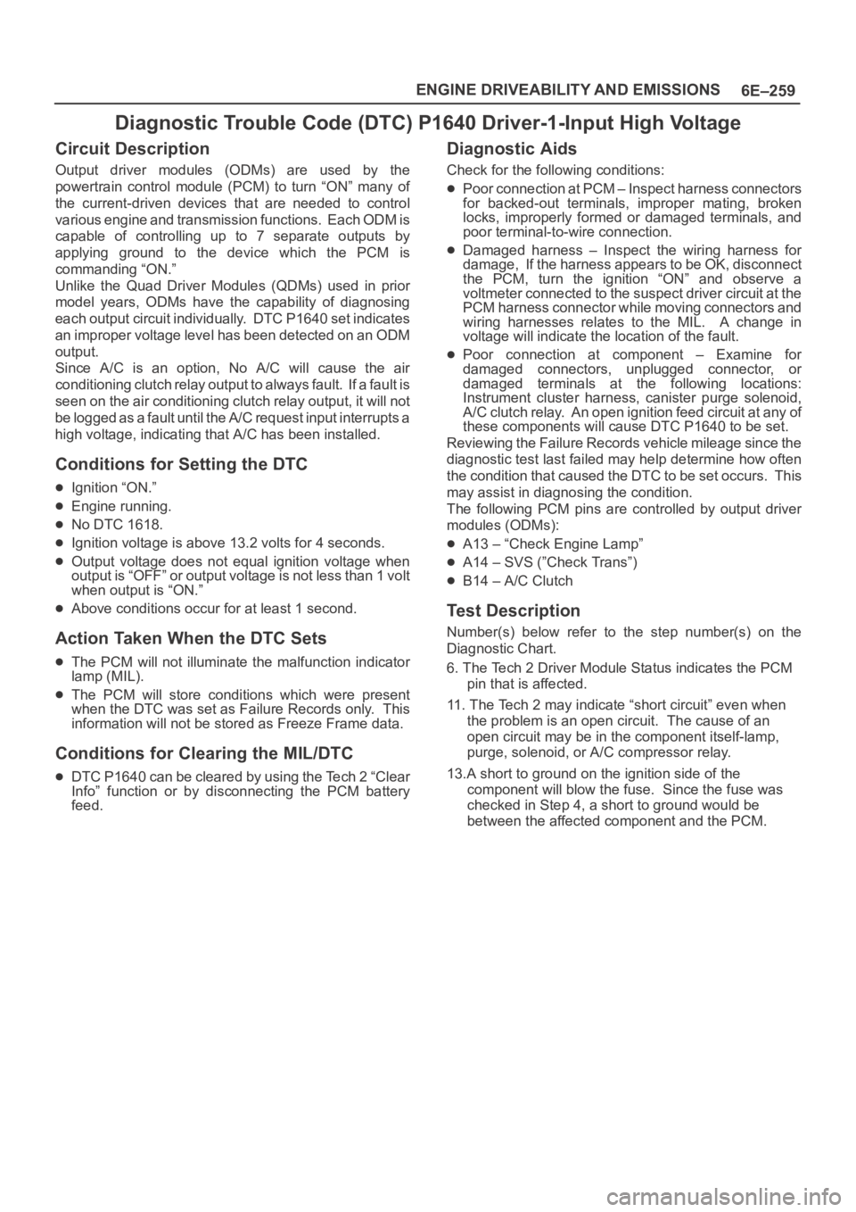
The following PCM pins are controlled by output driver
modules (ODMs):
A13 – “Check Engine Lamp”
A14 – SVS (”Check Trans”)
B14 – A/C Clutch
Test Description
Number(s) below refer to the step number(s) on the
Diagnostic Chart.
6. The Tech 2 Driver Module Status indicates the PCM
pin that is affected.
11. The Tech 2 may indicate “short circuit” even when
the problem is an open circuit. The cause of an
open circuit may be in the component itself-lamp,
purge, solenoid, or A/C compressor relay.
13.A short to ground on the ignition side of the
component will blow the fuse. Since the fuse was
checked in Step 4, a short to ground would be
between the affected component and the PCM.
Page 4972 of 6000
6E–315 ENGINE DRIVEABILITY AND EMISSIONS
Installation Procedure
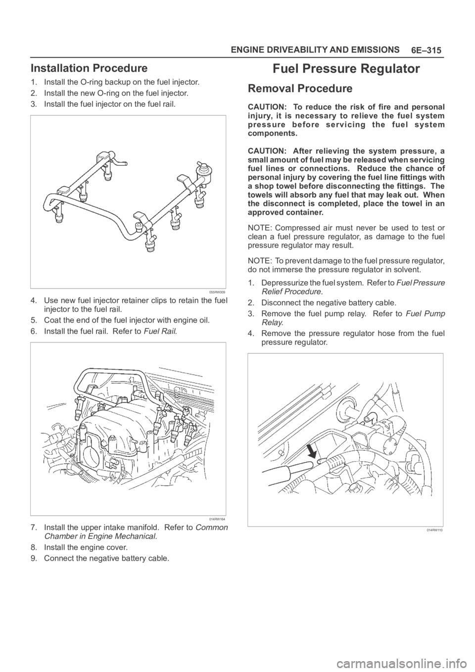
1. Install the O-ring backup on the fuel injector.
2. Install the new O-ring on the fuel injector.
3. Install the fuel injector on the fuel rail.
055RW009
4. Use new fuel injector retainer clips to retain the fuel
injector to the fuel rail.
5. Coat the end of the fuel injector with engine oil.
6. Install the fuel rail. Refer to
Fuel Rail.
014RW164
7. Install the upper intake manifold. Refer to Common
Chamber in Engine Mechanical.
8. Install the engine cover.
9. Connect the negative battery cable.
Fuel Pressure Regulator
Removal Procedure
CAUTION: To reduce the risk of fire and personal
injury, it is necessary to relieve the fuel system
pressure before servicing the fuel system
components.
CAUTION: After relieving the system pressure, a
small amount of fuel may be released when servicing
fuel lines or connections. Reduce the chance of
personal injury by covering the fuel line fittings with
a shop towel before disconnecting the fittings. The
towels will absorb any fuel that may leak out. When
the disconnect is completed, place the towel in an
approved container.
NOTE: Compressed air must never be used to test or
clean a fuel pressure regulator, as damage to the fuel
pressure regulator may result.
NOTE: To prevent damage to the fuel pressure regulator,
do not immerse the pressure regulator in solvent.
1. Depressurize the fuel system. Refer to
Fuel Pressure
Relief Procedure
.
2. Disconnect the negative battery cable.
3. Remove the fuel pump relay. Refer to
Fuel Pump
Relay
.
4. Remove the pressure regulator hose from the fuel
pressure regulator.
014RW110
Page 4974 of 6000
6E–317 ENGINE DRIVEABILITY AND EMISSIONS
Installation Procedure
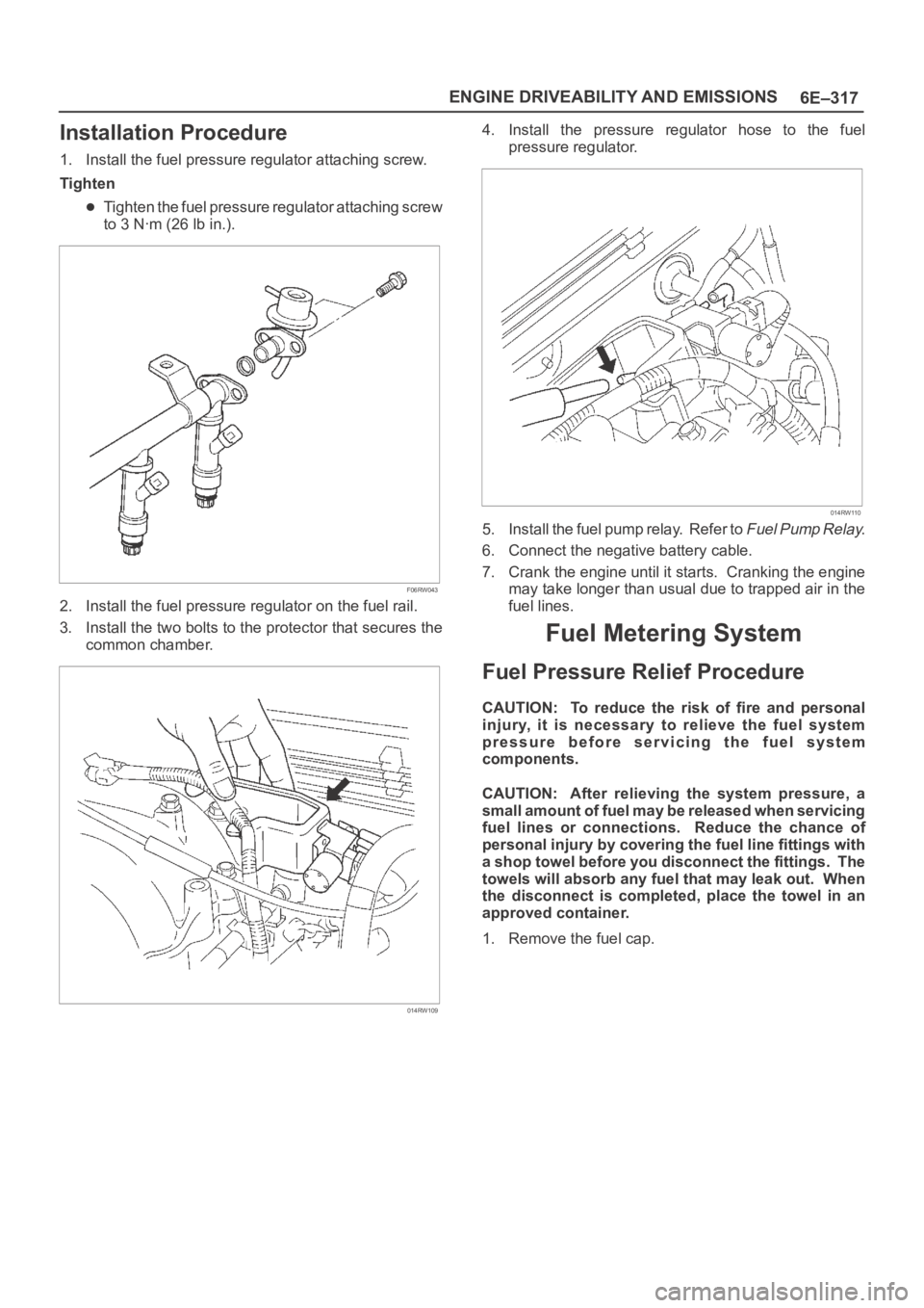
1. Install the fuel pressure regulator attaching screw.
Tighten
Tighten the fuel pressure regulator attaching screw
to 3 Nꞏm (26 lb in.).
F06RW043
2. Install the fuel pressure regulator on the fuel rail.
3. Install the two bolts to the protector that secures the
common chamber.
014RW109
4. Install the pressure regulator hose to the fuel
pressure regulator.
014RW110
5. Install the fuel pump relay. Refer to Fuel Pump Relay.
6. Connect the negative battery cable.
7. Crank the engine until it starts. Cranking the engine
may take longer than usual due to trapped air in the
fuel lines.
Fuel Metering System
Fuel Pressure Relief Procedure
CAUTION: To reduce the risk of fire and personal
injury, it is necessary to relieve the fuel system
pressure before servicing the fuel system
components.
CAUTION: After relieving the system pressure, a
small amount of fuel may be released when servicing
fuel lines or connections. Reduce the chance of
personal injury by covering the fuel line fittings with
a shop towel before you disconnect the fittings. The
towels will absorb any fuel that may leak out. When
the disconnect is completed, place the towel in an
approved container.
1. Remove the fuel cap.
Page 4975 of 6000
6E–318
ENGINE DRIVEABILITY AND EMISSIONS
2. Remove the fuel pump relay from the underhood
relay box. Refer to
Fuel Pump Relay.
TS23976R
3. Start the engine and allow it to stall.
4. Crank the engine for 30 seconds.
5. Disconnect the negative battery cable.
Fuel Pump Assembly
Removal Procedure
1. Disconnect the negative battery cable.
2. Drain all the fuel from the tank.
3. Install and tighten the drain plug.
Tighten
Tighten the drain plug to 20 Nꞏm (14 lb ft.).
4. Remove the fuel tank. Refer to
Fuel Tank.
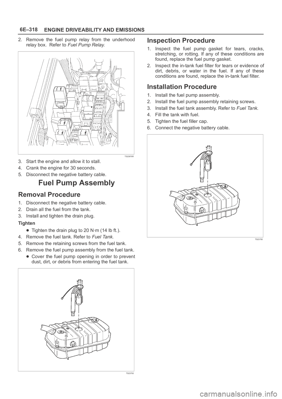
5. Remove the retaining screws from the fuel tank.
6. Remove the fuel pump assembly from the fuel tank.
Cover the fuel pump opening in order to prevent
dust, dirt, or debris from entering the fuel tank.
TS23795
Inspection Procedure
1. Inspect the fuel pump gasket for tears, cracks,
stretching, or rotting. If any of these conditions are
found, replace the fuel pump gasket.
2. Inspect the in-tank fuel filter for tears or evidence of
dirt, debris, or water in the fuel. If any of these
conditions are found, replace the in-tank fuel filter.
Installation Procedure
1. Install the fuel pump assembly.
2. Install the fuel pump assembly retaining screws.
3. Install the fuel tank assembly. Refer to
Fuel Tank.
4. Fill the tank with fuel.
5. Tighten the fuel filler cap.
6. Connect the negative battery cable.
TS23795
Page 4976 of 6000
6E–319 ENGINE DRIVEABILITY AND EMISSIONS
Fuel Pump Relay
Removal Procedure
1. Remove the fuse and relay box cover from under the
hood.
2. Consult the diagram on the cover to determine which
is the correct relay.
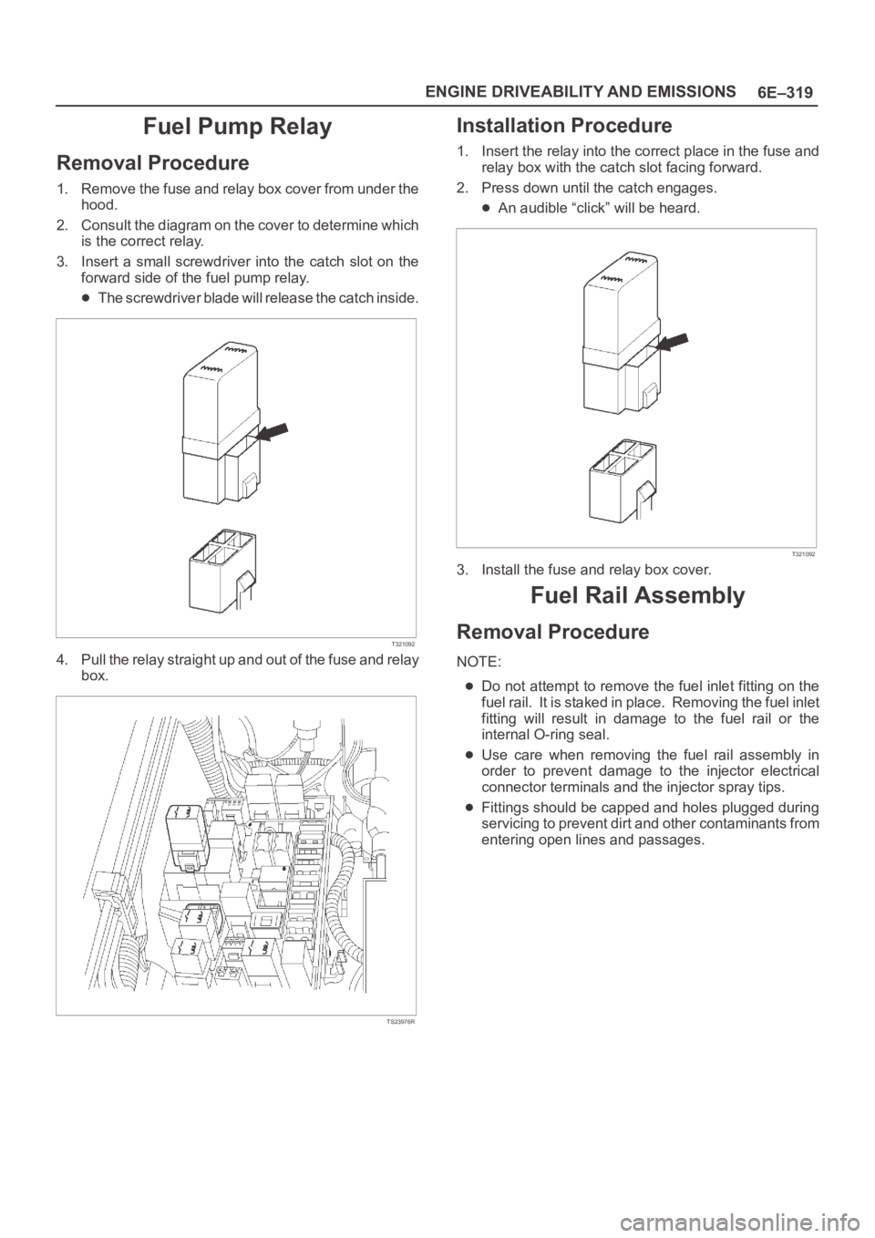
3. Insert a small screwdriver into the catch slot on the
forward side of the fuel pump relay.
The screwdriver blade will release the catch inside.
T321092
4. Pull the relay straight up and out of the fuse and relay
box.
TS23976R
Installation Procedure
1. Insert the relay into the correct place in the fuse and
relay box with the catch slot facing forward.
2. Press down until the catch engages.
An audible “click” will be heard.
T321092
3. Install the fuse and relay box cover.
Fuel Rail Assembly
Removal Procedure
NOTE:
Do not attempt to remove the fuel inlet fitting on the
fuel rail. It is staked in place. Removing the fuel inlet
fitting will result in damage to the fuel rail or the
internal O-ring seal.
Use care when removing the fuel rail assembly in
order to prevent damage to the injector electrical
connector terminals and the injector spray tips.
Fittings should be capped and holes plugged during
servicing to prevent dirt and other contaminants from
entering open lines and passages.
Page 4982 of 6000
6E–325 ENGINE DRIVEABILITY AND EMISSIONS
Spark Plug Gap Check
Check the gap of all spark plugs before installation.
Use a round wire feeler gauge to ensure an accurate
check.
Plugs installed with the wrong gap can cause poor
engine performance and excessive emissions.
Installation Procedure
NOTE: The plug must thread smoothly into the cylinder
head and be fully seated. Use a thread chaser if
necessary to clean the threads in the cylinder head.
Cross-threading or failure to fully seat the spark plug can
cause plug overheating, exhaust blow-by gas, or thread
damage. Do not overtighten the spark plugs. Over
tightening can cause aluminum threads to strip.
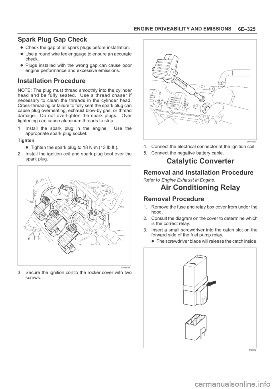
1. Install the spark plug in the engine. Use the
appropriate spark plug socket.
Tighten
Tighten the spark plug to 18 Nꞏm (13 lb ft.).
2. Install the ignition coil and spark plug boot over the
spark plug.
014RW108
3. Secure the ignition coil to the rocker cover with two
screws.
014RW091
4. Connect the electrical connector at the ignition coil.
5. Connect the negative battery cable.
Catalytic Converter
Removal and Installation Procedure
Refer to Engine Exhaust in Engine.
Air Conditioning Relay
Removal Procedure
1. Remove the fuse and relay box cover from under the
hood.
2. Consult the diagram on the cover to determine which
is the correct relay.
3. Insert a small screwdriver into the catch slot on the
forward side of the fuel pump relay.
The screwdriver blade will release the catch inside.
T321092
Page 4983 of 6000
6E–326
ENGINE DRIVEABILITY AND EMISSIONS
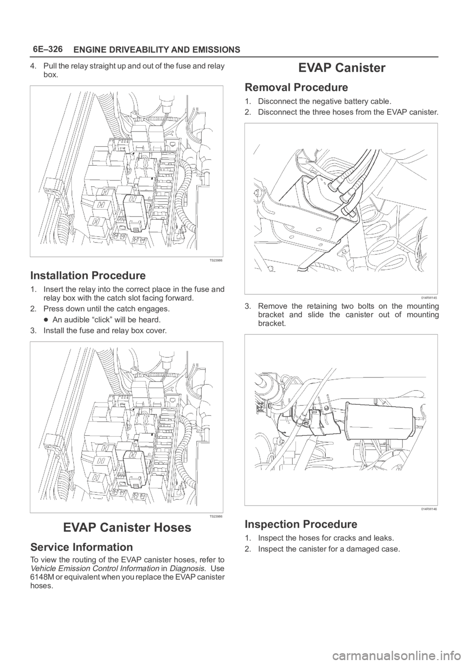
4. Pull the relay straight up and out of the fuse and relay
box.
TS23986
Installation Procedure
1. Insert the relay into the correct place in the fuse and
relay box with the catch slot facing forward.
2. Press down until the catch engages.
An audible “click” will be heard.
3. Install the fuse and relay box cover.
TS23986
EVAP Canister Hoses
Service Information
To view the routing of the EVAP canister hoses, refer to
Vehicle Emission Control Information in Diagnosis. Use
6148M or equivalent when you replace the EVAP canister
hoses.
EVAP Canister
Removal Procedure
1. Disconnect the negative battery cable.
2. Disconnect the three hoses from the EVAP canister.
014RW145
3. Remove the retaining two bolts on the mounting
bracket and slide the canister out of mounting
bracket.
014RW146
Inspection Procedure
1. Inspect the hoses for cracks and leaks.
2. Inspect the canister for a damaged case.
Page 4995 of 6000
6E–338
ENGINE DRIVEABILITY AND EMISSIONS
RPM. A failure in the MAF sensor or circuit will set DTC
P0101, DTC P0102, or DTC P0103.
0007
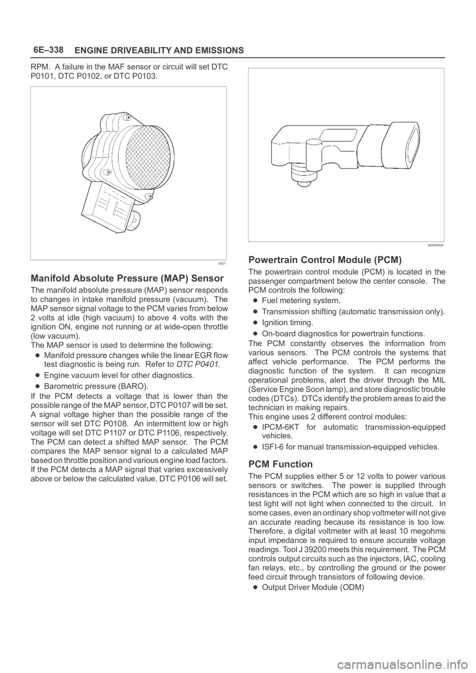
Manifold Absolute Pressure (MAP) Sensor
The manifold absolute pressure (MAP) sensor responds
to changes in intake manifold pressure (vacuum). The
MAP sensor signal voltage to the PCM varies from below
2 volts at idle (high vacuum) to above 4 volts with the
ignition ON, engine not running or at wide-open throttle
(low vacuum).
The MAP sensor is used to determine the following:
Manifold pressure changes while the linear EGR flow
test diagnostic is being run. Refer to
DTC P0401.
Engine vacuum level for other diagnostics.
Barometric pressure (BARO).
If the PCM detects a voltage that is lower than the
possible range of the MAP sensor, DTC P0107 will be set.
A signal voltage higher than the possible range of the
sensor will set DTC P0108. An intermittent low or high
voltage will set DTC P1107 or DTC P1106, respectively.
The PCM can detect a shifted MAP sensor. The PCM
compares the MAP sensor signal to a calculated MAP
based on throttle position and various engine load factors.
If the PCM detects a MAP signal that varies excessively
above or below the calculated value, DTC P0106 will set.
055RW004
Powertrain Control Module (PCM)
The powertrain control module (PCM) is located in the
passenger compartment below the center console. The
PCM controls the following:
Fuel metering system.
Transmission shifting (automatic transmission only).
Ignition timing.
On-board diagnostics for powertrain functions.
The PCM constantly observes the information from
various sensors. The PCM controls the systems that
affect vehicle performance. The PCM performs the
diagnostic function of the system. It can recognize
operational problems, alert the driver through the MIL
(Service Engine Soon lamp), and store diagnostic trouble
codes (DTCs). DTCs identify the problem areas to aid the
technician in making repairs.
This engine uses 2 different control modules:
IPCM-6KT for automatic transmission-equipped
vehicles.
ISFI-6 for manual transmission-equipped vehicles.
PCM Function
The PCM supplies either 5 or 12 volts to power various
sensors or switches. The power is supplied through
resistances in the PCM which are so high in value that a
test light will not light when connected to the circuit. In
some cases, even an ordinary shop voltmeter will not give
an accurate reading because its resistance is too low.
Therefore, a digital voltmeter with at least 10 megohms
input impedance is required to ensure accurate voltage
readings. Tool J 39200 meets this requirement. The PCM
controls output circuits such as the injectors, IAC, cooling
fan relays, etc., by controlling the ground or the power
feed circuit through transistors of following device.
Output Driver Module (ODM)