engine OPEL FRONTERA 1998 Owner's Guide
[x] Cancel search | Manufacturer: OPEL, Model Year: 1998, Model line: FRONTERA, Model: OPEL FRONTERA 1998Pages: 6000, PDF Size: 97 MB
Page 597 of 6000
DRIVE LINE CONTROL SYSTEM (TOD) 4B2–26
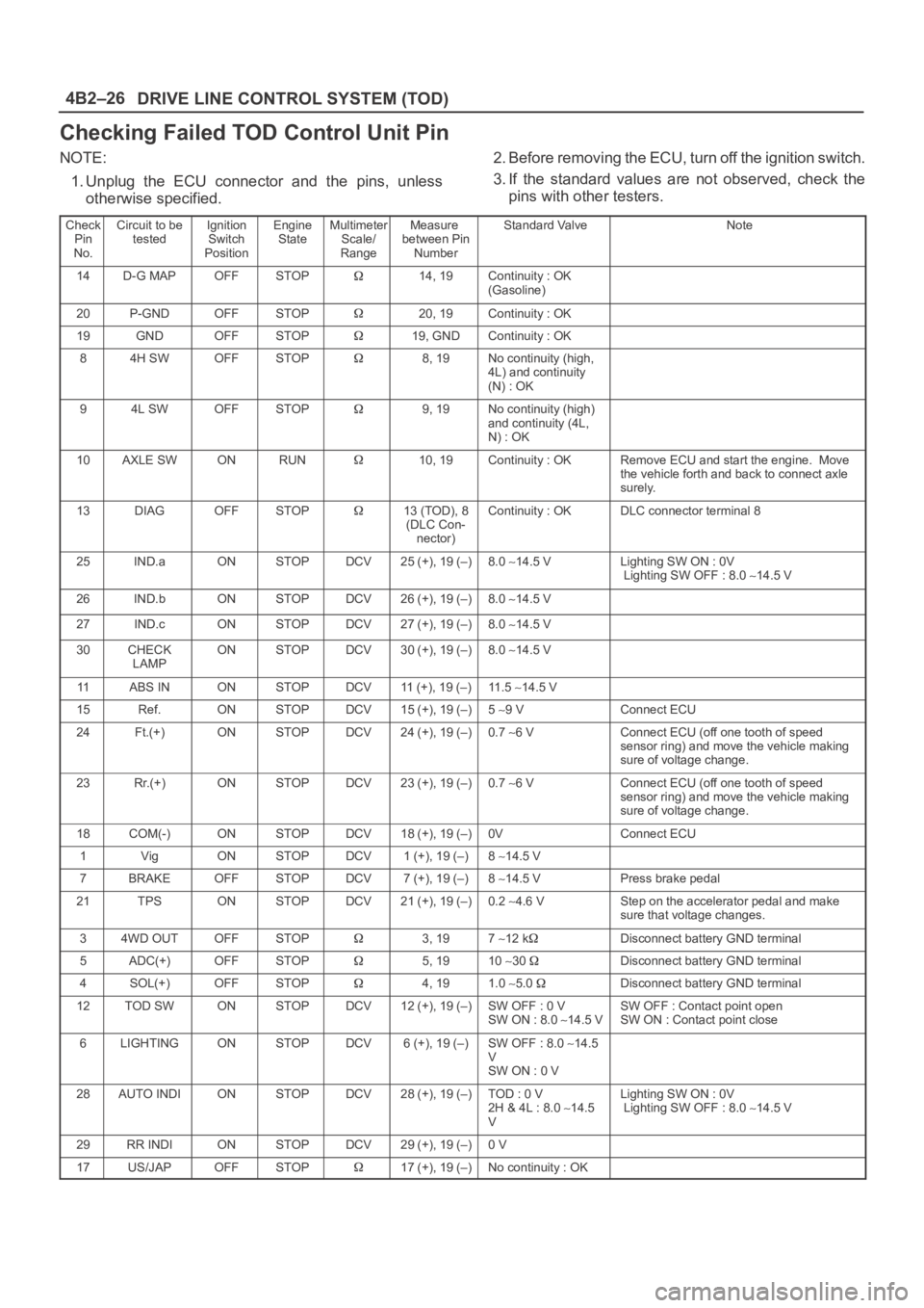
Checking Failed TOD Control Unit Pin
NOTE:
1. Unplug the ECU connector and the pins, unless
otherwise specified.2. Before removing the ECU, turn off the ignition switch.
3. If the standard values are not observed, check the
pins with other testers.
Check
Pin
No.Circuit to be
testedIgnition
Switch
PositionEngine
StateMultimeter
Scale/
RangeMeasure
between Pin
NumberStandard ValveNote
14D-G MAPOFFSTOP14, 19Continuity : OK
(Gasoline)
20P-GNDOFFSTOP20, 19Continuity : OK
19GNDOFFSTOP19, GNDContinuity : OK
84H SWOFFSTOP8, 19No continuity (high,
4L) and continuity
(N) : OK
94L SWOFFSTOP9, 19No continuity (high)
and continuity (4L,
N) : OK
10AXLE SWONRUN10, 19Continuity : OKRemove ECU and start the engine. Move
the vehicle forth and back to connect axle
surely.
13DIAGOFFSTOP13 (TOD), 8
(DLC Con-
nector)Continuity : OKDLC connector terminal 8
25IND.aONSTOPDCV25 (+), 19 (–)8.0 14.5 VLighting SW ON : 0V
Lighting SW OFF : 8.0 14.5 V
26IND.bONSTOPDCV26 (+), 19 (–)8.0 14.5 V
27IND.cONSTOPDCV27 (+), 19 (–)8.0 14.5 V
30CHECK
LAMPONSTOPDCV30 (+), 19 (–)8.0 14.5 V
11ABS INONSTOPDCV11 (+), 19 (–)11 . 5 14.5 V
15Ref.ONSTOPDCV15 (+), 19 (–)5 9 VConnect ECU
24Ft.(+)ONSTOPDCV24 (+), 19 (–)0.7 6 VConnect ECU (off one tooth of speed
sensor ring) and move the vehicle making
sure of voltage change.
23Rr.(+)ONSTOPDCV23 (+), 19 (–)0.7 6 VConnect ECU (off one tooth of speed
sensor ring) and move the vehicle making
sure of voltage change.
18COM(-)ONSTOPDCV18 (+), 19 (–)0VConnect ECU
1VigONSTOPDCV1 (+), 19 (–)8 14.5 V
7BRAKEOFFSTOPDCV7 (+), 19 (–)8 14.5 VPress brake pedal
21TPSONSTOPDCV21 (+), 19 (–)0.2 4.6 VStep on the accelerator pedal and make
sure that voltage changes.
34WD OUTOFFSTOP3, 197 12 kDisconnect battery GND terminal
5ADC(+)OFFSTOP5, 1910 30 Disconnect battery GND terminal
4SOL(+)OFFSTOP4, 191.0 5.0 Disconnect battery GND terminal
12TOD SWONSTOPDCV12 (+), 19 (–)SW OFF : 0 V
SW ON : 8.0 14.5 VSW OFF : Contact point open
SW ON : Contact point close
6LIGHTINGONSTOPDCV6 (+), 19 (–)SW OFF : 8.0 14.5
V
SW ON : 0 V
28AUTO INDIONSTOPDCV28 (+), 19 (–)TOD : 0 V
2H & 4L : 8.0 14.5
VLighting SW ON : 0V
Lighting SW OFF : 8.0 14.5 V
29RR INDIONSTOPDCV29 (+), 19 (–)0 V
17US/JAPOFFSTOP17 (+), 19 (–)No continuity : OK
Page 601 of 6000
DRIVE LINE CONTROL SYSTEM (TOD) 4B2–30
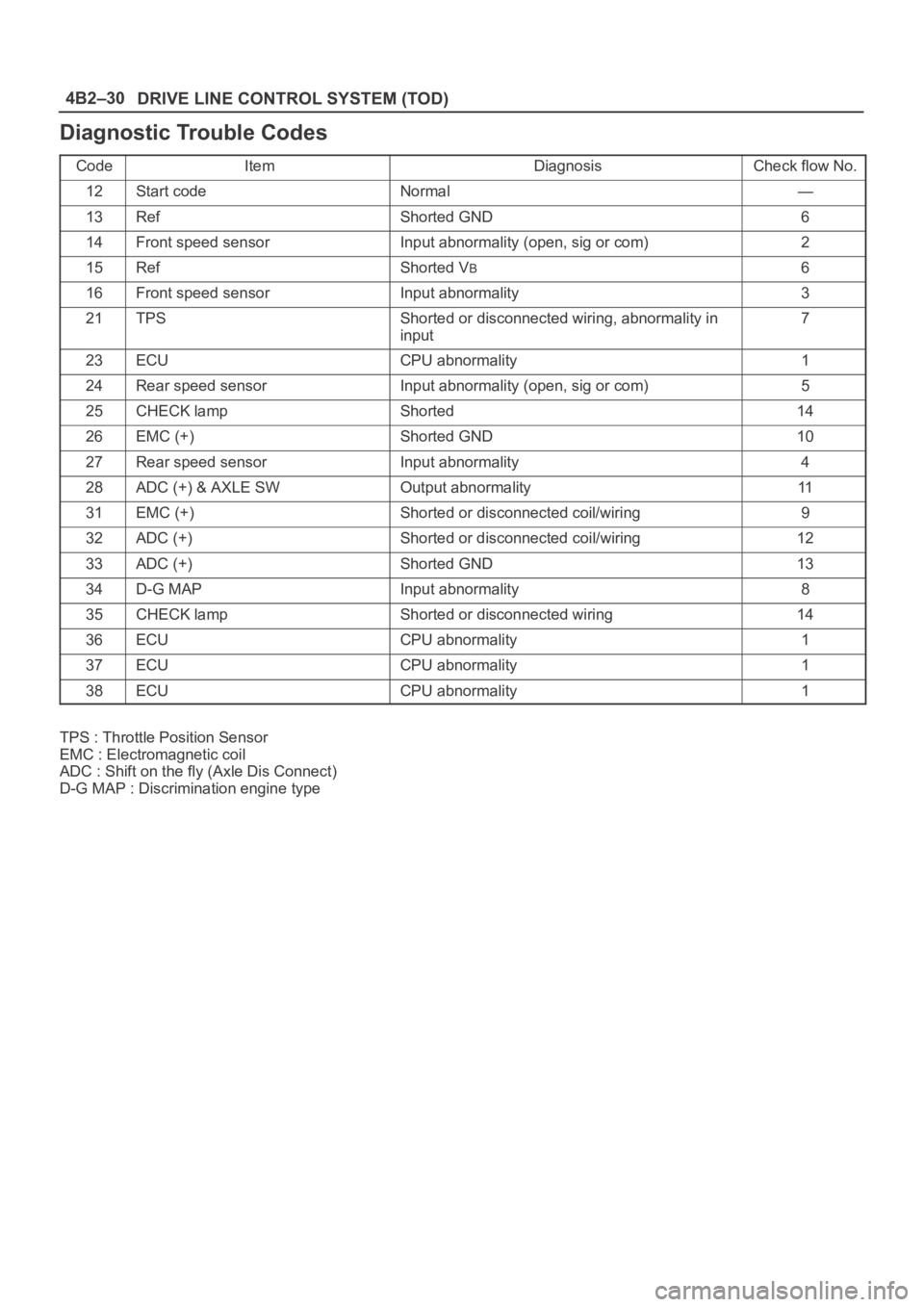
Diagnostic Trouble Codes
CodeItemDiagnosisCheck flow No.
12Start codeNormal—
13RefShorted GND6
14Front speed sensorInput abnormality (open, sig or com)2
15RefShorted VB6
16Front speed sensorInput abnormality3
21TPSShorted or disconnected wiring, abnormality in
input7
23ECUCPU abnormality1
24Rear speed sensorInput abnormality (open, sig or com)5
25CHECK lampShorted14
26EMC (+)Shorted GND10
27Rear speed sensorInput abnormality4
28ADC (+) & AXLE SWOutput abnormality11
31EMC (+)Shorted or disconnected coil/wiring9
32ADC (+)Shorted or disconnected coil/wiring12
33ADC (+)Shorted GND13
34D-G MAPInput abnormality8
35CHECK lampShorted or disconnected wiring14
36ECUCPU abnormality1
37ECUCPU abnormality1
38ECUCPU abnormality1
TPS : Throttle Position Sensor
EMC : Electromagnetic coil
ADC : Shift on the fly (Axle Dis Connect)
D-G MAP : Discrimination engine type
Page 604 of 6000

4B2–33 DRIVE LINE CONTROL SYSTEM (TOD)
StepActionYe sNo
11. Start the engine.
2. Select 4H (TOD) mode.
Is the memory except DTC 14?
Go to Step 3Go to Step 2
2Is the continuity harness of terminal 24 (vehicle side terminal of
the front speed sensor)?Replace speed
sensor.
Go to Step 6
Repair the circuit.
Go to Step 6
3Is the memory DTC 24?
Go to Step 4
Refer to other
trouble check
flow.
Go to Step 2
4Is the continuity between harness of terminal 23 and 24 (vehicle
side terminal of the front and rear speed sensor)?
Go to Step 5
Repair the circuit.
Go to Step 6
5Is the continuity between harness of terminal 18 and 15 (vehicle
side terminal of the speed sensor COM and ref)?Replace front and
rear speed
sensor.
Go to Step 6
Repair the circuit.
Go to Step 6
61. Check that all the parts are mounted.
2. Clear the trouble code.
Is the step complete?
Repeat the
“Diagnosis Flow”.
The trouble is not
reproduced.
Refer to
“Troubles
intermittently
observed”.
Return to Step 6
Page 610 of 6000

4B2–39 DRIVE LINE CONTROL SYSTEM (TOD)
StepActionYe sNo
11. Start the engine.
2. Select 4H (TOD) mode.
Is the memory except DTC 24?
Go to Step 3Go to Step 2
2Is the continuity harness of terminal 23 (vehicle side terminal of
the rear speed sensor)?Replace speed
sensor.
Go to Step 6
Repair the circuit.
Go to Step 6
3Is the memory DTC 14?
Go to Step 4
Refer to other
trouble cheek
flow.
Go to Step 2
4Is the continuity between harness of terminal 23 and 24 (vehicle
side terminal of the front and rear speed sensor)?
Go to Step 5
Repair the circuit
Go to Step 6
5Is the continuity between harness of terminal 15 and 18 (vehicle
side terminal of the speed sensor COM and ref)?Replace front and
rear speed
sensor.
Go to Step 6
Repair the circuit.
Go to Step 6
61. Check that all the parts are mounted.
2. Clear the trouble code.
Is the step complete?
Repeat the
“Diagnosis Flow”.
The trouble is not
reproduced.
Refer to
“Troubles
intermittently
observed”.
Return to Step 6
Page 612 of 6000
4B2–41 DRIVE LINE CONTROL SYSTEM (TOD)
StepActionYe sNo
11. Start the engine.
Does the voltage between terminals 15 and 19 meet the standard
5V?
Go to Step 8Go to Step 2
2Is the voltage below the standard?Go to Step 3Go to Step 7
31. Turn off the starter switch.
2. Disconnect the ECU connector.
Is the continuity established between vehicle harness terminals
(B–67)7 and (B–67)11?
Go to Step 4
The ECU is
failed. Replace
the ECU.
Go to Step 8
41. Disconnect the H-49 connector.
Is the continuity established between floor harness connector
terminals (H-49)3 and (H-49)9?
Go to Step 5Go to Step 6
51. Disconnect the A–3 connector.
Is the continuity established between transfer harness connector
terminals (A–3)2 and (A–3)7?
Replace the front
speed sensor.
Go to Step 8
The reference
harness for the
front speed
sensor is
short–circuited to
GND. Repair the
circuit.
Go to Step 8
61. Disconnect the A–3 connector.
Is the continuity established between transfer harness connector
terminals (A–3)1 and (A–3)7?
Replace the rear
speed sensor.
Go to Step 8
The reference
harness for the
rear speed
sensor is
short–circuited to
GND. Repair the
circuit.
Go to Step 8
71. Turn off the starter switch.
2. Disconnect the ECU connector.
3. Turn on the starter switch.
Is the battery voltage observed between harness connector
terminals (B–67)7 and (B–67)11?
Repair the
harness circuit.
Go to Step 8
The ECU has
failed. Replace
the ECU.
Go to Step 8
81. Check that all the parts are mounted.
2. Clear the trouble code.
Is this step complete?
Repeat the
“Diagnosis Flow”
Go to Step 8
Page 615 of 6000
DRIVE LINE CONTROL SYSTEM (TOD) 4B2–44
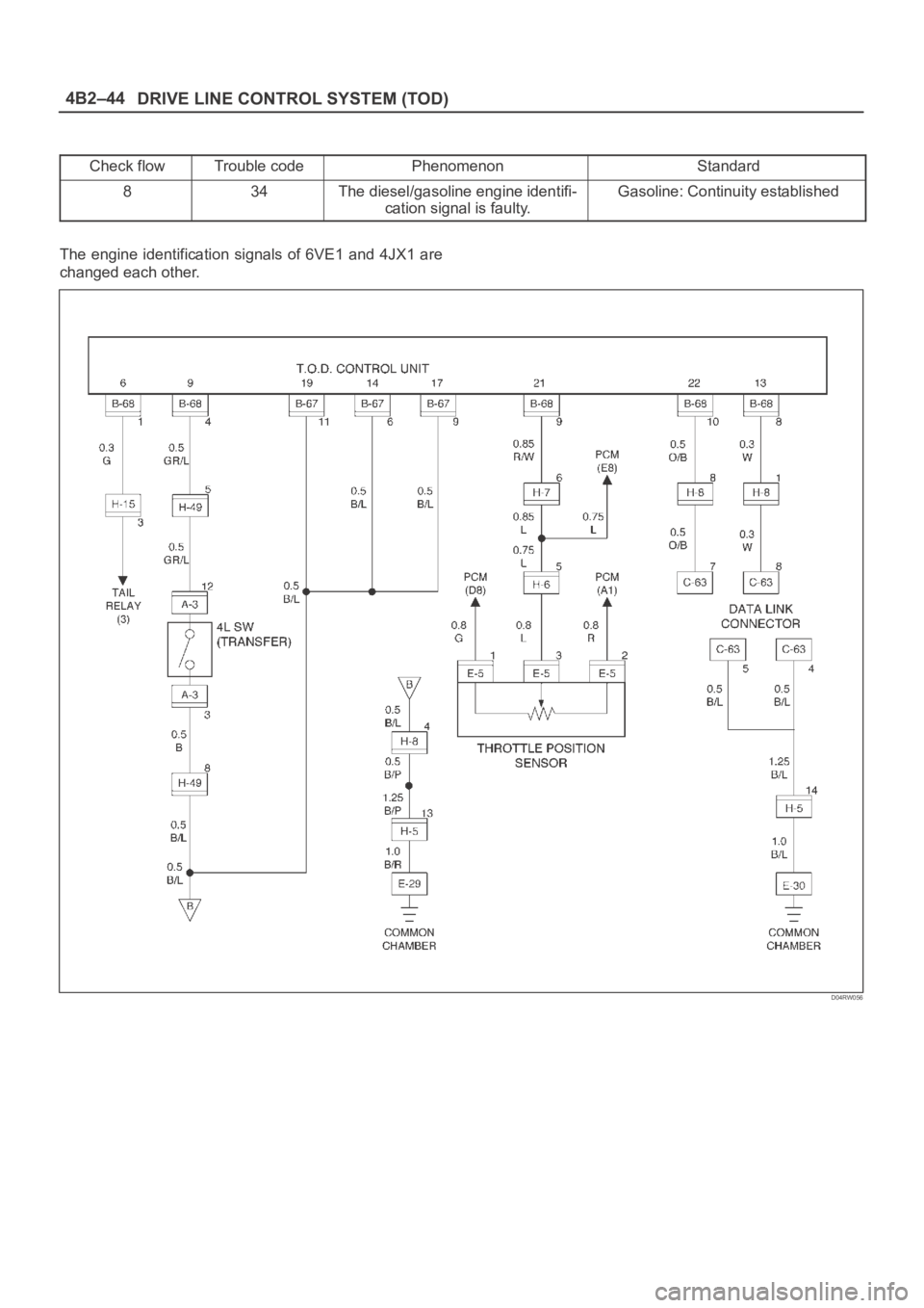
Check flowTrouble codePhenomenonStandard
834The diesel/gasoline engine identifi-
cation signal is faulty.Gasoline: Continuity established
The engine identification signals of 6VE1 and 4JX1 are
changed each other.
D04RW056
Page 618 of 6000
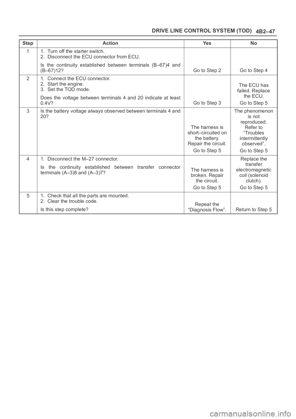
4B2–47 DRIVE LINE CONTROL SYSTEM (TOD)
StepActionYe sNo
11. Turn off the starter switch.
2. Disconnect the ECU connector from ECU.
Is the continuity established between terminals (B–67)4 and
(B–67)12?
Go to Step 2Go to Step 4
21. Connect the ECU connector.
2. Start the engine.
3. Set the TOD mode.
Does the voltage between terminals 4 and 20 indicate at least
0.4V?
Go to Step 3
The ECU has
failed. Replace
the ECU.
Go to Step 5
3Is the battery voltage always observed between terminals 4 and
20?
The harness is
short–circuited on
the battery.
Repair the circuit.
Go to Step 5
The phenomenon
is not
reproduced.
Refer to
“Troubles
intermittently
observed”.
Go to Step 5
41. Disconnect the M–27 connector.
Is the continuity established between transfer connector
terminals (A–3)8 and (A–3)7?
The harness is
broken. Repair
the circuit.
Go to Step 5
Replace the
transfer
electromagnetic
coil (solenoid
clutch).
Go to Step 5
51. Check that all the parts are mounted.
2. Clear the trouble code.
Is this step complete?
Repeat the
“Diagnosis Flow”.
Return to Step 5
Page 620 of 6000
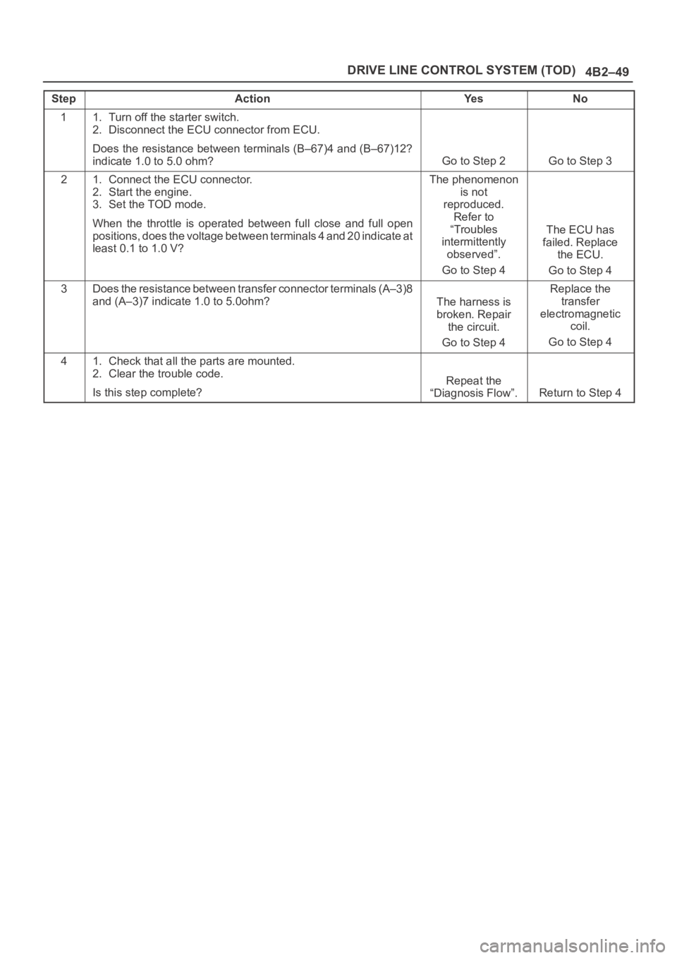
4B2–49 DRIVE LINE CONTROL SYSTEM (TOD)
StepActionYe sNo
11. Turn off the starter switch.
2. Disconnect the ECU connector from ECU.
Does the resistance between terminals (B–67)4 and (B–67)12?
indicate 1.0 to 5.0 ohm?
Go to Step 2Go to Step 3
21. Connect the ECU connector.
2. Start the engine.
3. Set the TOD mode.
When the throttle is operated between full close and full open
positions, does the voltage between terminals 4 and 20 indicate a t
least 0.1 to 1.0 V?The phenomenon
is not
reproduced.
Refer to
“Troubles
intermittently
observed”.
Go to Step 4
The ECU has
failed. Replace
the ECU.
Go to Step 4
3Does the resistance between transfer connector terminals (A–3)8
and (A–3)7 indicate 1.0 to 5.0ohm?
The harness is
broken. Repair
the circuit.
Go to Step 4
Replace the
transfer
electromagnetic
coil.
Go to Step 4
41. Check that all the parts are mounted.
2. Clear the trouble code.
Is this step complete?
Repeat the
“Diagnosis Flow”.
Return to Step 4
Page 648 of 6000
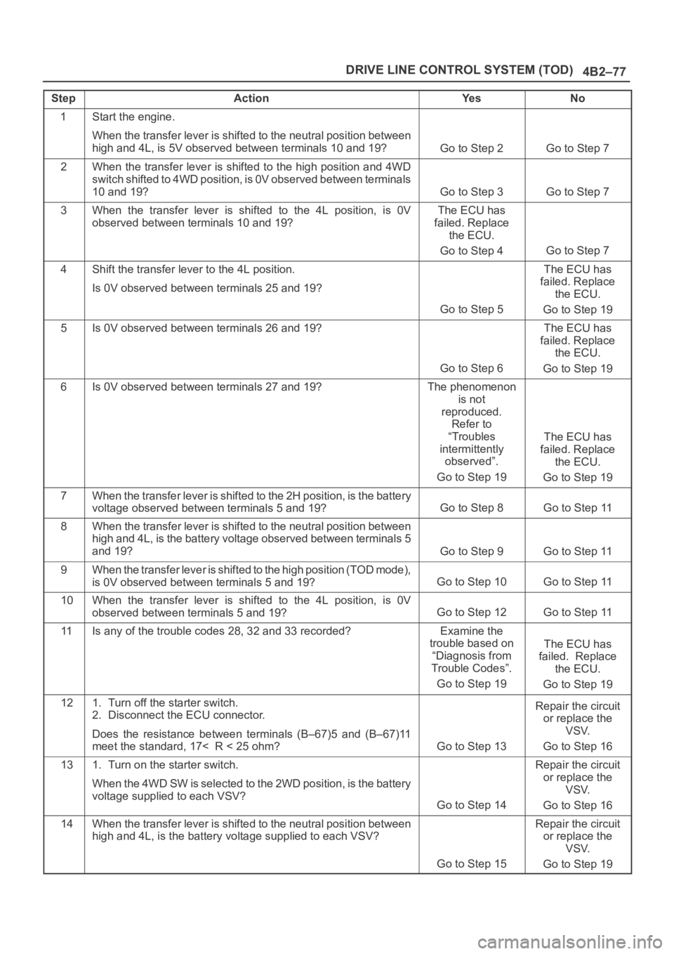
4B2–77 DRIVE LINE CONTROL SYSTEM (TOD)
StepActionYe sNo
1Start the engine.
When the transfer lever is shifted to the neutral position between
high and 4L, is 5V observed between terminals 10 and 19?
Go to Step 2Go to Step 7
2When the transfer lever is shifted to the high position and 4WD
switch shifted to 4WD position, is 0V observed between terminals
10 and 19?
Go to Step 3Go to Step 7
3When the transfer lever is shifted to the 4L position, is 0V
observed between terminals 10 and 19?The ECU has
failed. Replace
the ECU.
Go to Step 4
Go to Step 7
4Shift the transfer lever to the 4L position.
Is 0V observed between terminals 25 and 19?
Go to Step 5
The ECU has
failed. Replace
the ECU.
Go to Step 19
5Is 0V observed between terminals 26 and 19?
Go to Step 6
The ECU has
failed. Replace
the ECU.
Go to Step 19
6Is 0V observed between terminals 27 and 19?The phenomenon
is not
reproduced.
Refer to
“Troubles
intermittently
observed”.
Go to Step 19
The ECU has
failed. Replace
the ECU.
Go to Step 19
7When the transfer lever is shifted to the 2H position, is the battery
voltage observed between terminals 5 and 19?
Go to Step 8Go to Step 11
8When the transfer lever is shifted to the neutral position between
high and 4L, is the battery voltage observed between terminals 5
and 19?
Go to Step 9Go to Step 11
9When the transfer lever is shifted to the high position (TOD mode),
is 0V observed between terminals 5 and 19?
Go to Step 10Go to Step 11
10When the transfer lever is shifted to the 4L position, is 0V
observed between terminals 5 and 19?
Go to Step 12Go to Step 11
11Is any of the trouble codes 28, 32 and 33 recorded?Examine the
trouble based on
“Diagnosis from
Trouble Codes”.
Go to Step 19
The ECU has
failed. Replace
the ECU.
Go to Step 19
121. Turn off the starter switch.
2. Disconnect the ECU connector.
Does the resistance between terminals (B–67)5 and (B–67)11
meet the standard, 17< R < 25 ohm?
Go to Step 13
Repair the circuit
or replace the
VSV.
Go to Step 16
131. Turn on the starter switch.
When the 4WD SW is selected to the 2WD position, is the battery
voltage supplied to each VSV?
Go to Step 14
Repair the circuit
or replace the
VSV.
Go to Step 16
14When the transfer lever is shifted to the neutral position between
high and 4L, is the battery voltage supplied to each VSV?
Go to Step 15
Repair the circuit
or replace the
VSV.
Go to Step 19
Page 651 of 6000

DRIVE LINE CONTROL SYSTEM (TOD) 4B2–80
StepActionYe sNo
1Start the engine.
When the transfer lever is shifted to the neutral position between
high and 4L, is 5V observed between terminals 10 and 19?
Go to Step 2Go to Step 7
2When the transfer lever is shifted to the high position and 4WD
switch shifted to 4WD position, is 0V observed between terminals
10 and 19?
Go to Step 3Go to Step 7
3When the transfer lever is shifted to the 4L position, is 0V
observed between terminals 10 and 19?
Go to Step 4Go to Step 7
4Select the 4WD SW to the 2WD position.
Is 12V observed between terminals 25 and 19?
Go to Step 5Go to Step 19
5Is 12V observed between terminals 26 and 19?Go to Step 6Go to Step 19
6Is 12V observed between terminals 27 and 19?The phenomenon
is not
reproduced.
Refer to
“Troubles
intermittently
observed”.
Go to Step 19
The ECU has
failed. Replace
the ECU.
Go to Step 19
7When the 4WD SW is select to the 2WD position, is the battery
voltage observed between terminals 5 and 19?
Go to Step 8Go to Step 11
8When the transfer lever is shifted to the neutral position between
high and 4L, is the battery voltage observed between terminals 5
and 19?
Go to Step 9Go to Step 11
9When the transfer lever is shifted to the high position and 4WD
switch shifted to 4WD position, is 0V observed between terminals
5 and 19?
Go to Step 10Go to Step 11
10When the transfer lever is shifted to the 4L position, is 0V
observed between terminals 5 and 19?
Go to Step 12Go to Step 11
11Is any of the trouble codes 28, 32 and 33 recorded?Examine the
trouble based on
“Diagnosis from
Trouble Codes”.
Go to Step 19
The ECU has
failed. Replace
the ECU.
Go to Step 19
121. Turn off the starter switch.
2. Disconnect the ECU connector.
Does the resistance between terminals (B–67)5 and (B–67)11
meet the standard, 17< R < 25 ohm?
Go to Step 13
Repair the circuit
or replace the
VSV.
Go to Step 19
131. Connect the ECU connector.
2. Turn on the starter switch.
When the 4WD SW is select to the 2WD position, is the battery
voltage supplied to each VSV?
Go to Step 14
Repair the circuit
or replace the
VSV.
Go to Step 19
14When the transfer lever is shifted to the neutral position between
high and 4L, is the battery voltage supplied to each VSV?
Go to Step 15
Repair the circuit
or replace the
VSV.
Go to Step 19
15When the transfer lever is shifted to the high position and 4WD
switch shifted to 4WD position, is 0V observed on each VSV?
Go to Step 16
Repair the circuit
or replace the
VSV.
Go to Step 19