engine oil OPEL FRONTERA 1998 Service Manual
[x] Cancel search | Manufacturer: OPEL, Model Year: 1998, Model line: FRONTERA, Model: OPEL FRONTERA 1998Pages: 6000, PDF Size: 97 MB
Page 999 of 6000
6A–43
ENGINE MECHANICAL
6. Remove oil pump assembly.
Refer to removal procedure for Oil Pump in this
manual.
7. Remove cylinder body side bolts.
8. Remove oil gallery.
9. Remove flywheel.
10. Remove rear oil seal retainer.
Refer to removal procedure for Rear Oil Seal in this
manual.
11. Remove connecting rod caps.
12. Remove crankshaft main bearing caps.
13. Remove crankshaft and main bearings.
Installation
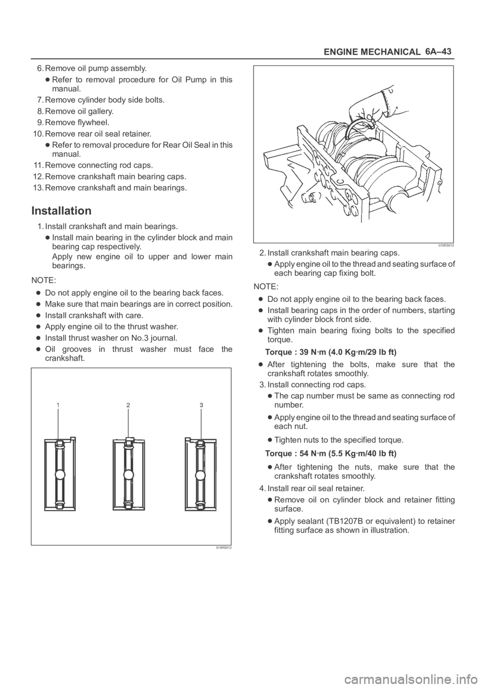
1. Install crankshaft and main bearings.
Install main bearing in the cylinder block and main
bearing cap respectively.
Apply new engine oil to upper and lower main
bearings.
NOTE:
Do not apply engine oil to the bearing back faces.
Make sure that main bearings are in correct position.
Install crankshaft with care.
Apply engine oil to the thrust washer.
Install thrust washer on No.3 journal.
Oil grooves in thrust washer must face the
crankshaft.
015RS012
015RS013
2. Install crankshaft main bearing caps.
Apply engine oil to the thread and seating surface of
each bearing cap fixing bolt.
NOTE:
Do not apply engine oil to the bearing back faces.
Install bearing caps in the order of numbers, starting
with cylinder block front side.
Tighten main bearing fixing bolts to the specified
torque.
Torque : 39 Nꞏm (4.0 Kgꞏm/29 lb ft)
After tightening the bolts, make sure that the
crankshaft rotates smoothly.
3. Install connecting rod caps.
The cap number must be same as connecting rod
number.
Apply engine oil to the thread and seating surface of
each nut.
Tighten nuts to the specified torque.
Torque : 54 Nꞏm (5.5 Kgꞏm/40 lb ft)
After tightening the nuts, make sure that the
crankshaft rotates smoothly.
4. Install rear oil seal retainer.
Remove oil on cylinder block and retainer fitting
surface.
Apply sealant (TB1207B or equivalent) to retainer
fitting surface as shown in illustration.
Page 1000 of 6000

6A–44
ENGINE MECHANICAL
The oil seal retainer must be installed within 5
minutes after sealant application before the sealant
hardens.
015RW002
Legend
(1) Around Bolt Holes
(2) Around Dowel Pin
Apply engine oil to oil seal lip and align a dowel pin
hole in the cylinder block with that in the retainer.
Tighten retainer fixing bolts to the specified torque.
Torque : 18 Nꞏm (1.8 Kgꞏm/13 lb ft)
015RW001
5. Install flywheel.
Clean tapped holes in the crankshaft.
Remove oil on crankshaft and flywheel fitting
surface.
NOTE:
Do not reuse the bolts.
Do not apply oil or thread lock to the bolts.
Tighten fixing bolts to the specified torque.
Torque : 54 Nꞏm (5.5 Kgꞏm/40 lb ft)
015RS018
6. Install oil gallery.
Clean contact surface of oil gallery and main
bearing cap.
Apply engine oil to oil gallery fixing bolts and tighten
the bolts in two steps, in the order shown in
illustration.
To r q u e :
1st step : 29 Nꞏm (3.0 Kgꞏm/21 lb ft)
2nd step : 55
–65
7. Install cylinder body side bolts and tighten bolts in
order to the specified torque.
Torque : 39 Nꞏm (4.0 Kgꞏm/29 lb ft)
NOTE: Do not apply the oil to the bolts.
012RS007
8. Install oil pump assembly.
Remove oil on cylinder block and oil pump mounting
surface.
Page 1001 of 6000
6A–45
ENGINE MECHANICAL
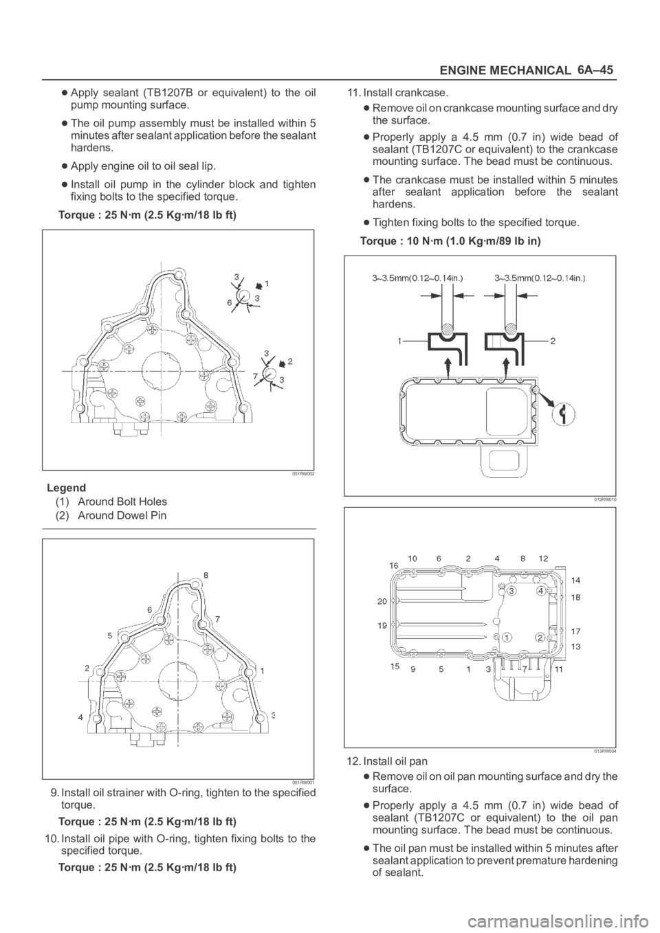
Apply sealant (TB1207B or equivalent) to the oil
pump mounting surface.
The oil pump assembly must be installed within 5
minutes after sealant application before the sealant
hardens.
Apply engine oil to oil seal lip.
Install oil pump in the cylinder block and tighten
fixing bolts to the specified torque.
Torque : 25 Nꞏm (2.5 Kgꞏm/18 lb ft)
051RW002
Legend
(1) Around Bolt Holes
(2) Around Dowel Pin
051RW001
9. Install oil strainer with O-ring, tighten to the specified
torque.
Torque : 25 Nꞏm (2.5 Kgꞏm/18 lb ft)
10. Install oil pipe with O-ring, tighten fixing bolts to the
specified torque.
Torque : 25 Nꞏm (2.5 Kgꞏm/18 lb ft)11. Install crankcase.
Remove oil on crankcase mounting surface and dry
the surface.
Properly apply a 4.5 mm (0.7 in) wide bead of
sealant (TB1207C or equivalent) to the crankcase
mounting surface. The bead must be continuous.
The crankcase must be installed within 5 minutes
after sealant application before the sealant
hardens.
Tighten fixing bolts to the specified torque.
Torque : 10 Nꞏm (1.0 Kgꞏm/89 lb in)
013RW010
013RW004
12. Install oil pan
Remove oil on oil pan mounting surface and dry the
surface.
Properly apply a 4.5 mm (0.7 in) wide bead of
sealant (TB1207C or equivalent) to the oil pan
mounting surface. The bead must be continuous.
The oil pan must be installed within 5 minutes after
sealant application to prevent premature hardening
of sealant.
Page 1003 of 6000
6A–47
ENGINE MECHANICAL
Rear Oil Seal
Removal
1. Remove transmission assembly.
Refer to removal procedure for Transmission
section in this manual.
2. Remove flywheel.
3. Remove rear oil seal using a seal remover.
NOTE: Take care not to damage the crankshaft or oil seal
retainer when removing oil seal.
Installation
1. Apply engine oil to oil seal lip and install oil seal using
5–8840–2286–0.
015RS017
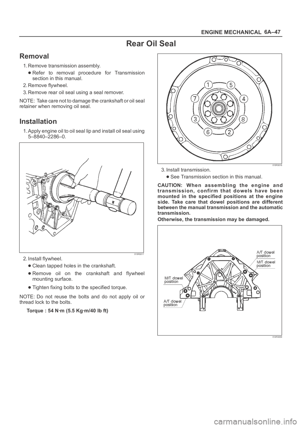
2. Install flywheel.
Clean tapped holes in the crankshaft.
Remove oil on the crankshaft and flywheel
mounting surface.
Tighten fixing bolts to the specified torque.
NOTE: Do not reuse the bolts and do not apply oil or
thread lock to the bolts.
Torque : 54 Nꞏm (5.5 Kgꞏm/40 lb ft)
015RS018
3. Install transmission.
See Transmission section in this manual.
CAUTION: W h e n a s s e m b l i n g t h e e n g i n e a n d
transmission, confirm that dowels have been
mounted in the specified positions at the engine
side. Take care that dowel positions are different
between the manual transmission and the automatic
transmission.
Otherwise, the transmission may be damaged.
012RS009
Page 1006 of 6000
6A–50
ENGINE MECHANICAL
9. Install air conditioner compressor to engine and
tighten to the specified torque.
Torque :
M8 bolts : 22 Nꞏm (2.2 Kgꞏm/16 lb ft)
M10 bolts : 43 Nꞏm (4.4 Kgꞏm/32 lb ft)
10. Install power steering pump, tighten fixing bolt to the
specified torque.
Torque :
M8 bolts : 22Nꞏm (2.2 Kgꞏm/16 lb ft)
M10 bolts : 46 Nꞏm (4.7 Kgꞏm/34 lb ft)
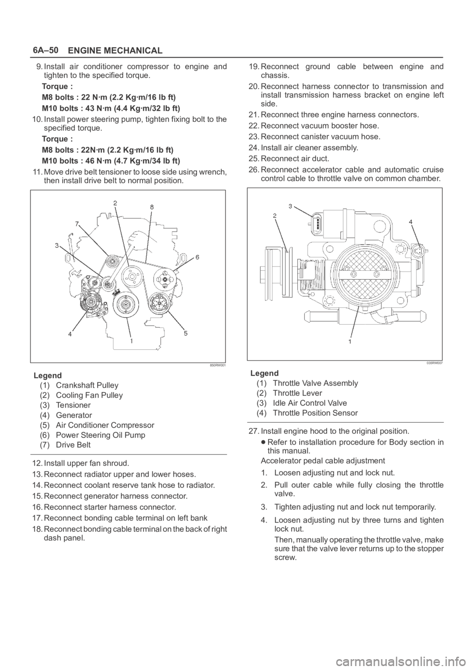
11. Move drive belt tensioner to loose side using wrench,
then install drive belt to normal position.
850RW001
Legend
(1) Crankshaft Pulley
(2) Cooling Fan Pulley
(3) Tensioner
(4) Generator
(5) Air Conditioner Compressor
(6) Power Steering Oil Pump
(7) Drive Belt
12. Install upper fan shroud.
13. Reconnect radiator upper and lower hoses.
14. Reconnect coolant reserve tank hose to radiator.
15. Reconnect generator harness connector.
16. Reconnect starter harness connector.
17. Reconnect bonding cable terminal on left bank
18. Reconnect bonding cable terminal on the back of right
dash panel.19. Reconnect ground cable between engine and
chassis.
20. Reconnect harness connector to transmission and
install transmission harness bracket on engine left
side.
21. Reconnect three engine harness connectors.
22. Reconnect vacuum booster hose.
23. Reconnect canister vacuum hose.
24. Install air cleaner assembly.
25. Reconnect air duct.
26. Reconnect accelerator cable and automatic cruise
control cable to throttle valve on common chamber.
035RW007
Legend
(1) Throttle Valve Assembly
(2) Throttle Lever
(3) Idle Air Control Valve
(4) Throttle Position Sensor
27. Install engine hood to the original position.
Refer to installation procedure for Body section in
this manual.
Accelerator pedal cable adjustment
1. Loosen adjusting nut and lock nut.
2. Pull outer cable while fully closing the throttle
valve.
3. Tighten adjusting nut and lock nut temporarily.
4. Loosen adjusting nut by three turns and tighten
lock nut.
Then, manually operating the throttle valve, make
s u r e t h a t t h e v a l v e l e v e r r e t u r n s u p t o t h e s t o p p e r
screw.
Page 1010 of 6000

6A–54
ENGINE MECHANICAL
2. Tighten the M5 bolt to a suitable torque to prevent
the sub gear from moving .
014RW025
3. Install camshaft drive gear assembly and tighten
three bolts to the specified torque.
Torque: 10 Nꞏm (1.0 Kgꞏm/89 lb in)
4. Install camshaft assembly and camshaft brackets,
tighten twenty bolts on one side bank to the specified
torque.
1. Apply engine oil to camshaft journal and bearing
surface of camshaft bracket.
2. Align timing mark on intake camshaft (one dot for
right bank, two dots for left bank) and exhaust
camshaft (one dot for right bank, two dots for left
bank) to timing mark on camshaft drive gear (one
dot).
014RW020
Legend
(1) Intake Camshaft Timing Gear for Right Bank
(2) Intake Camshaft Timing Gear for Left Bank
(3) Exhaust Camshaft Timing Gear
(4) Discrimination Mark
LI: Left Bank Intake
RI: Right Bank Intake
LE: Left Bank Exhaust
RE: Right Bank Exhaust
014RW023
Legend
(1) Right Bank Camshaft Drive Gear
(2) Left Bank Camshaft Drive Gear
(3) Timing Mark on Drive Gear
(4) Dowel Pin
Page 1012 of 6000

6A–56
ENGINE MECHANICAL
Valve Spring, Oil Controller, Valve, Valve Guide
Valve Spring, Oil Controller, Valve, Valve Guide and Associated Parts
014RW039
Legend
(1) Camshaft Bracket Fixing Bolts
(2) Camshaft Assembly Inlet
(3) Camshaft Assembly Exhaust
(4) Shim
(5) Tappet
(6) Split Collar(7) Spring Upper Seat
(8) Valve Spring
(9) Oil Controller
(10) Spring Lower Seat
(11) Valve Guide
(12) Valve
Disassembly
1. Remove camshaft bracket fixing bolts (1).
2. Remove camshaft assembly (intake).3. Remove camshaft assembly (Exhaust side).
4. Remove shim (4) and tappet (5).
Page 1013 of 6000
6A–57
ENGINE MECHANICAL
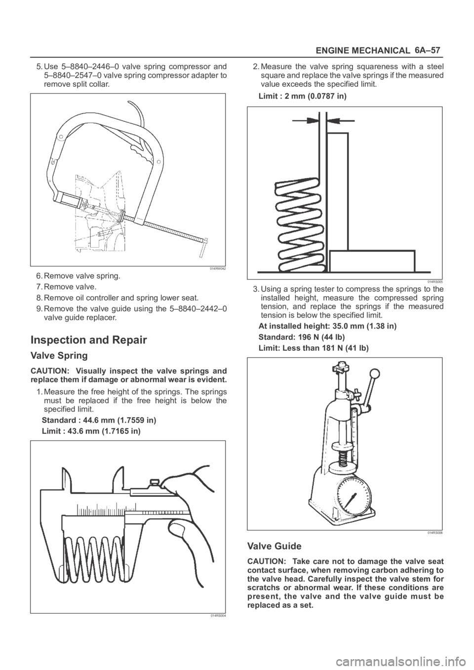
5. Use 5–8840–2446–0 valve spring compressor and
5–8840–2547–0 valve spring compressor adapter to
remove split collar.
014RW042
6. Remove valve spring.
7. Remove valve.
8. Remove oil controller and spring lower seat.
9. Remove the valve guide using the 5–8840–2442–0
valve guide replacer.
Inspection and Repair
Valve Spring
CAUTION: Visually inspect the valve springs and
replace them if damage or abnormal wear is evident.
1. Measure the free height of the springs. The springs
must be replaced if the free height is below the
specified limit.
Standard : 44.6 mm (1.7559 in)
Limit : 43.6 mm (1.7165 in)
014RS004
2. Measure the valve spring squareness with a steel
square and replace the valve springs if the measured
value exceeds the specified limit.
Limit : 2 mm (0.0787 in)
014RS005
3. Using a spring tester to compress the springs to the
installed height, measure the compressed spring
tension, and replace the springs if the measured
tension is below the specified limit.
At installed height: 35.0 mm (1.38 in)
Standard: 196 N (44 lb)
Limit: Less than 181 N (41 lb)
014RS006
Valve Guide
CAUTION: Take care not to damage the valve seat
contact surface, when removing carbon adhering to
the valve head. Carefully inspect the valve stem for
scratchs or abnormal wear. If these conditions are
present, the valve and the valve guide must be
replaced as a set.
Page 1014 of 6000
6A–58
ENGINE MECHANICAL
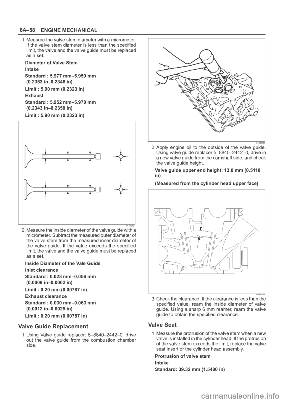
1. Measure the valve stem diameter with a micrometer.
If the valve stem diameter is less than the specified
limit, the valve and the valve guide must be replaced
as a set.
Diameter of Valve Stem
Intake
Standard : 5.977 mm–5.959 mm
(0.2353 in–0.2346 in)
Limit : 5.90 mm (0.2323 in)
Exhaust
Standard : 5.952 mm–5.970 mm
(0.2343 in–0.2350 in)
Limit : 5.90 mm (0.2323 in)
014RS007
2. Measure the inside diameter of the valve guide with a
micrometer. Subtract the measured outer diameter of
the valve stem from the measured inner diameter of
the valve guide. If the value exceeds the specified
limit, the valve and the valve guide must be replaced
as a set.
Inside Diameter of the Vale Guide
Inlet clearance
Standard : 0.023 mm–0.056 mm
(0.0009 in–0.0002 in)
Limit : 0.20 mm (0.00787 in)
Exhaust clearance
Standard : 0.030 mm–0.063 mm
(0.0012 in–0.0025 in)
Limit : 0.20 mm (0.00787 in)
Valve Guide Replacement
1. Using Valve guide replacer: 5–8840–2442–0, drive
out the valve guide from the combustion chamber
side.
014RS008
2. Apply engine oil to the outside of the valve guide.
Using valve guide replacer 5–8840–2442–0, drive in
a new valve guide from the camshaft side, and check
the valve guide height.
Valve guide upper end height: 13.0 mm (0.5118
in)
(Measured from the cylinder head upper face)
014RW046
3. Check the clearance. If the clearance is less than the
specified value, ream the inside diameter of valve
guide. Using a sharp 6 mm reamer, ream the valve
guide to obtain the specified clearance.
Va l v e S e a t
1. Measure the protrusion of the valve stem when a new
valve is installed in the cylinder head. If the protrusion
of the valve stem exceeds the limit, replace the valve
seat insert or the cylinder head assembly.
Protrusion of valve stem
Intake
Standard: 39.32 mm (1.5480 in)
Page 1016 of 6000
6A–60
ENGINE MECHANICAL
6. Check that the valve contact width is correct.
7. Check that the valve seat insert surface is in contact
with the entire circumference of the valve.
014RS014
Valve Seat Insert Replacement
1. Arc weld the rod at several points. Be careful not to
damage the aluminum section.
2. Allow the rod to cool for a few minutes. This will cause
the valve seat to shrink.
3. Strike the rod and pull it out.
014RS015
4. Carefully clean the valve seat press–fit section on the
cylinder head side.
5. Heat the press–fit section with steam or some other
means to cause expansion. Cool the valve seat with
dry ice or some other means.
6. Insert the press–fit section into the valve seat
horizontally.
Standard fitting interference: 0.14 mm–0.09 mm
(0.0055 in–0.0035 in)7. After insertion, use a seat grinder to grind finish the
seating face. Carefully note the seating angle, the
contact width, and the depression.
8. Lap the valve and the seat.
Reassembly
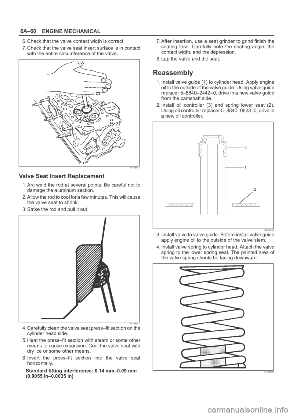
1. Install valve guide (1) to cylinder head. Apply engine
oil to the outside of the valve guide. Using valve guide
replacer 5–8840–2442–0, drive in a new valve guide
from the camshaft side.
2. Install oil controller (3) and spring lower seat (2).
Using oil controller replacer 5–8840–0623–0, drive in
a new oil controller.
014RW058
3. Install valve to valve guide. Before install valve guide
apply engine oil to the outside of the valve stem.
4. Install valve spring to cylinder head. Attach the valve
spring to the lower spring seat. The painted area of
the valve spring should be facing downward.
014RS020