wiring OPEL FRONTERA 1998 Workshop Manual
[x] Cancel search | Manufacturer: OPEL, Model Year: 1998, Model line: FRONTERA, Model: OPEL FRONTERA 1998Pages: 6000, PDF Size: 97 MB
Page 5020 of 6000
6G–1 ENGINE LUBRICATION
ENGINE
ENGINE LUBRICATION
CONTENTS
Service Precaution 6G–1. . . . . . . . . . . . . . . . . . . . . .
General Description 6G–2. . . . . . . . . . . . . . . . . . . . .
Oil Pump 6G–3. . . . . . . . . . . . . . . . . . . . . . . . . . . . . . .
Oil Pump and Associated Parts 6G–3. . . . . . . . . .
Oil Pump and Associated Parts 6G–3. . . . . . . . . .
Inspection and Repair 6G–4. . . . . . . . . . . . . . . . . .
Reassembly 6G–5. . . . . . . . . . . . . . . . . . . . . . . . . .
Oil Pan and Crankcase 6G–7. . . . . . . . . . . . . . . . . .
Removal 6G–7. . . . . . . . . . . . . . . . . . . . . . . . . . . . .
Installation 6G–7. . . . . . . . . . . . . . . . . . . . . . . . . . . .
Oil Pump 6G–10. . . . . . . . . . . . . . . . . . . . . . . . . . . . . . . Removal 6G–10. . . . . . . . . . . . . . . . . . . . . . . . . . . . .
Installation 6G–10. . . . . . . . . . . . . . . . . . . . . . . . . . . .
Oil Pump Oil Seal 6G–12. . . . . . . . . . . . . . . . . . . . . . .
Removal 6G–12. . . . . . . . . . . . . . . . . . . . . . . . . . . . .
Installation 6G–12. . . . . . . . . . . . . . . . . . . . . . . . . . . .
Oil Filter 6G–13. . . . . . . . . . . . . . . . . . . . . . . . . . . . . . . .
Removal 6G–13. . . . . . . . . . . . . . . . . . . . . . . . . . . . .
Installation 6G–13. . . . . . . . . . . . . . . . . . . . . . . . . . . .
Main Data and Specification 6G–14. . . . . . . . . . . . . .
Special Tool 6G–15. . . . . . . . . . . . . . . . . . . . . . . . . . . .
Service Precaution
WARNING: IF SO EQUIPPED WITH A
SUPPLEMENTAL RESTRAINT SYSTEM (SRS),
REFER TO THE SRS COMPONENT AND WIRING
LOCATION VIEW IN ORDER TO DETERMINE
WHETHER YOU ARE PERFORMING SERVICE ON OR
NEAR THE SRS COMPONENTS OR THE SRS
WIRING. WHEN YOU ARE PERFORMING SERVICE
ON OR NEAR THE SRS COMPONENTS OR THE SRS
WIRING, REFER TO THE SRS SERVICE
INFORMATION. FAILURE TO FOLLOW WARNINGS
COULD RESULT IN POSSIBLE AIR BAG
DEPLOYMENT, PERSONAL INJURY, OR
OTHERWISE UNNEEDED SRS SYSTEM REPAIRS.
CAUTION: Always use the correct fastener in the
proper location. When you replace a fastener, use
ONLY the exact part number for that application.
ISUZU will call out those fasteners that require a
replacement after removal. ISUZU will also call out
the fasteners that require thread lockers or thread
sealant. UNLESS OTHERWISE SPECIFIED, do not
use supplemental coatings (Paints, greases, or other
corrosion inhibitors) on threaded fasteners or
fastener joint interfaces. Generally, such coatings
adversely affect the fastener torque and the joint
clamping force, and may damage the fastener. When
you install fasteners, use the correct tightening
sequence and specifications. Following these
instructions can help you avoid damage to parts and
systems.
Page 5035 of 6000
6H–1 ENGINE SPEED CONTROL SYSTEM
ENGINE
ENGINE SPEED CONTROL SYSTEM
CONTENTS
Service Precaution 6H–1. . . . . . . . . . . . . . . . . . . . . .
Accelerator Pedal Control Cable 6H–2. . . . . . . . . .
Removal 6H–2. . . . . . . . . . . . . . . . . . . . . . . . . . . . .
Inspection 6H–2. . . . . . . . . . . . . . . . . . . . . . . . . . . .
Installation 6H–2. . . . . . . . . . . . . . . . . . . . . . . . . . . .
Adjustment 6H–2. . . . . . . . . . . . . . . . . . . . . . . . . . . Accelerator Pedal 6H–3. . . . . . . . . . . . . . . . . . . . . . .
Accelerator Pedal and Associated Parts 6H–3. .
Removal 6H–3. . . . . . . . . . . . . . . . . . . . . . . . . . . . .
Installation 6H–3. . . . . . . . . . . . . . . . . . . . . . . . . . . .
Adjustment 6H–3. . . . . . . . . . . . . . . . . . . . . . . . . . .
Service Precaution
WARNING: IF SO EQUIPPED WITH A
SUPPLEMENTAL RESTRAINT SYSTEM (SRS),
REFER TO THE SRS COMPONENT AND WIRING
LOCATION VIEW IN ORDER TO DETERMINE
WHETHER YOU ARE PERFORMING SERVICE ON OR
NEAR THE SRS COMPONENTS OR THE SRS
WIRING. WHEN YOU ARE PERFORMING SERVICE
ON OR NEAR THE SRS COMPONENTS OR THE SRS
WIRING, REFER TO THE SRS SERVICE
INFORMATION. FAILURE TO FOLLOW WARNINGS
COULD RESULT IN POSSIBLE AIR BAG
DEPLOYMENT, PERSONAL INJURY, OR
OTHERWISE UNNEEDED SRS SYSTEM REPAIRS.
CAUTION: Always use the correct fastener in the
proper location. When you replace a fastener, use
ONLY the exact part number for that application.
ISUZU will call out those fasteners that require a
replacement after removal. ISUZU will also call out
the fasteners that require thread lockers or thread
sealant. UNLESS OTHERWISE SPECIFIED, do not
use supplemental coatings (Paints, greases, or other
corrosion inhibitors) on threaded fasteners or
fastener joint interfaces. Generally, such coatings
adversely affect the fastener torque and the joint
clamping force, and may damage the fastener. When
you install fasteners, use the correct tightening
sequence and specifications. Following these
instructions can help you avoid damage to parts and
systems.
Page 5039 of 6000
INDUCTION6J–1
ENGINE
INDUCTION
CONTENTS
Service Precaution 6J–1. . . . . . . . . . . . . . . . . . . . . .
Air Cleaner Element 6J–2. . . . . . . . . . . . . . . . . . . . .
Removal 6J–2. . . . . . . . . . . . . . . . . . . . . . . . . . . . .
Inspection 6J–2. . . . . . . . . . . . . . . . . . . . . . . . . . . .
Installation 6J–2. . . . . . . . . . . . . . . . . . . . . . . . . . . .
Service Precaution
WARNING: IF SO EQUIPPED WITH A
SUPPLEMENTAL RESTRAINT SYSTEM
(SRS),REFER TO THE SRS COMPONENT AND
WIRING LOCATION VIEW IN ORDER TO DETERMINE
WHETHER YOU ARE PERFORMING SERVICE ON OR
NEAR THE SRS COMPONENTS OR THE SRS
WIRING. WHEN YOU ARE PERFORMING SERVICE
ON OR NEAR THE SRS COMPONENTS OR THE SRS
WIRING, REFER TO THE SRS SERVICE
INFORMATION. FAILURE TO FOLLOW WARNINGS
COULD RESULT IN POSSIBLE AIR BAG
DEPLOYMENT, PERSONAL INJURY, OR
OTHERWISE UNNEEDED SRS SYSTEM REPAIRS.
CAUTION: Always use the correct fastener in the
proper location. When you replace a fastener, use
ONLY the exact part number for that application.
ISUZU will call out those fasteners that require a
replacement after removal. ISUZU will also call out
the fasteners that require thread lockers or thread
sealant. UNLESS OTHERWISE SPECIFIED, do not
use supplemental coatings (Paints, greases, or other
corrosion inhibitors) on threaded fasteners or
fastener joint interfaces. Generally, such coatings
adversely affect the fastener torque and the joint
clamping force, and may damage the fastener. When
you install fasteners, use the correct tightening
sequence and specifications. Following these
instructions can help you avoid damage to parts and
systems.
Page 5313 of 6000
6A – 40 ENGINE MECHANICAL
REMOVAL
1. Disconnect battery ground cable.
2. Drain engine coolant.
3. Remove air cleaner and air duct.
4. Remove intercooler assembly.
Refer to “Intercooler” in this manual.
5. Remove oil level gauge guide assembly.
6. Remove PCV hose.
7. Remove EGR vacuum hose.
8. Disconnect harness connector around the cylinder
head.
9. Remove A/C compressor assembly.
10. Remove A/C compressor bracket.
11. Remove generator assembly and take out fan belt.
12. Remove heat protector and remove valve
assembly.
13. Remove water hose and oil pipe from turbocharger.
14. Remove turbocharger assembly.
15. Remove water hose between thermostat and
radiator.
16. Remove cylinder head noise insulator cover.
NOTE: Do not make damage to the harness.
17. Remove high pressure pipe.
18. Remove timing belt cover.
19. Remove CMP sensor bracket.
20. Remove timing belt tensioner and remove timing
belt.
21. Remove camshaft pulley.
22. Remove front plate.
23. Remove water pipe between cylinder head and
water pump.
24. Remove fuel pipe between fuel pump and intake
manifold.
25. Remove fuel return pipe.
26. Remove intake manifold assembly.
27. Disconnect glow plug wiring and remove glow plug.
28. Remove cylinder head cover.
29. Drain oil from oil rail.
30. Disconnect injector harness connector.
31. Disconnect harness connector from oil pressure
sensor and oil temperature sensor on the oil rail.
32. Disconnect injector harness assembly.
33. Remove injector clamp.
34. Remove injector spacer.
35. Remove injector assembly.
36. Remove oil rail assembly.
37. Remove camshaft carrier.
38. Remove cylinder head assembly.
39. Remove cylinder gasket.
INSTALLATION
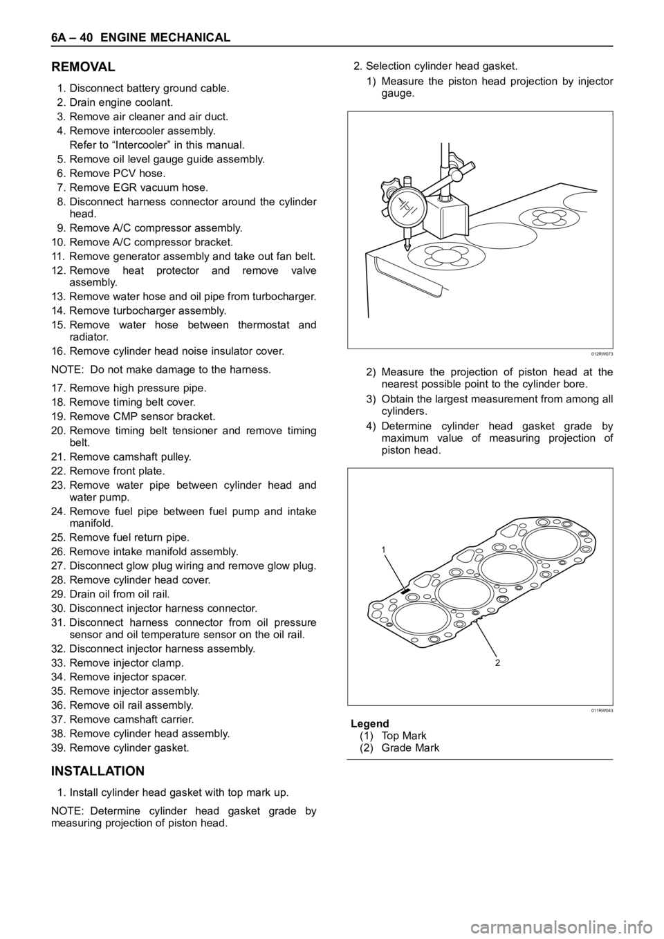
1. Install cylinder head gasket with top mark up.
NOTE: Determine cylinder head gasket grade by
measuring projection of piston head.2. Selection cylinder head gasket.
1) Measure the piston head projection by injector
gauge.
2) Measure the projection of piston head at the
nearest possible point to the cylinder bore.
3) Obtain the largest measurement from among all
cylinders.
4) Determine cylinder head gasket grade by
maximum value of measuring projection of
piston head.
Legend
(1) Top Mark
(2) Grade Mark
012RW073
2 1
011RW043
Page 5410 of 6000

ENGINE ELECTRICAL 6D – 7
ON-VEHICLE SERVICE
STARTER
REMOVAL
1 Battery ground cable
2 Remove the slave cylinder and bind with wire it to
the frame.
3 Disconnect the connector from terminals “B” and
“S”.
4. Remove mounting bolts
5. Remove starter assembly
INSTALLATION
1. Install starter assembly, tighten the fixing bolt and
nut to the specified torque.
Torque: 94 Nꞏm (9.6 kgꞏm/69 lb ft)
2. Reconnect the starter terminals.
CAUTION: When installing the starter motor wiring,
do not allow the S-circuit wiring to obstruct the B-
circuit terminal.
Install the wiring exactly as shown on the attached
illustration.
If S-circuit wiring obstructs the B-circuit terminal,
harness cover breakage and short circuiting may
occur.2-1. Install the wire harness from the battery to the
terminal “B” with tightening torque 8.6 Nꞏm
(0.88 kgꞏm/6.4 lbꞏft).
2-2. Cover the terminal “B” together with wire
harness.
2-3. Connect the wire harness from starter relay to
the terminal “S”.
3. Install the clutch slave cylinder, tighten the fixing
bolt and nut to the specified torque.
Torque: 78 Nꞏm (8.0 kgꞏm/58 lbꞏft)
1
32
4
Legend
(1) Clutch Slave Cylinder
(2) Magnetic Switch(3) Bolt
(4) Starter Assembly
065RW00003
Do not recommend
wiring route.
Recommend wiring route
from S terminal.From
battery
From
starter relay Terminal B
Terminal MTerminal SIn this area,
Scratch to break the wire
cover and make shortage.
065RW00002
Page 5419 of 6000
6D – 16 ENGINE ELECTRICAL
DIAGNOSIS
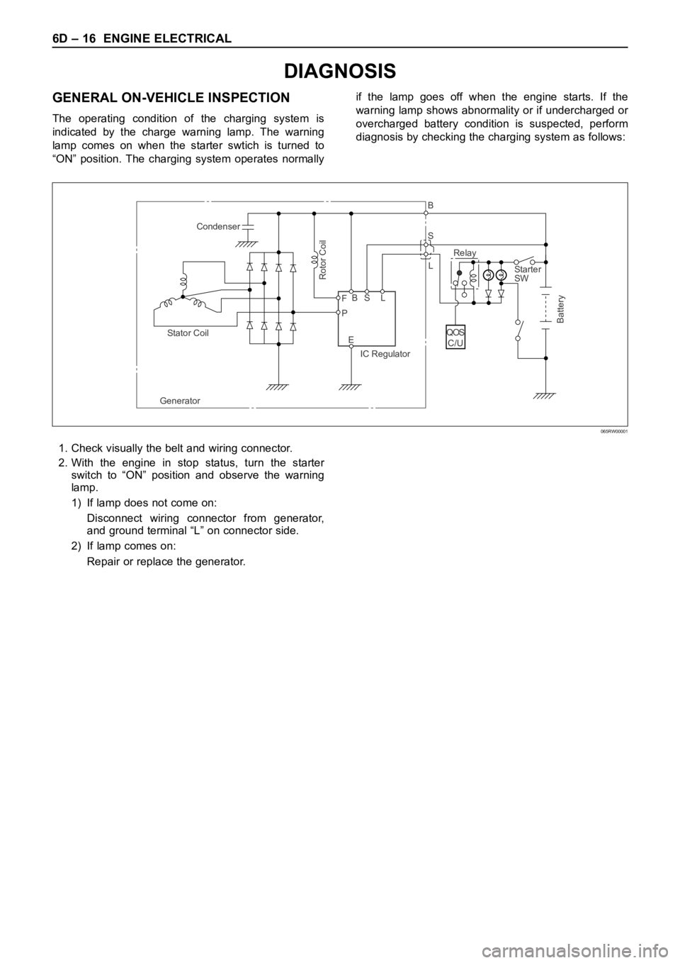
GENERAL ON-VEHICLE INSPECTION
The operating condition of the charging system is
indicated by the charge warning lamp. The warning
lamp comes on when the starter swtich is turned to
“ON” position. The charging system operates normallyif the lamp goes off when the engine starts. If the
warning lamp shows abnormality or if undercharged or
overcharged battery condition is suspected, perform
diagnosis by checking the charging system as follows:
Condenser
GeneratorStator Coil
IC RegulatorStarter
SW
Rotor Coil
Battery
P F
EBS LRelay B
S
L
QOS
C/U
065RW00001
1. Check visually the belt and wiring connector.
2. With the engine in stop status, turn the starter
switch to “ON” position and observe the warning
lamp.
1) If lamp does not come on:
Disconnect wiring connector from generator,
and ground terminal “L” on connector side.
2) If lamp comes on:
Repair or replace the generator.
Page 5427 of 6000

6D – 24 ENGINE ELECTRICAL
1 Inspection on Quick Heating Operation
1. Disconnect ECT-sensor connection on the
thermostat housing
Legend
(1) ECT Sensor
(2) EVRV
2. Connect the circuit tester between glow plug and
engine earth.
3. Inspect the following items with starter switch set to
ON position (but do not start the engine).
1) The glow indicator shall light for about 5 sec.
2) The circuit tester shall indicate power supply
voltage for 9 – 13 sec.
If above specifications are not satisfied, inspect
wire harness, glow relay and ECT-sensor. If
satisfied, inspect glow plug.2 Inspection on Afterglow Operation
1. Disconnect ECT-sensor connection on the
thermostat housing
Legend
(1) ECT Sensor
(2) EVRV
2. Connect the circuit tester between glow plug and
engine earth.
3. Inspect the following item with the engine started.
1) The circuit tester shall indicate about 7 volts
after 360 seconds of engine start.
If above specifications are not satisfied, inspect
battery voltage, engine earth, wiring harness,
glow plug, and ECM.
12
060RW166
065RW035
12
060RW166
065RW035
INSPECTION ON QOS4 SYSTEM OPERATION
Page 5430 of 6000
6E–1 4JX1–TC ENGINE DRIVEABILITY AND EMISSIONS
4JX1–TC 3.0L ENGINE
DRIVEABILITY AND EMISSIONS
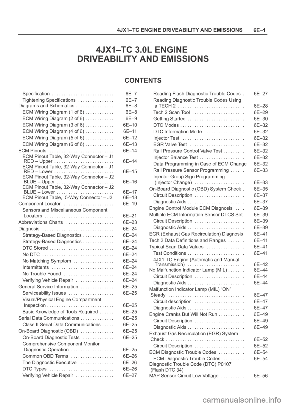
CONTENTS
Specification 6E–7. . . . . . . . . . . . . . . . . . . . . . . . . .
Tightening Specifications 6E–7. . . . . . . . . . . . . . .
Diagrams and Schematics 6E–8. . . . . . . . . . . . . . . .
ECM Wiring Diagram (1 of 6) 6E–8. . . . . . . . . . . .
ECM Wiring Diagram (2 of 6) 6E–9. . . . . . . . . . . .
ECM Wiring Diagram (3 of 6) 6E–10. . . . . . . . . . . .
ECM Wiring Diagram (4 of 6) 6E–11. . . . . . . . . . . .
ECM Wiring Diagram (5 of 6) 6E–12. . . . . . . . . . . .
ECM Wiring Diagram (6 of 6) 6E–13. . . . . . . . . . . .
ECM Pinouts 6E–14. . . . . . . . . . . . . . . . . . . . . . . . . . .
ECM Pinout Table, 32-Way Connector – J1
RED – Upper 6E–14. . . . . . . . . . . . . . . . . . . . . . . . .
ECM Pinout Table, 32-Way Connector – J1
RED – Lower 6E–15. . . . . . . . . . . . . . . . . . . . . . . . .
ECM Pinout Table, 32-Way Connector – J2
BLUE – Upper 6E–16. . . . . . . . . . . . . . . . . . . . . . . .
ECM Pinout Table, 32-Way Connector – J2
BLUE – Lower 6E–17. . . . . . . . . . . . . . . . . . . . . . . .
ECM Pinout Table, 5-Way Connector – J3 6E–18
Component Locator 6E–19. . . . . . . . . . . . . . . . . . . . .
Sensors and Miscellaneous Component
Locators 6E–21. . . . . . . . . . . . . . . . . . . . . . . . . . . . .
Abbreviations Charts 6E–23. . . . . . . . . . . . . . . . . . . .
Diagnosis 6E–24. . . . . . . . . . . . . . . . . . . . . . . . . . . . . .
Strategy-Based Diagnostics 6E–24. . . . . . . . . . . . .
Strategy-Based Diagnostics 6E–24. . . . . . . . . . . . .
DTC Stored 6E–24. . . . . . . . . . . . . . . . . . . . . . . . . . .
No DTC 6E–24. . . . . . . . . . . . . . . . . . . . . . . . . . . . . .
No Matching Symptom 6E–24. . . . . . . . . . . . . . . . .
Intermittents 6E–24. . . . . . . . . . . . . . . . . . . . . . . . . .
No Trouble Found 6E–24. . . . . . . . . . . . . . . . . . . . .
Verifying Vehicle Repair 6E–24. . . . . . . . . . . . . . . .
General Service Information 6E–25. . . . . . . . . . . . . .
Serviceability Issues 6E–25. . . . . . . . . . . . . . . . . . .
Visual/Physical Engine Compartment
Inspection 6E–25. . . . . . . . . . . . . . . . . . . . . . . . . . . .
Basic Knowledge of Tools Required 6E–25. . . . . .
Serial Data Communications 6E–25. . . . . . . . . . . . . .
Class II Serial Data Communications 6E–25. . . . .
On-Board Diagnostic (OBD) 6E–25. . . . . . . . . . . . . .
On-Board Diagnostic Tests 6E–25. . . . . . . . . . . . .
Comprehensive Component Monitor
Diagnostic Operation 6E–25. . . . . . . . . . . . . . . . . .
Common OBD Terms 6E–26. . . . . . . . . . . . . . . . . .
The Diagnostic Executive 6E–26. . . . . . . . . . . . . . .
DTC Types 6E–26. . . . . . . . . . . . . . . . . . . . . . . . . . .
Verifying Vehicle Repair 6E–27. . . . . . . . . . . . . . . . Reading Flash Diagnostic Trouble Codes 6E–27.
Reading Diagnostic Trouble Codes Using
a TECH 2 6E–28. . . . . . . . . . . . . . . . . . . . . . . . . . . .
Tech 2 Scan Tool 6E–29. . . . . . . . . . . . . . . . . . . . . .
Getting Started 6E–30. . . . . . . . . . . . . . . . . . . . . . . .
DTC Modes 6E–32. . . . . . . . . . . . . . . . . . . . . . . . . . .
DTC Information Mode 6E–32. . . . . . . . . . . . . . . . .
Injector Test 6E–32. . . . . . . . . . . . . . . . . . . . . . . . . .
EGR Valve Test 6E–32. . . . . . . . . . . . . . . . . . . . . . .
Rail Pressure Control Valve Test 6E–32. . . . . . . . .
Injector Balance Test 6E–32. . . . . . . . . . . . . . . . . . .
Data Programming in Case of ECM Change 6E–32
Rail Pressure Sensor Programming 6E–33. . . . . .
Injector Group Sign Programming
(Injector Change) 6E–33. . . . . . . . . . . . . . . . . . . . .
On-Board Diagnostic (OBD) System Check 6E–35.
Circuit Description 6E–37. . . . . . . . . . . . . . . . . . . . .
Diagnostic Aids 6E–37. . . . . . . . . . . . . . . . . . . . . . . .
Engine Control Module ECM Diagnosis 6E–39. . . .
Multiple ECM Information Sensor DTCS Set 6E–39
Circuit Description 6E–39. . . . . . . . . . . . . . . . . . . . .
Diagnostic Aids 6E–39. . . . . . . . . . . . . . . . . . . . . . . .
EGR (Exhaust Gas Recirculation) Diagnosis 6E–41
Tech 2 Data Definitions and Ranges 6E–41. . . . . . .
Typical Scan Data Values 6E–41. . . . . . . . . . . . . . . .
Test Conditions 6E–41. . . . . . . . . . . . . . . . . . . . . . . .
4JX1-TC Engine (Automatic and Manual
Transmission) 6E–42. . . . . . . . . . . . . . . . . . . . . . . .
No Malfunction Indicator Lamp (MIL) 6E–44. . . . . . .
Circuit Description 6E–44. . . . . . . . . . . . . . . . . . . . .
Diagnostic Aids 6E–44. . . . . . . . . . . . . . . . . . . . . . . .
Malfunction Indicator Lamp (MIL) “ON”
Steady 6E–47. . . . . . . . . . . . . . . . . . . . . . . . . . . . . . . .
Circuit description 6E–47. . . . . . . . . . . . . . . . . . . . .
Diagnostic Aids 6E–47. . . . . . . . . . . . . . . . . . . . . . . .
Engine Cranks But Will Not Run 6E–49. . . . . . . . . . .
Circuit Description 6E–49. . . . . . . . . . . . . . . . . . . . .
Diagnostic Aids 6E–49. . . . . . . . . . . . . . . . . . . . . . . .
Exhaust Gas Recirculation (EGR) System
Check 6E–52. . . . . . . . . . . . . . . . . . . . . . . . . . . . . . . . .
Circuit Description 6E–52. . . . . . . . . . . . . . . . . . . . .
ECM Diagnostic Trouble Codes 6E–54. . . . . . . . . . .
ECM Diagnostic Trouble Codes 6E–54. . . . . . . . .
Diagnostic Trouble Code (DTC) P0107
(Flash DTC 34)
MAP Sensor Circuit Low Voltage 6E–56. . . . . . . . . .
Page 5435 of 6000
6E–6
4JX1–TC ENGINE DRIVEABILITY AND EMISSIONS
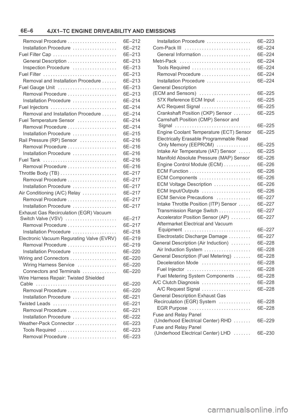
Removal Procedure 6E–212. . . . . . . . . . . . . . . . . . . .
Installation Procedure 6E–212. . . . . . . . . . . . . . . . . .
Fuel Filter Cap 6E–213. . . . . . . . . . . . . . . . . . . . . . . . . .
General Description 6E–213. . . . . . . . . . . . . . . . . . . .
Inspection Procedure 6E–213. . . . . . . . . . . . . . . . . .
Fuel Filter 6E–213. . . . . . . . . . . . . . . . . . . . . . . . . . . . . .
Removal and Installation Procedure 6E–213. . . . . .
Fuel Gauge Unit 6E–213. . . . . . . . . . . . . . . . . . . . . . . .
Removal Procedure 6E–213. . . . . . . . . . . . . . . . . . . .
Installation Procedure 6E–214. . . . . . . . . . . . . . . . . .
Fuel Injectors 6E–214. . . . . . . . . . . . . . . . . . . . . . . . . . .
Removal and Installation Procedure 6E–214. . . . . .
Fuel Temperature Sensor 6E–214. . . . . . . . . . . . . . . .
Removal Procedure 6E–214. . . . . . . . . . . . . . . . . . . .
Installation Procedure 6E–215. . . . . . . . . . . . . . . . . .
Rail Pressure (RP) Sensor 6E–216. . . . . . . . . . . . . . .
Removal Procedure 6E–216. . . . . . . . . . . . . . . . . . . .
Installation Procedure 6E–216. . . . . . . . . . . . . . . . . .
Fuel Tank 6E–216. . . . . . . . . . . . . . . . . . . . . . . . . . . . . .
Removal Procedure 6E–216. . . . . . . . . . . . . . . . . . . .
Throttle Body (TB) 6E–217. . . . . . . . . . . . . . . . . . . . . . .
Removal Procedure 6E–217. . . . . . . . . . . . . . . . . . . .
Installation Procedure 6E–217. . . . . . . . . . . . . . . . . .
Air Conditioning (A/C) Relay 6E–217. . . . . . . . . . . . . .
Removal Procedure 6E–217. . . . . . . . . . . . . . . . . . . .
Installation Procedure 6E–217. . . . . . . . . . . . . . . . . .
Exhaust Gas Recirculation (EGR) Vacuum
Switch Valve (VSV) 6E–217. . . . . . . . . . . . . . . . . . . . .
Removal Procedure 6E–217. . . . . . . . . . . . . . . . . . . .
Installation Procedure 6E–218. . . . . . . . . . . . . . . . . .
Electronic Vacuum Regurating Valve (EVRV) 6E–219
Removal Procedure 6E–219. . . . . . . . . . . . . . . . . . . .
Installation Procedure 6E–220. . . . . . . . . . . . . . . . . .
Wiring and Connectors 6E–220. . . . . . . . . . . . . . . . . . .
Wiring Harness Service 6E–220. . . . . . . . . . . . . . . .
Connectors and Terminals 6E–220. . . . . . . . . . . . . .
Wire Harness Repair: Twisted Shielded
Cable 6E–220. . . . . . . . . . . . . . . . . . . . . . . . . . . . . . . . .
Removal Procedure 6E–220. . . . . . . . . . . . . . . . . . . .
Installation Procedure 6E–221. . . . . . . . . . . . . . . . . .
Twisted Leads 6E–221. . . . . . . . . . . . . . . . . . . . . . . . . .
Removal Procedure 6E–221. . . . . . . . . . . . . . . . . . . .
Installation Procedure 6E–222. . . . . . . . . . . . . . . . . .
Weather-Pack Connector 6E–223. . . . . . . . . . . . . . . . .
Tools Required 6E–223. . . . . . . . . . . . . . . . . . . . . . . .
Removal Procedure 6E–223. . . . . . . . . . . . . . . . . . . . Installation Procedure 6E–223. . . . . . . . . . . . . . . . . .
Com-Pack III 6E–224. . . . . . . . . . . . . . . . . . . . . . . . . . .
General Information 6E–224. . . . . . . . . . . . . . . . . . . .
Metri-Pack 6E–224. . . . . . . . . . . . . . . . . . . . . . . . . . . . .
Tools Required 6E–224. . . . . . . . . . . . . . . . . . . . . . . .
Removal Procedure 6E–224
. . . . . . . . . . . . . . . . . . . .
Installation Procedure 6E–224. . . . . . . . . . . . . . . . . .
General Description
(ECM and Sensors) 6E–225. . . . . . . . . . . . . . . . . . . . .
57X Reference ECM Input 6E–225. . . . . . . . . . . . . .
A/C Request Signal 6E–225. . . . . . . . . . . . . . . . . . . .
Crankshaft Position (CKP) Sensor 6E–225. . . . . . .
Camshaft Position (CMP) Sensor and
Signal 6E–225. . . . . . . . . . . . . . . . . . . . . . . . . . . . . . .
Engine Coolant Temperature (ECT) Sensor 6E–225
Electrically Erasable Programmable Read
Only Memory (EEPROM) 6E–225. . . . . . . . . . . . . .
Intake Air Temperature (IAT) Sensor 6E–225. . . . .
Manifold Absolute Pressure (MAP) Sensor 6E–226
Engine Control Module (ECM) 6E–226. . . . . . . . . . .
ECM Function 6E–226. . . . . . . . . . . . . . . . . . . . . . . . .
ECM Components 6E–226. . . . . . . . . . . . . . . . . . . . .
ECM Voltage Description 6E–226. . . . . . . . . . . . . . .
ECM Input/Outputs 6E–226. . . . . . . . . . . . . . . . . . . .
ECM Service Precautions 6E–227. . . . . . . . . . . . . .
Intake Throttle Position (ITP) Sensor 6E–227. . . . .
Transmission Range Switch 6E–227. . . . . . . . . . . . .
Accelerator Position Sensor (AP) 6E–227. . . . . . . .
Aftermarket Electrical and Vacuum
Equipment 6E–227. . . . . . . . . . . . . . . . . . . . . . . . . . .
Electrostatic Discharge Damage 6E–227. . . . . . . . .
General Description (Air Induction) 6E–228. . . . . . . .
Air Induction System 6E–228. . . . . . . . . . . . . . . . . . .
General Description (Fuel Metering) 6E–228. . . . . . .
Deceleration Mode 6E–228. . . . . . . . . . . . . . . . . . . .
Fuel Injector 6E–228. . . . . . . . . . . . . . . . . . . . . . . . . .
Fuel Metering System Components 6E–228. . . . . .
A/C Clutch Diagnosis 6E–228. . . . . . . . . . . . . . . . . . . .
A/C Request Signal 6E–228. . . . . . . . . . . . . . . . . . . .
General Description Exhaust Gas
Recirculation (EGR) System 6E–228. . . . . . . . . . . . .
EGR Purpose 6E–228. . . . . . . . . . . . . . . . . . . . . . . . .
Fuse and Relay Panel
(Underhood Electrical Center) RHD 6E–229. . . . . . .
Fuse and Relay Panel
(Underhood Electrical Center) LHD 6E–230. . . . . . .
Page 5437 of 6000

6E–8
4JX1–TC ENGINE DRIVEABILITY AND EMISSIONS
Diagrams and Schematics
ECM Wiring Diagram (1 of 6)
060RW127