wiring OPEL FRONTERA 1998 Workshop Manual
[x] Cancel search | Manufacturer: OPEL, Model Year: 1998, Model line: FRONTERA, Model: OPEL FRONTERA 1998Pages: 6000, PDF Size: 97 MB
Page 4923 of 6000

6E–266
ENGINE DRIVEABILITY AND EMISSIONS
Surges and/or Chuggles Symptom
StepNo Ye s Va l u e ( s ) Action
101. Check for proper ignition voltage output with spark
tester J 26792 (ST-125). Refer to
Electric Ignition
System
for procedure.
2. If a problem is found, repair as necessary.
Was a problem found?
—Verify repairGo to Step 11
111. Check for a loose ignition coil ground.
Refer to
Electric Ignition System.
2. If a problem is found, repair as necessary.
Was a problem found?
—Verify repairGo to Step 12
121. Check the ignition coils for cracks or carbon
tracking.
2. If a problem is found, repair as necessary.
Was a problem found?
—Verify repairGo to Step 13
131. Remove the spark plugs and check for wet plugs,
cracks, wear, improper gap, burned electrodes, or
heavy deposits. Refer to
Electronic Ignition
System
.
NOTE: If spark plugs are gas or oil fouled, the cause of
the fouling must be determined before replacing the
spark plugs.
2. If a problem is found, repair as necessary.
Was a problem found?
—Verify repairGo to Step 14
141. Check the injector connections.
2. If any of the injector connectors are connected to an
incorrect cylinder, correct as necessary.
Was a problem found?
—Verify repairGo to Step 15
151. Check PCM grounds for the cleanliness, tightness
and proper locations. Refer to the PCM wiring
diagrams in
Electrical Diagnosis.
2. If a problem is found, repair as necessary.
Was a problem found?
—Verify repairGo to Step 16
161. Check MAF sensor connections.
2. If a problem is found, replace the faulty terminals as
necessary. Refer to
Electrical Diagnosis for wiring
repair procedures.
Was a problem found?
—Verify repairGo to Step 17
171. Visually/physically check vacuum hoses for splits,
kinks, and proper connections and routing as
shown on the “Vehicle Emission Control
Information” label.
2. If a problem is found, repair as necessary.
Was a problem found?
—Verify repairGo to Step 18
Page 4926 of 6000

6E–269 ENGINE DRIVEABILITY AND EMISSIONS
Lack of Power, Sluggish or Spongy Symptom
StepNo Ye s Va l u e ( s ) Action
111. Check the PCM grounds for the cleanliness,
tightness and proper locations. Refer to the PCM
wiring diagrams in
Electrical Diagnosis.
2. If a problem is found, repair as necessary.
Was a problem found?
—Verify repairGo to Step 12
121. Check the exhaust system for possible restriction:
Inspect the exhaust system for damaged or
collapsed pipes.
Inspect the muffler for heat distress or possible
internal failure.
Check for a possible plugged three-way
catalytic converter by checking the exhaust
system back pressure. Refer to
Restricted
Exhaust System Check
.
2. If a problem is found, repair as necessary.
Was a problem found?
—Verify repairGo to Step 13
131. Check the torque converter clutch (TCC) for proper
operation. Refer to
4L30-E Transmission
Diagnosis
.
2. If a problem is found, repair as necessary.
Was a problem found?
—Verify repairGo to Step 14
141. Check for an engine mechanical problem. Check
for low compression, incorrect or worn camshaft,
loose timing belt, etc. Refer to
Engine Mechanical.
2. If a problem is found, repair as necessary.
Was a problem found?
—Verify repairGo to Step 15
151. Review all diagnostic procedures within this table.
2. If all procedures have been completed and no
malfunctions have been found, review/inspect the
following:
Visual/physical inspection
Te c h 2 d a t a
Freeze Frame data/Failure Records buffer
All electrical connections within a suspected
circuit and/or system.
3. If a problem is found, repair as necessary.
Was a problem found?
—Verify repair
Contact
Te c h n i c a l
Assistance
Page 4929 of 6000

6E–272
ENGINE DRIVEABILITY AND EMISSIONS
Rough, Unstable, or Incorrect Idle, Stalling Symptom
StepActionVa l u e ( s )Ye sNo
1DEFINITION:
Engine runs unevenly at idle. If severe, the engine or
vehicle may shake. Engine idle speed may vary in
RPM. Either condition may be severe enough to stall
the engine.
Was the “On-Board Diagnostic (OBD) System Check”
performed?
—Go to Step 2
Go to OBD
System
Check
21. Perform a bulletin search.
2. If a bulletin that addresses the symptom is found,
correct the condition as instructed in the bulletin.
Was a bulletin found that addresses the symptom?
—Go to Step 13Go to Step 3
3Was a visual/physical check performed?
—Go to Step 4
Go to
Visual/Physic
al Check
41. Check the PCM grounds for cleanliness, tightness
and proper routing. Refer to the PCM wiring
diagrams in
Electrical Diagnosis.
2. If a problem is found, repair as necessary.
Was a problem found?
—Verify repairGo to Step 5
5Observe the long term fuel trim on Tech 2.
Is the long term fuel trim significantly in the negative
range (rich condition)?
—Go to Step 6Go to Step 7
61. Check items that can cause the engine to run rich.
Refer to
Diagnostic Aids in DTC P0172 Diagnostic
Support
.
2. If a problem is found, repair as necessary.
Was a problem found?
—Verify repairGo to Step 9
7Is the long term fuel trim significantly in the positive
range (lean condition)?
—Go to Step 8Go to Step 9
81. Check items that can cause the engine to run lean.
Refer to
Diagnostic Aids in DTC P0171 Diagnostic
Support
.
2. If a problem is found, repair as necessary.
Was a problem found?
—Verify repairGo to Step 9
91. Check for incorrect idle speed. Ensure that the
following conditions are present:
The engine is fully warm.
The accessories are “OFF.”
2. Using Tech 2, monitor the IAC position.
Is the IAC position within the specified values?Between 10
and 50
counts
Go to Step 11Go to Step 10
Page 4939 of 6000

6E–282
ENGINE DRIVEABILITY AND EMISSIONS
Cuts Out, Misses Symptom
StepActionVa l u e ( s )Ye sNo
1DEFINITION:
Steady pulsation or jerking that follows engine speed;
usually more pronounced as engine load increases.
Was the “On-Board Diagnostic (OBD) System Check”
performed?
—Go to Step 2
Go to OBD
System
Check
21. Perform a bulletin search.
2. If a bulletin that addresses the symptom is found,
correct the condition as instructed in the bulletin.
Was a bulletin found that addresses the symptom?
—Go to Step 13Go to Step 3
3Was a visual/physical check performed?
—Go to Step 4
Go to
Visual/Physic
al Check
41. Check the PCM grounds for clearness, tightness
and proper routing. Refer to the PCM wiring
diagrams in
Electrical Diagnosis.
2. If a problem is found, repair as necessary.
Was a problem found?
—Verify repairGo to Step 5
5Observe the long term fuel trim on Tech 2.
Is the long term fuel trim significantly in the negative
range (rich condition)?
—Go to Step 6Go to Step 7
61. Check items that can cause the engine to run rich.
Refer to
Diagnostic Aids in DTC P0172 Diagnostic
Support
.
2. If a problem is found, repair as necessary.
Was a problem found?
—Verify repairGo to Step 9
7Is the long term fuel trim significantly in the positive
range (lean condition)?
—Go to Step 8Go to Step 9
81. Check items that can cause the engine to run lean.
Refer to
Diagnostic Aids in DTC P0171 Diagnostic
Support
.
2. If a problem is found, repair as necessary.
Was a problem found?
—Verify repairGo to Step 9
91. Check for incorrect idle speed. Ensure that the
following conditions are present:
The engine is fully warm.
The accessories are “off.”
2. Using Tech 2, monitor the IAC position.
Is the IAC position within the specified values?Between 5
and 50
counts
Go to Step 11Go to Step 10
Page 4943 of 6000
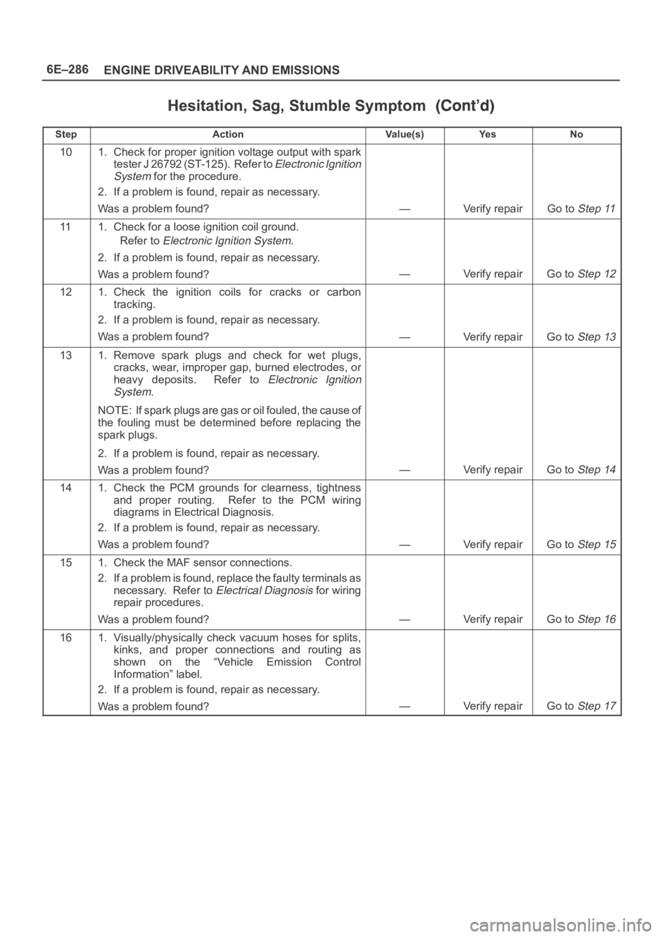
6E–286
ENGINE DRIVEABILITY AND EMISSIONS
Hesitation, Sag, Stumble Symptom
StepNo Ye s Va l u e ( s ) Action
101. Check for proper ignition voltage output with spark
tester J 26792 (ST-125). Refer to
Electronic Ignition
System
for the procedure.
2. If a problem is found, repair as necessary.
Was a problem found?
—Verify repairGo to Step 11
111. Check for a loose ignition coil ground.
Refer to
Electronic Ignition System.
2. If a problem is found, repair as necessary.
Was a problem found?
—Verify repairGo to Step 12
121. Check the ignition coils for cracks or carbon
tracking.
2. If a problem is found, repair as necessary.
Was a problem found?
—Verify repairGo to Step 13
131. Remove spark plugs and check for wet plugs,
cracks, wear, improper gap, burned electrodes, or
heavy deposits. Refer to
Electronic Ignition
System
.
NOTE: If spark plugs are gas or oil fouled, the cause of
the fouling must be determined before replacing the
spark plugs.
2. If a problem is found, repair as necessary.
Was a problem found?
—Verify repairGo to Step 14
141. Check the PCM grounds for clearness, tightness
and proper routing. Refer to the PCM wiring
diagrams in Electrical Diagnosis.
2. If a problem is found, repair as necessary.
Was a problem found?
—Verify repairGo to Step 15
151. Check the MAF sensor connections.
2. If a problem is found, replace the faulty terminals as
necessary. Refer to
Electrical Diagnosis for wiring
repair procedures.
Was a problem found?
—Verify repairGo to Step 16
161. Visually/physically check vacuum hoses for splits,
kinks, and proper connections and routing as
shown on the “Vehicle Emission Control
Information” label.
2. If a problem is found, repair as necessary.
Was a problem found?
—Verify repairGo to Step 17
Page 4951 of 6000
6E–294
ENGINE DRIVEABILITY AND EMISSIONS
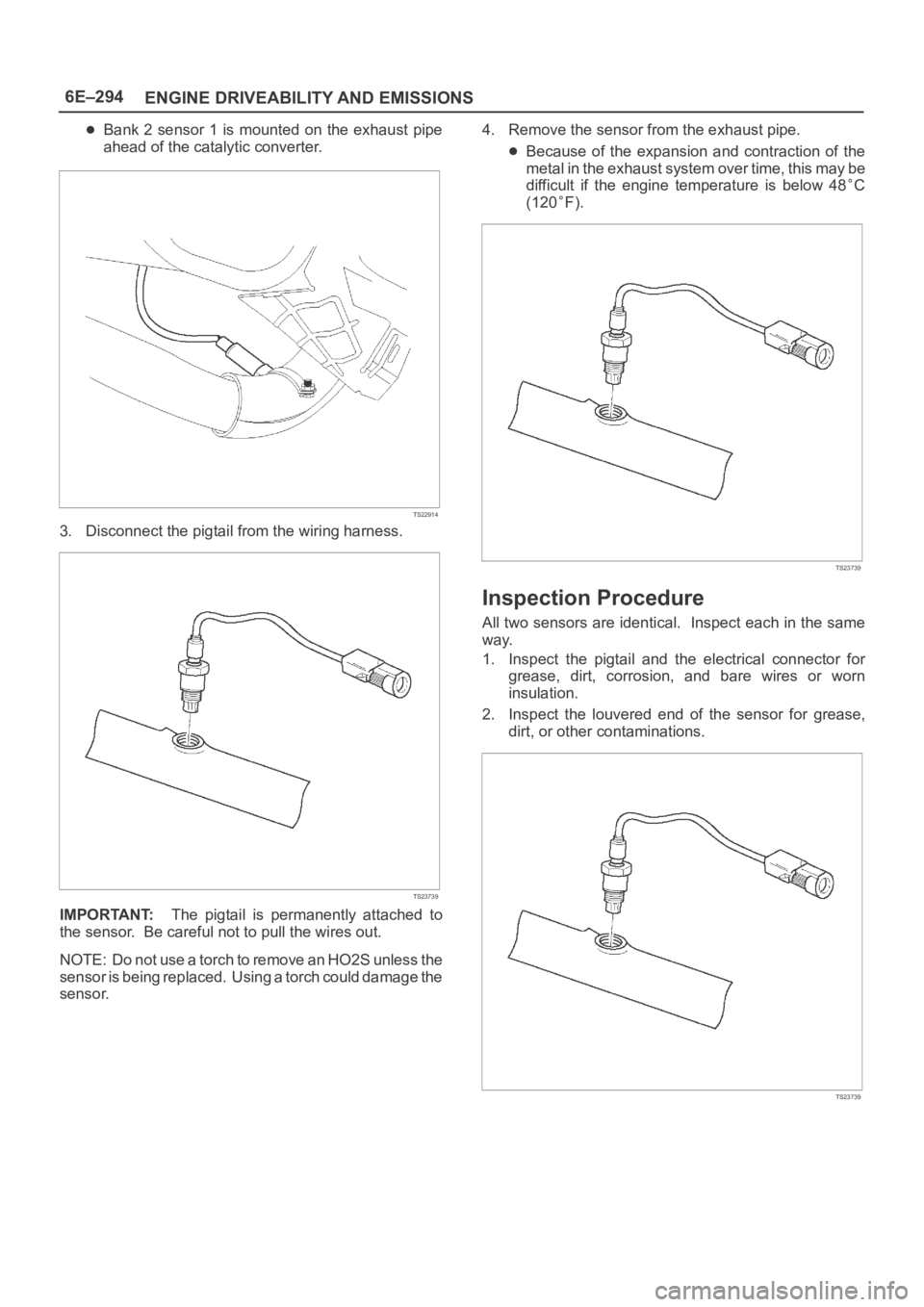
Bank 2 sensor 1 is mounted on the exhaust pipe
ahead of the catalytic converter.
TS22914
3. Disconnect the pigtail from the wiring harness.
TS23739
IMPORTANT:The pigtail is permanently attached to
the sensor. Be careful not to pull the wires out.
NOTE: Do not use a torch to remove an HO2S unless the
sensor is being replaced. Using a torch could damage the
sensor.4. Remove the sensor from the exhaust pipe.
Because of the expansion and contraction of the
metal in the exhaust system over time, this may be
difficult if the engine temperature is below 48
C
(120
F).
TS23739
Inspection Procedure
All two sensors are identical. Inspect each in the same
way.
1. Inspect the pigtail and the electrical connector for
grease, dirt, corrosion, and bare wires or worn
insulation.
2. Inspect the louvered end of the sensor for grease,
dirt, or other contaminations.
TS23739
Page 4952 of 6000
6E–295 ENGINE DRIVEABILITY AND EMISSIONS
Installation Procedure
IMPORTANT:
A special anti-seize compound, P/N 5613695, is used
on the HO2S threads. This compound consists of
glass beads suspended in a liquid graphite solution.
The graphite burns away with engine heat, but the
glass beads will remain, making the sensor easier to
remove.
New or service sensors will already have the
compound applied to the threads. If a sensor is
removed and is to be reinstalled for any reason, the
threads must have anti-seize compound applied.
1. Apply anti-seize compound or the equivalent to the
threads of the oxygen sensor, if necessary.
2. Install the oxygen sensor on the exhaust pipe in its
original position.
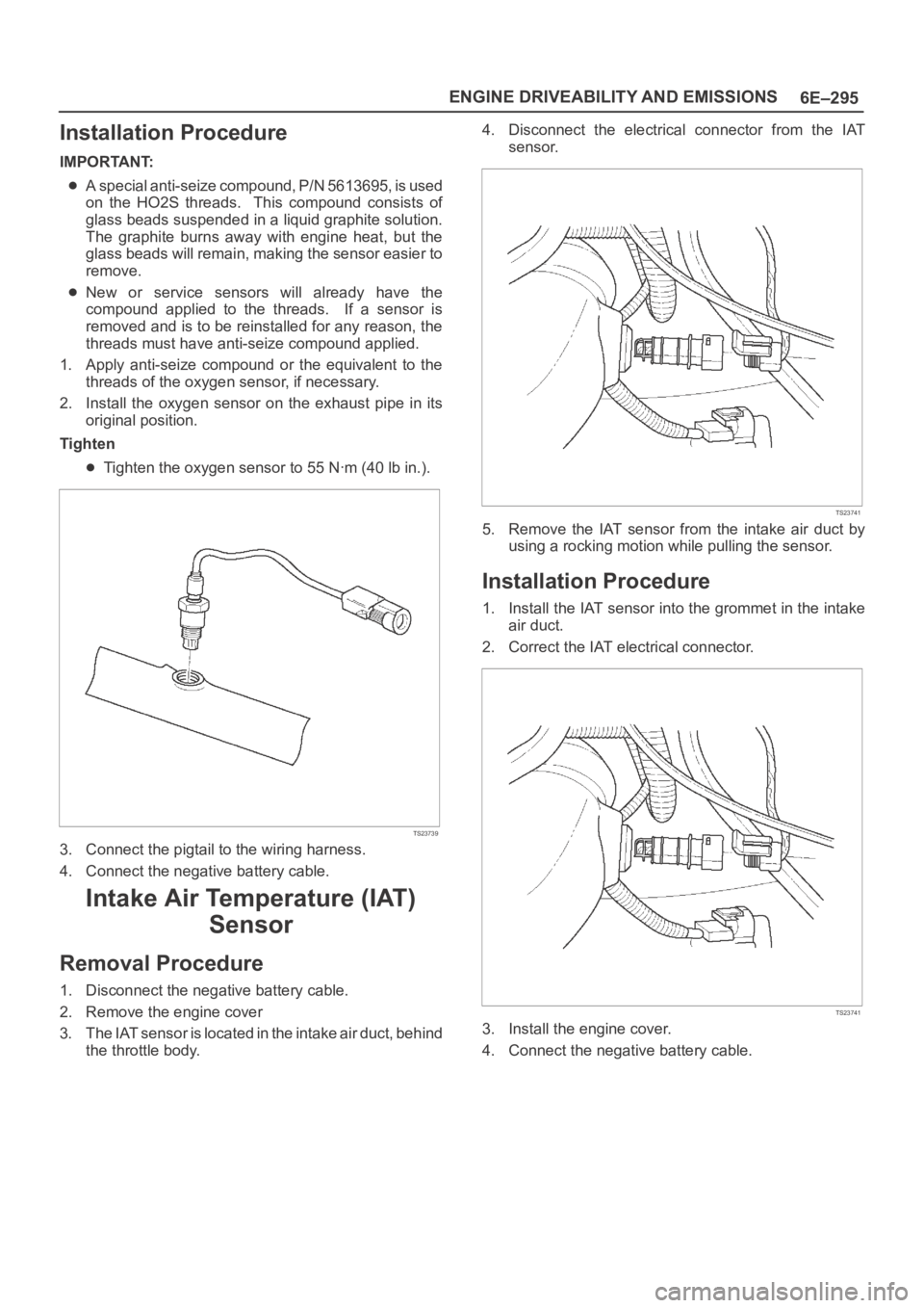
Tighten
Tighten the oxygen sensor to 55 Nꞏm (40 lb in.).
TS23739
3. Connect the pigtail to the wiring harness.
4. Connect the negative battery cable.
Intake Air Temperature (IAT)
Sensor
Removal Procedure
1. Disconnect the negative battery cable.
2. Remove the engine cover
3. The IAT sensor is located in the intake air duct, behind
the throttle body.4. Disconnect the electrical connector from the IAT
sensor.
TS23741
5. Remove the IAT sensor from the intake air duct by
using a rocking motion while pulling the sensor.
Installation Procedure
1. Install the IAT sensor into the grommet in the intake
air duct.
2. Correct the IAT electrical connector.
TS23741
3. Install the engine cover.
4. Connect the negative battery cable.
Page 4957 of 6000
6E–300
ENGINE DRIVEABILITY AND EMISSIONS
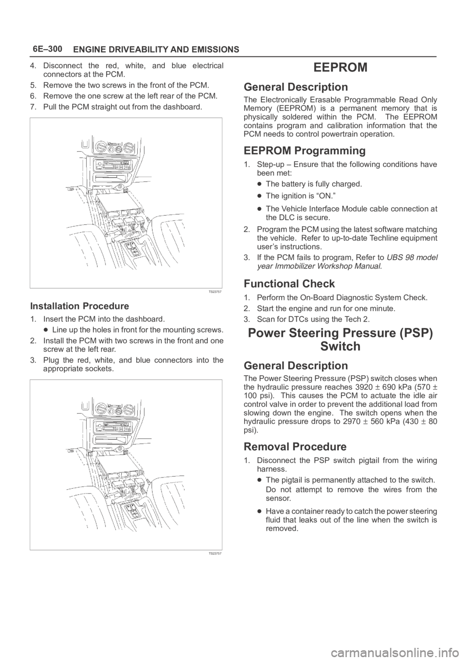
4. Disconnect the red, white, and blue electrical
connectors at the PCM.
5. Remove the two screws in the front of the PCM.
6. Remove the one screw at the left rear of the PCM.
7. Pull the PCM straight out from the dashboard.
TS23757
Installation Procedure
1. Insert the PCM into the dashboard.
Line up the holes in front for the mounting screws.
2. Install the PCM with two screws in the front and one
screw at the left rear.
3. Plug the red, white, and blue connectors into the
appropriate sockets.
TS23757
EEPROM
General Description
The Electronically Erasable Programmable Read Only
Memory (EEPROM) is a permanent memory that is
physically soldered within the PCM. The EEPROM
contains program and calibration information that the
PCM needs to control powertrain operation.
EEPROM Programming
1. Step-up – Ensure that the following conditions have
been met:
The battery is fully charged.
The ignition is “ON.”
The Vehicle Interface Module cable connection at
the DLC is secure.
2. Program the PCM using the latest software matching
the vehicle. Refer to up-to-date Techline equipment
user’s instructions.
3. If the PCM fails to program, Refer to
UBS 98 model
year Immobilizer Workshop Manual.
Functional Check
1. Perform the On-Board Diagnostic System Check.
2. Start the engine and run for one minute.
3. Scan for DTCs using the Tech 2.
Power Steering Pressure (PSP)
Switch
General Description
The Power Steering Pressure (PSP) switch closes when
the hydraulic pressure reaches 3920
690 kPa (570
100 psi). This causes the PCM to actuate the idle air
control valve in order to prevent the additional load from
slowing down the engine. The switch opens when the
hydraulic pressure drops to 2970
560 kPa (430 80
psi).
Removal Procedure
1. Disconnect the PSP switch pigtail from the wiring
harness.
The pigtail is permanently attached to the switch.
Do not attempt to remove the wires from the
sensor.
Have a container ready to catch the power steering
fluid that leaks out of the line when the switch is
removed.
Page 4958 of 6000

6E–301 ENGINE DRIVEABILITY AND EMISSIONS
2. Remove the PSP switch from the power steering line.
Plug the line to prevent excessive loss of fluid and
possible contamination of the power steering
system.
TS23760
Installation Procedure
1. Install the PSP switch in the power steering line.
TS23760
2. Connect the PSP switch pigtail to the wiring harness.
3. Check the power steering fluid level. Refer to
Power
Steering
.
4. Start the engine. Watch the PSP switch for signs of
fluid leakage.
Throttle Position (TP) Sensor
Removal Procedure
1. Disconnect the negative battery cable.
2. Disconnect the TPS electrical connector.3. Remove the bolts and the TP sensor from the throttle
body.
TS23747
NOTE: Do not clean the TP sensor by soaking it in
solvent. The sensor will be damaged as a result.
Function Check
Use a Tech 2 to check the TP sensor output voltage at
closed throttle.
The voltage should be under 0.85 volt.
If the reading is greater than 0.85 volt, check the
throttle shaft to see if it is binding. Check that the
throttle cable is properly adjusted, also. Refer to
Throttle Cable Adjustment.
If the throttle shaft is not binding and the throttle cable
is properly adjusted, install a new TP sensor.
Installation Procedure
1. Install the TP sensor on the throttle body with the
bolts.
TS23747
Page 4965 of 6000
6E–308
ENGINE DRIVEABILITY AND EMISSIONS
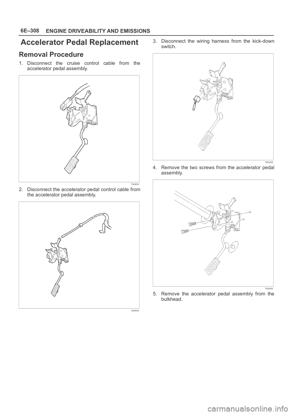
Accelerator Pedal Replacement
Removal Procedure
1. Disconnect the cruise control cable from the
accelerator pedal assembly.
TS24053
2. Disconnect the accelerator pedal control cable from
the accelerator pedal assembly.
TS24054
3. Disconnect the wiring harness from the kick-down
switch.
TS24038
4. Remove the two screws from the accelerator pedal
assembly.
TS24055
5. Remove the accelerator pedal assembly from the
bulkhead.