engine OPEL FRONTERA 1998 Workshop Manual
[x] Cancel search | Manufacturer: OPEL, Model Year: 1998, Model line: FRONTERA, Model: OPEL FRONTERA 1998Pages: 6000, PDF Size: 97 MB
Page 1492 of 6000
6G–13 ENGINE LUBRICATION
Oil Filter
Removal
1. Disconnect battery ground cable.
2. Drain engine oil.
3. Remove oil filter using 5-8840-0203-0 filter wrench.
Installation
1. Clean filter fitting surface and apply small amount of
engine oil to sealing surface.
2. Install oil filter cartridge by hand until it comes in
contact with sealing surface then rotate additional 2/3
turn to tighten using 5-8840-0203-0 filter wrench.
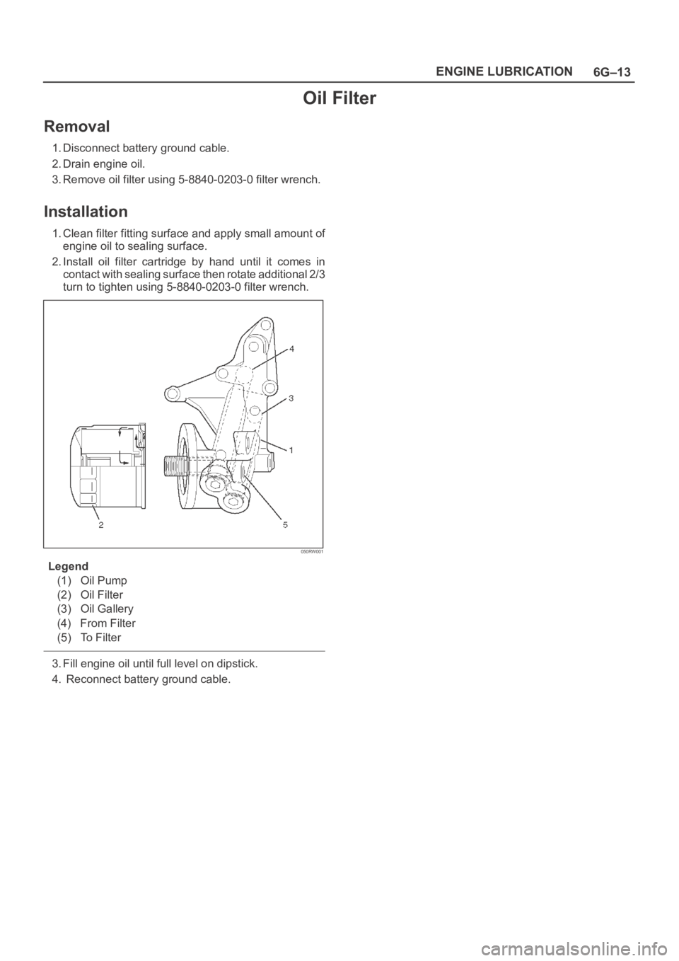
050RW001
Legend
(1) Oil Pump
(2) Oil Filter
(3) Oil Gallery
(4) From Filter
(5) To Filter
3. Fill engine oil until full level on dipstick.
4. Reconnect battery ground cable.
Page 1493 of 6000
6G–14
ENGINE LUBRICATION
Main Data and Specification
General Specification
ItemSpecificationsItem6VD16VE1
Oil capacity5.3 liters
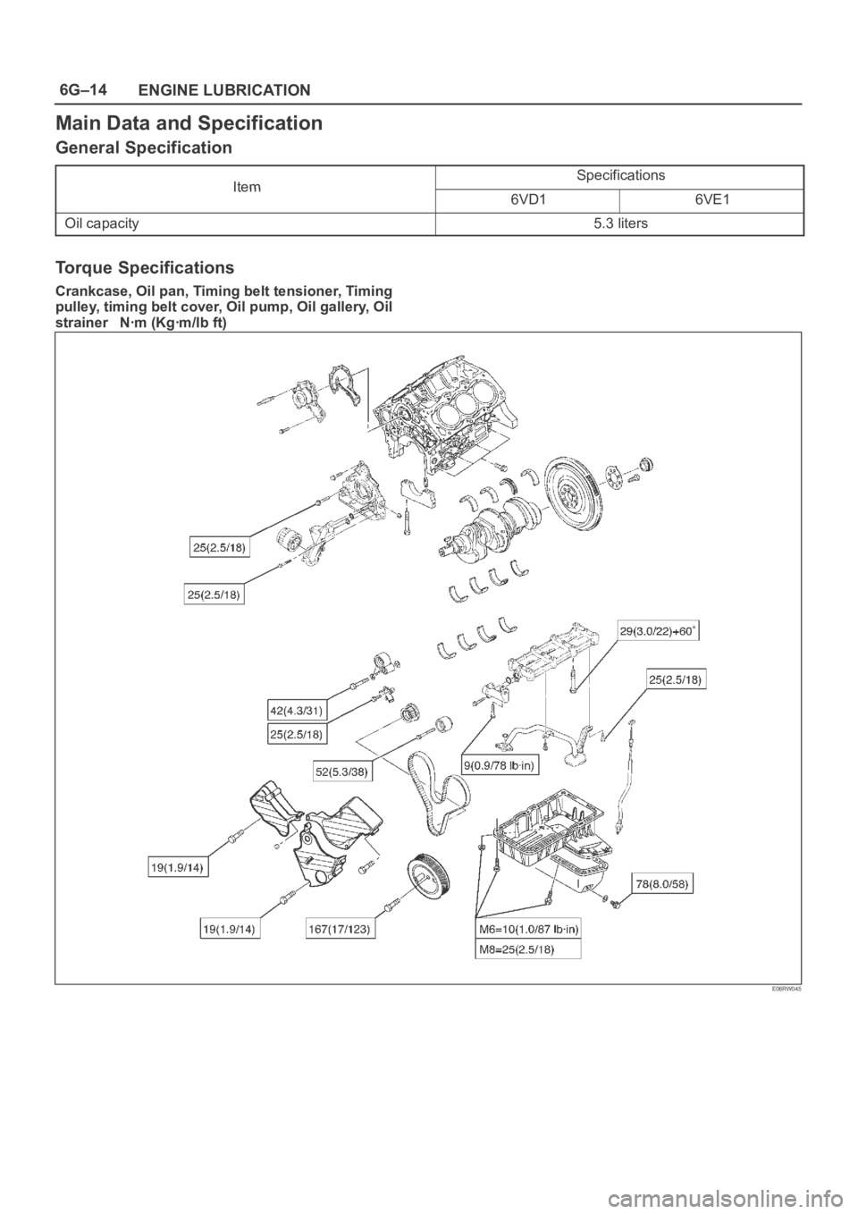
Torque Specifications
Crankcase, Oil pan, Timing belt tensioner, Timing
pulley, timing belt cover, Oil pump, Oil gallery, Oil
strainer Nꞏm (Kgꞏm/lb ft)
E06RW045
Page 1494 of 6000
6G–15 ENGINE LUBRICATION
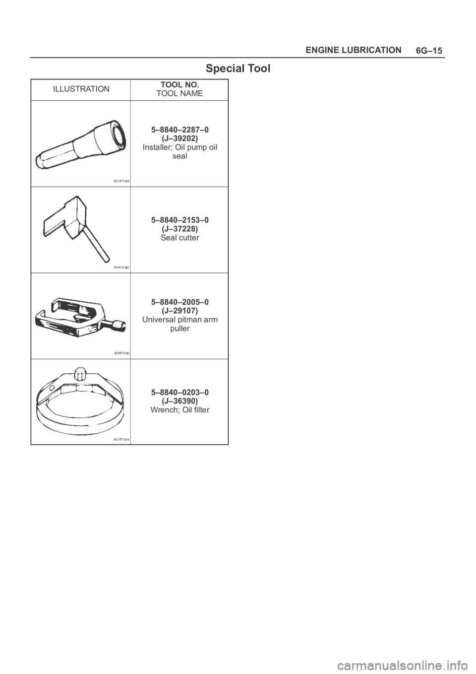
Special Tool
ILLUSTRATIONTOOL NO.
TOOL NAME
5–8840–2287–0
(J–39202)
Installer; Oil pump oil
seal
5–8840–2153–0
(J–37228)
Seal cutter
5–8840–2005–0
(J–29107)
Universal pitman arm
puller
5–8840–0203–0
(J–36390)
Wrench; Oil filter
Page 1495 of 6000
6H–1 ENGINE SPEED CONTROL SYSTEM
ENGINE
ENGINE SPEED CONTROL SYSTEM
CONTENTS
Service Precaution 6H–1. . . . . . . . . . . . . . . . . . . . . .
Accelerator Pedal Control Cable 6H–2. . . . . . . . . .
Removal 6H–2. . . . . . . . . . . . . . . . . . . . . . . . . . . . .
Inspection 6H–2. . . . . . . . . . . . . . . . . . . . . . . . . . . .
Installation 6H–2. . . . . . . . . . . . . . . . . . . . . . . . . . . .
Adjustment 6H–2. . . . . . . . . . . . . . . . . . . . . . . . . . . Accelerator Pedal 6H–3. . . . . . . . . . . . . . . . . . . . . . .
Accelerator Pedal and Associated Parts 6H–3. .
Removal 6H–3. . . . . . . . . . . . . . . . . . . . . . . . . . . . .
Installation 6H–3. . . . . . . . . . . . . . . . . . . . . . . . . . . .
Adjustment 6H–3. . . . . . . . . . . . . . . . . . . . . . . . . . .
Service Precaution
WARNING: IF SO EQUIPPED WITH A
SUPPLEMENTAL RESTRAINT SYSTEM (SRS),
REFER TO THE SRS COMPONENT AND WIRING
LOCATION VIEW IN ORDER TO DETERMINE
WHETHER YOU ARE PERFORMING SERVICE ON OR
NEAR THE SRS COMPONENTS OR THE SRS
WIRING. WHEN YOU ARE PERFORMING SERVICE
ON OR NEAR THE SRS COMPONENTS OR THE SRS
WIRING, REFER TO THE SRS SERVICE
INFORMATION. FAILURE TO FOLLOW WARNINGS
COULD RESULT IN POSSIBLE AIR BAG
DEPLOYMENT, PERSONAL INJURY, OR
OTHERWISE UNNEEDED SRS SYSTEM REPAIRS.
CAUTION: Always use the correct fastener in the
proper location. When you replace a fastener, use
ONLY the exact part number for that application.
ISUZU will call out those fasteners that require a
replacement after removal. ISUZU will also call out
the fasteners that require thread lockers or thread
sealant. UNLESS OTHERWISE SPECIFIED, do not
use supplemental coatings (Paints, greases, or other
corrosion inhibitors) on threaded fasteners or
fastener joint interfaces. Generally, such coatings
adversely affect the fastener torque and the joint
clamping force, and may damage the fastener. When
you install fasteners, use the correct tightening
sequence and specifications. Following these
instructions can help you avoid damage to parts and
systems.
Page 1496 of 6000
6H–2
ENGINE SPEED CONTROL SYSTEM
Accelerator Pedal Control Cable
Removal
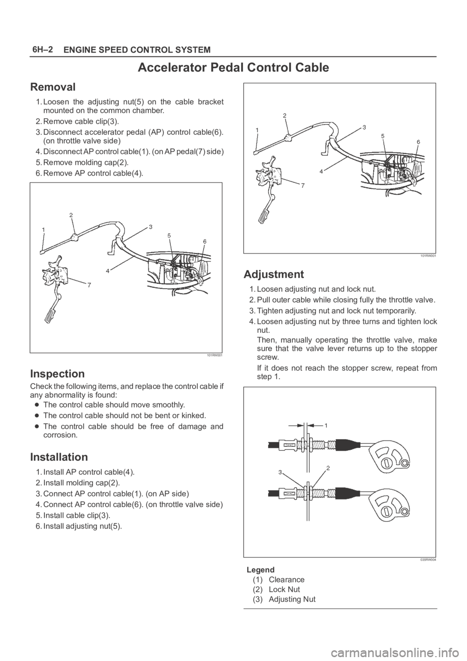
1. Loosen the adjusting nut(5) on the cable bracket
mounted on the common chamber.
2. Remove cable clip(3).
3. Disconnect accelerator pedal (AP) control cable(6).
(on throttle valve side)
4. Disconnect AP control cable(1). (on AP pedal(7) side)
5. Remove molding cap(2).
6. Remove AP control cable(4).
101RW001
Inspection
Check the following items, and replace the control cable if
any abnormality is found:
The control cable should move smoothly.
The control cable should not be bent or kinked.
The control cable should be free of damage and
corrosion.
Installation
1. Install AP control cable(4).
2. Install molding cap(2).
3. Connect AP control cable(1). (on AP side)
4. Connect AP control cable(6). (on throttle valve side)
5. Install cable clip(3).
6. Install adjusting nut(5).
101RW001
Adjustment
1. Loosen adjusting nut and lock nut.
2. Pull outer cable while closing fully the throttle valve.
3. Tighten adjusting nut and lock nut temporarily.
4. Loosen adjusting nut by three turns and tighten lock
nut.
Then, manually operating the throttle valve, make
sure that the valve lever returns up to the stopper
screw.
If it does not reach the stopper screw, repeat from
step 1.
035RW004
Legend
(1) Clearance
(2) Lock Nut
(3) Adjusting Nut
Page 1497 of 6000
6H–3 ENGINE SPEED CONTROL SYSTEM
Accelerator Pedal
Accelerator Pedal and Associated
Parts
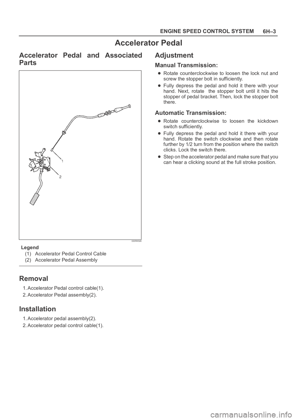
035RW028
Legend
(1) Accelerator Pedal Control Cable
(2) Accelerator Pedal Assembly
Removal
1. Accelerator Pedal control cable(1).
2. Accelerator Pedal assembly(2).
Installation
1. Accelerator pedal assembly(2).
2. Accelerator pedal control cable(1).
Adjustment
Manual Transmission:
Rotate counterclockwise to loosen the lock nut and
screw the stopper bolt in sufficiently.
Fully depress the pedal and hold it there with your
hand. Next, rotate the stopper bolt until it hits the
stopper of pedal bracket. Then, lock the stopper bolt
there.
Automatic Transmission:
Rotate counterclockwise to loosen the kickdown
switch sufficiently.
Fully depress the pedal and hold it there with your
hand. Rotate the switch clockwise and then rotate
further by 1/2 turn from the position where the switch
clicks. Lock the switch there.
Step on the accelerator pedal and make sure that you
can hear a clicking sound at the full stroke position.
Page 1498 of 6000

6H–4
ENGINE SPEED CONTROL SYSTEM
MEMO
Page 1499 of 6000
INDUCTION6J–1
ENGINE
INDUCTION
CONTENTS
Service Precaution 6J–1. . . . . . . . . . . . . . . . . . . . . .
Air Cleaner Element 6J–2. . . . . . . . . . . . . . . . . . . . .
Removal 6J–2. . . . . . . . . . . . . . . . . . . . . . . . . . . . .
Inspection 6J–2. . . . . . . . . . . . . . . . . . . . . . . . . . . .
Installation 6J–2. . . . . . . . . . . . . . . . . . . . . . . . . . . .
Service Precaution
WARNING: IF SO EQUIPPED WITH A
SUPPLEMENTAL RESTRAINT SYSTEM
(SRS),REFER TO THE SRS COMPONENT AND
WIRING LOCATION VIEW IN ORDER TO DETERMINE
WHETHER YOU ARE PERFORMING SERVICE ON OR
NEAR THE SRS COMPONENTS OR THE SRS
WIRING. WHEN YOU ARE PERFORMING SERVICE
ON OR NEAR THE SRS COMPONENTS OR THE SRS
WIRING, REFER TO THE SRS SERVICE
INFORMATION. FAILURE TO FOLLOW WARNINGS
COULD RESULT IN POSSIBLE AIR BAG
DEPLOYMENT, PERSONAL INJURY, OR
OTHERWISE UNNEEDED SRS SYSTEM REPAIRS.
CAUTION: Always use the correct fastener in the
proper location. When you replace a fastener, use
ONLY the exact part number for that application.
ISUZU will call out those fasteners that require a
replacement after removal. ISUZU will also call out
the fasteners that require thread lockers or thread
sealant. UNLESS OTHERWISE SPECIFIED, do not
use supplemental coatings (Paints, greases, or other
corrosion inhibitors) on threaded fasteners or
fastener joint interfaces. Generally, such coatings
adversely affect the fastener torque and the joint
clamping force, and may damage the fastener. When
you install fasteners, use the correct tightening
sequence and specifications. Following these
instructions can help you avoid damage to parts and
systems.
Page 1734 of 6000

ENGINE MECHANICAL 6A – 1
ENGINE
ENGINE MECHANICAL
CONTENTS
General Description . . . . . . . . . . . . . . . . . . . . 6A–2
Service Information . . . . . . . . . . . . . . . . . . . . 6A–3
Service Standard . . . . . . . . . . . . . . . . . . . . . . 6A–6
Servicing . . . . . . . . . . . . . . . . . . . . . . . . . . . . 6A–9
Tightening Torque . . . . . . . . . . . . . . . . . . . . . 6A–14
Special Tools . . . . . . . . . . . . . . . . . . . . . . . . . 6A–25
Engine Assembly . . . . . . . . . . . . . . . . . . . . . . 6A–28
Engine Mount (RH) . . . . . . . . . . . . . . . . . . . . 6A–30
Engine Mount (LH). . . . . . . . . . . . . . . . . . . . . 6A–31
Intercooler . . . . . . . . . . . . . . . . . . . . . . . . . . . 6A–32
Cylinder Head Cover . . . . . . . . . . . . . . . . . . . 6A–33
Intake Manifold . . . . . . . . . . . . . . . . . . . . . . . 6A–35
Exhaust Manifold . . . . . . . . . . . . . . . . . . . . . . 6A–36
Turbocharger . . . . . . . . . . . . . . . . . . . . . . . . . 6A–38Cylinder Head . . . . . . . . . . . . . . . . . . . . . . . . 6A–41
Cylinder Head Gasket . . . . . . . . . . . . . . . . . . 6A–43
Camshaft . . . . . . . . . . . . . . . . . . . . . . . . . . . . 6A–47
Timing Gear . . . . . . . . . . . . . . . . . . . . . . . . . . 6A–52
Valve Stem Seal, Valve Spring and Adjuster . . 6A–60
Valve Clearance Adjustment. . . . . . . . . . . . . . 6A–67
Oil Rail and Injector . . . . . . . . . . . . . . . . . . . . 6A–69
Crank Case . . . . . . . . . . . . . . . . . . . . . . . . . . 6A–72
Crankshaft . . . . . . . . . . . . . . . . . . . . . . . . . . . 6A–74
Piston and Connecting Rod . . . . . . . . . . . . . . 6A–84
Cylinder Block . . . . . . . . . . . . . . . . . . . . . . . . 6A–92
Oil Pump Assembly . . . . . . . . . . . . . . . . . . . . 6A–98
Oil Filter Cartridge . . . . . . . . . . . . . . . . . . . . . 6A–99
Oil Cooler . . . . . . . . . . . . . . . . . . . . . . . . . . . 6A–99
Page 1735 of 6000
6A – 2 ENGINE MECHANICAL
GENERAL DESCRIPTION
Cylinder Head Gasket
The cylinder head gasket is laminated steel sheets.
Three grades of the gasket according to the measured
piston head projection from the cylinder block are
provided to give the engine a minimum compression
ratio fluctuation.
Tightening Method for
Special Bolt
The cylinder head fixing bolts, flywheel bolts and
connecting rod cap fixing bolts are tightened by the
angular Tightening Method.
Piston
Auto-thermatic pistons having steel struts with a 0.4
mm offset from the piston pin center line, are applied to
reduce thermal expansion and resulting engine noise
when the engine is cold.
Bearings
The crankshaft bearings and connecting rod bearings
are of aluminum having a high bearing surface.
These bearings are especially sensitive to foreign
material such as metal scraps. So, it is very important
that the oil ports and other related surfaces are kept
clean and free of foreign material.
Crankshaft bearings are selected for optimum bearing
and journal clearance which reduces vebration and
noise.
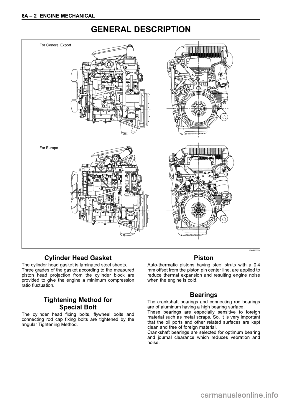
For General Export
For Europe
F06R200004