torque OPEL FRONTERA 1998 Repair Manual
[x] Cancel search | Manufacturer: OPEL, Model Year: 1998, Model line: FRONTERA, Model: OPEL FRONTERA 1998Pages: 6000, PDF Size: 97 MB
Page 715 of 6000
4C–49 DRIVE SHAFT SYSTEM
Removal
1. Jack up the vehicle and support it on the chassis
stands.
2. Gear shift lever should be placed in neutral position
and parking brake released.
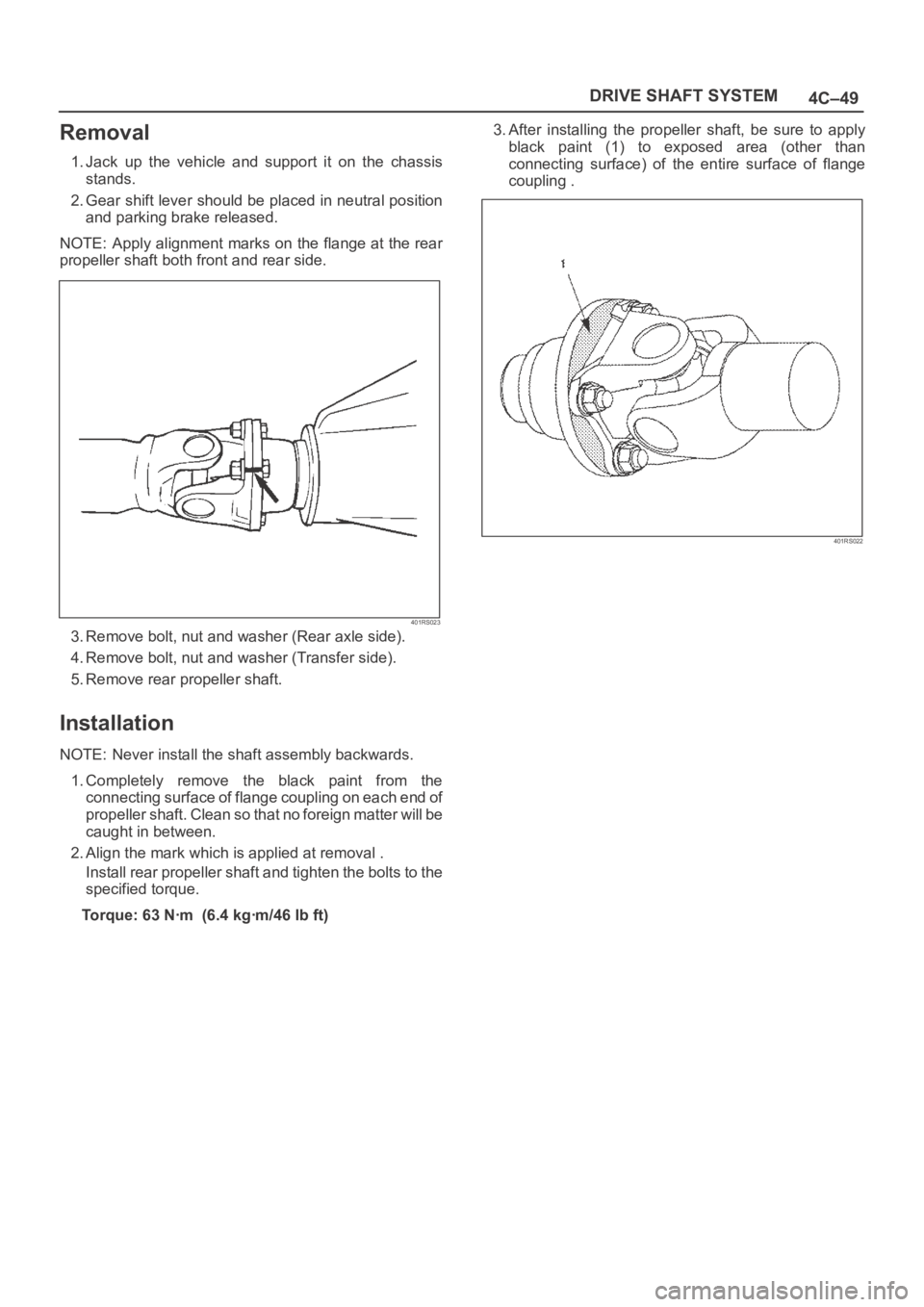
NOTE: Apply alignment marks on the flange at the rear
propeller shaft both front and rear side.
401RS023
3. Remove bolt, nut and washer (Rear axle side).
4. Remove bolt, nut and washer (Transfer side).
5. Remove rear propeller shaft.
Installation
NOTE: Never install the shaft assembly backwards.
1. Completely remove the black paint from the
connecting surface of flange coupling on each end of
propeller shaft. Clean so that no foreign matter will be
caught in between.
2. Align the mark which is applied at removal .
Install rear propeller shaft and tighten the bolts to the
specified torque.
Torque: 63 Nꞏm (6.4 kgꞏm/46 lb ft)3. After installing the propeller shaft, be sure to apply
black paint (1) to exposed area (other than
connecting surface) of the entire surface of flange
coupling .
401RS022
Page 721 of 6000
4C–55 DRIVE SHAFT SYSTEM
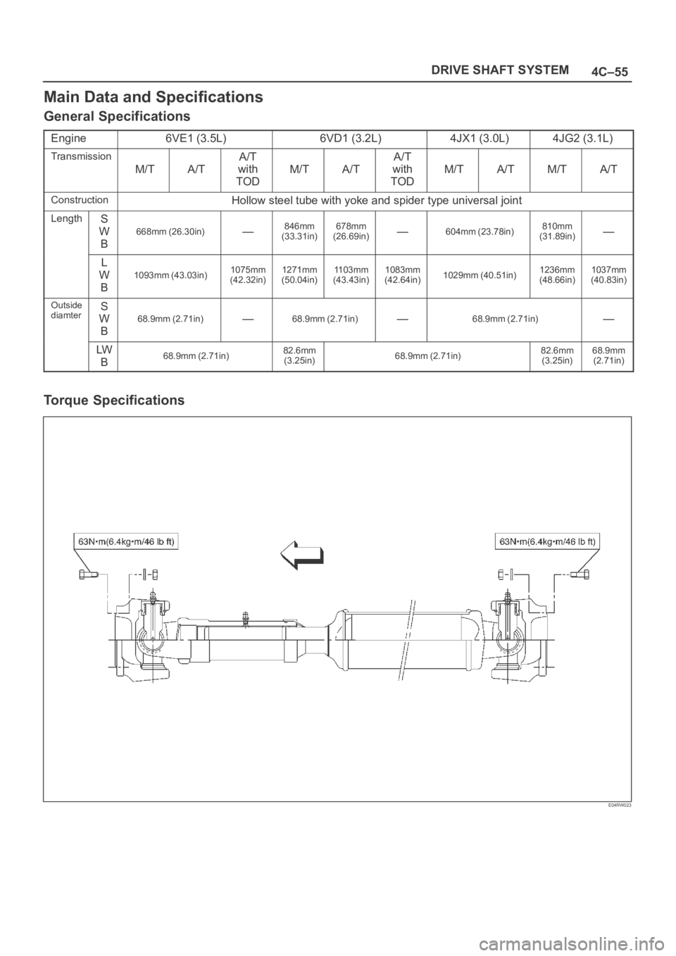
Main Data and Specifications
General Specifications
Engine6VE1 (3.5L)6VD1 (3.2L)4JX1 (3.0L)4JG2 (3.1L)
Transmission
M/TA/T
A/T
with
TOD
M/TA/T
A/T
with
TOD
M/TA/TM/TA/T
ConstructionHollow steel tube with yoke and spider type universal joint
LengthS
W
B
668mm (26.30in)—846mm
(33.31in)678mm
(26.69in)—604mm (23.78in)810mm
(31.89in)—
L
W
B
1093mm (43.03in)1075mm
(42.32in)1271mm
(50.04in)1103mm
(43.43in)1083mm
(42.64in)1029mm (40.51in)1236mm
(48.66in)1037mm
(40.83in)
Outside
diamterS
W
B
68.9mm (2.71in)—68.9mm (2.71in)—68.9mm (2.71in)—
LW
B68.9mm (2.71in)82.6mm
(3.25in)68.9mm (2.71in)82.6mm
(3.25in)68.9mm
(2.71in)
Torque Specifications
E04RW023
Page 722 of 6000

TRANSFER CASE (STANDARD TYPE)
4D1–1
DRIVELINE/AXLE
TRANSFER CASE (STANDARD TYPE)
CONTENTS
Service Precaution 4D1–1. . . . . . . . . . . . . . . . . . . . . .
General Description 4D1–2. . . . . . . . . . . . . . . . . . . . .
Transfer Rear Oil Seal 4D1–8. . . . . . . . . . . . . . . . . . .
Removal 4D1–8. . . . . . . . . . . . . . . . . . . . . . . . . . . . .
Installation 4D1–8. . . . . . . . . . . . . . . . . . . . . . . . . . . .
Transfer Case Assembly 4D1–9. . . . . . . . . . . . . . . . .
Removal 4D1–9. . . . . . . . . . . . . . . . . . . . . . . . . . . . .
Installation 4D1–10. . . . . . . . . . . . . . . . . . . . . . . . . . . .
Transfer Rear Cover Assembly
(4WD Switch Model) 4D1–11. . . . . . . . . . . . . . . . . . . .
Transfer Rear Cover Assembly and
Associated Parts 4D1–11. . . . . . . . . . . . . . . . . . . . . .
Removal 4D1–12. . . . . . . . . . . . . . . . . . . . . . . . . . . . .
Installation 4D1–13. . . . . . . . . . . . . . . . . . . . . . . . . . . .
Disassembly 4D1–16. . . . . . . . . . . . . . . . . . . . . . . . . .
Inspection and Repair 4D1–17. . . . . . . . . . . . . . . . . .
Reassembly 4D1–17. . . . . . . . . . . . . . . . . . . . . . . . . .
Transfer Rear Cover Assembly
(Except 4WD Switch Model) 4D1–19. . . . . . . . . . . . . . Transfer Rear Cover Assembly and
Associated Parts 4D1–19. . . . . . . . . . . . . . . . . . . . . .
Removal 4D1–20. . . . . . . . . . . . . . . . . . . . . . . . . . . . .
Installation 4D1–20. . . . . . . . . . . . . . . . . . . . . . . . . . . .
Disassembly 4D1–23. . . . . . . . . . . . . . . . . . . . . . . . . .
Inspection and Repair 4D1–24. . . . . . . . . . . . . . . . . .
Reassembly 4D1–24. . . . . . . . . . . . . . . . . . . . . . . . . .
Detent, Shift Arm, and Interlock Pin 4D1–26. . . . . . . .
Disassembled View 4D1–26. . . . . . . . . . . . . . . . . . . .
Disassembly 4D1–26. . . . . . . . . . . . . . . . . . . . . . . . . .
Inspection and Repair 4D1–28. . . . . . . . . . . . . . . . . .
Reassembly 4D1–28. . . . . . . . . . . . . . . . . . . . . . . . . .
Transfer Case Assembly 4D1–30. . . . . . . . . . . . . . . . .
Disassembled View 4D1–30. . . . . . . . . . . . . . . . . . . .
Disassembly 4D1–31. . . . . . . . . . . . . . . . . . . . . . . . . .
Inspection and Repair 4D1–33. . . . . . . . . . . . . . . . . .
Reassembly 4D1–37. . . . . . . . . . . . . . . . . . . . . . . . . .
Main Data and Specifications 4D1–43. . . . . . . . . . . . .
Special Tools 4D1–46. . . . . . . . . . . . . . . . . . . . . . . . . . .
Service Precaution
WARNING: THIS VEHICLE HAS A SUPPLEMENTAL
RESTRAINT SYSTEM (SRS). REFER TO THE SRS
COMPONENT AND WIRING LOCATION VIEW IN
ORDER TO DETERMINE WHETHER YOU ARE
PERFORMING SERVICE ON OR NEAR THE SRS
COMPONENTS OR THE SRS WIRING. WHEN YOU
ARE PERFORMING SERVICE ON OR NEAR THE SRS
COMPONENTS OR THE SRS WIRING, REFER TO
THE SRS SERVICE INFORMATION. FAILURE TO
FOLLOW WARNINGS COULD RESULT IN POSSIBLE
AIR BAG DEPLOYMENT, PERSONAL INJURY, OR
OTHERWISE UNNEEDED SRS SYSTEM REPAIRS.
CAUTION: Always use the correct fastener in the
proper location. When you replace a fastener, use
ONLY the exact part number for that application.
ISUZU will call out those fasteners that require a
replacement after removal. ISUZU will also call out
the fasteners that require thread lockers or thread
sealant. UNLESS OTHERWISE SPECIFIED, do not
use supplemental coatings (Paints, greases, or other
corrosion inhibitors) on threaded fasteners or
fastener joint interfaces. Generally, such coatings
adversely affect the fastener torque and the joint
clamping force, and may damage the fastener. When
you install fasteners, use the correct tightening
sequence and specifications. Following these
instructions can help you avoid damage to parts and
systems.
Page 729 of 6000
4D1–8
TRANSFER CASE (STANDARD TYPE)
Transfer Rear Oil Seal
Removal
1. Disconnect the rear propeller shaft from the transfer
case side.
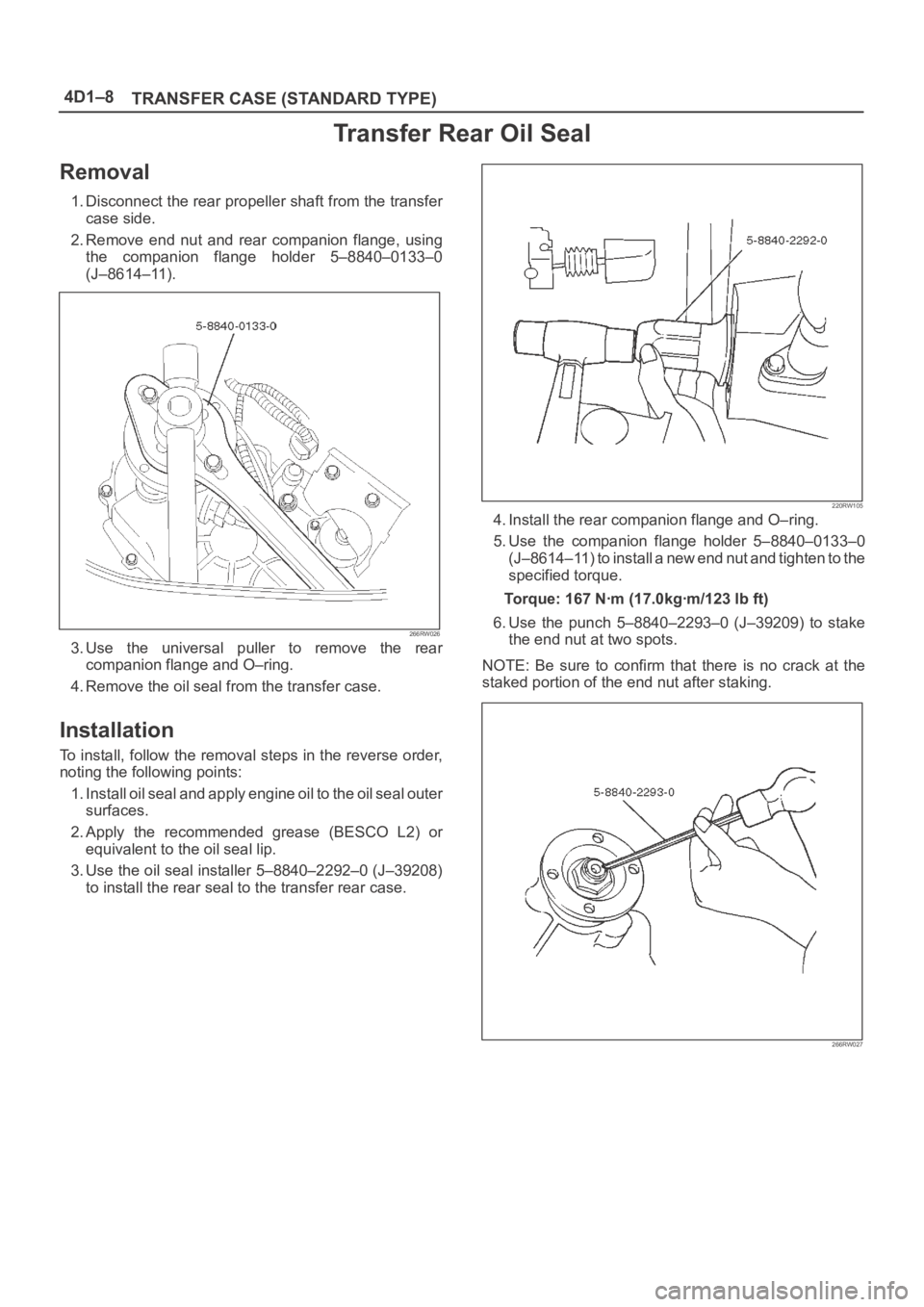
2. Remove end nut and rear companion flange, using
the companion flange holder 5–8840–0133–0
(J–8614–11).
266RW026
3. Use the universal puller to remove the rear
companion flange and O–ring.
4. Remove the oil seal from the transfer case.
Installation
To install, follow the removal steps in the reverse order,
noting the following points:
1. Install oil seal and apply engine oil to the oil seal outer
surfaces.
2. Apply the recommended grease (BESCO L2) or
equivalent to the oil seal lip.
3. Use the oil seal installer 5–8840–2292–0 (J–39208)
to install the rear seal to the transfer rear case.
220RW105
4. Install the rear companion flange and O–ring.
5. Use the companion flange holder 5–8840–0133–0
(J–8614–11) to install a new end nut and tighten to the
specified torque.
Torque: 167 Nꞏm (17.0kgꞏm/123 lb ft)
6. Use the punch 5–8840–2293–0 (J–39209) to stake
the end nut at two spots.
NOTE: Be sure to confirm that there is no crack at the
staked portion of the end nut after staking.
266RW027
Page 730 of 6000
TRANSFER CASE (STANDARD TYPE)
4D1–9
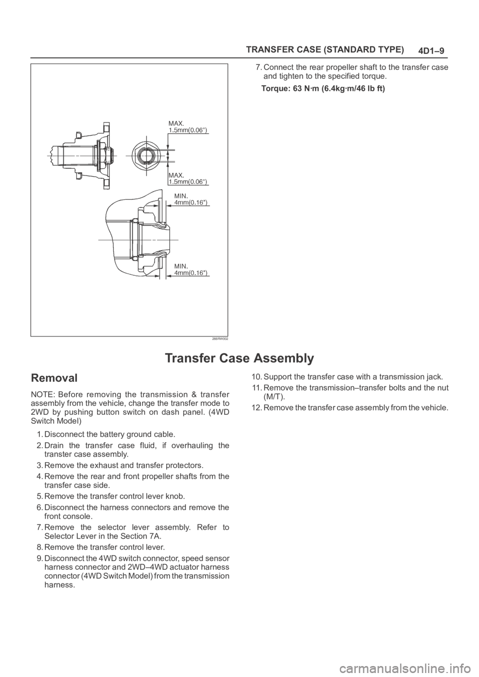
266RW002
7. Connect the rear propeller shaft to the transfer case
and tighten to the specified torque.
Torque: 63 Nꞏm (6.4kgꞏm/46 lb ft)
Transfer Case Assembly
Removal
NOTE: Before removing the transmission & transfer
assembly from the vehicle, change the transfer mode to
2WD by pushing button switch on dash panel. (4WD
Switch Model)
1. Disconnect the battery ground cable.
2. Drain the transfer case fluid, if overhauling the
transter case assembly.
3. Remove the exhaust and transfer protectors.
4. Remove the rear and front propeller shafts from the
transfer case side.
5. Remove the transfer control lever knob.
6. Disconnect the harness connectors and remove the
front console.
7. Remove the selector lever assembly. Refer to
Selector Lever in the Section 7A.
8. Remove the transfer control lever.
9. Disconnect the 4WD switch connector, speed sensor
harness connector and 2WD–4WD actuator harness
connector (4WD Switch Model) from the transmission
harness.10. Support the transfer case with a transmission jack.
11. Remove the transmission–transfer bolts and the nut
(M/T).
12. Remove the transfer case assembly from the vehicle.
Page 731 of 6000
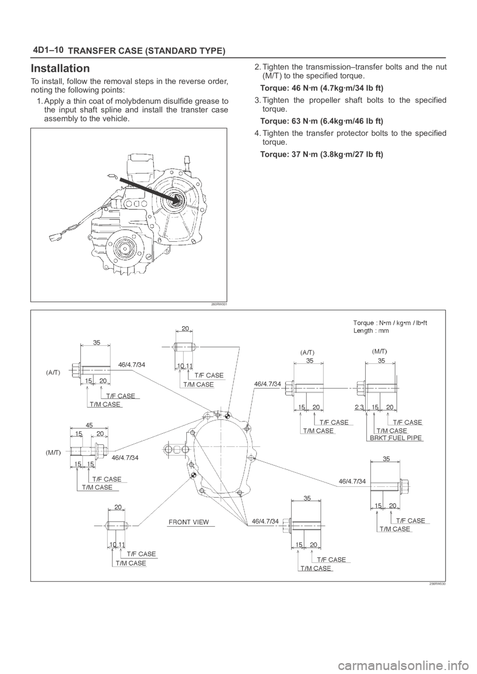
4D1–10
TRANSFER CASE (STANDARD TYPE)
Installation
To install, follow the removal steps in the reverse order,
noting the following points:
1. Apply a thin coat of molybdenum disulfide grease to
the input shaft spline and install the transter case
assembly to the vehicle.
260RW001
2. Tighten the transmission–transfer bolts and the nut
(M/T) to the specified torque.
Torque: 46 Nꞏm (4.7kgꞏm/34 lb ft)
3. Tighten the propeller shaft bolts to the specified
torque.
Torque: 63 Nꞏm (6.4kgꞏm/46 lb ft)
4. Tighten the transfer protector bolts to the specified
torque.
Torque: 37 Nꞏm (3.8kgꞏm/27 lb ft)
256RW030
Page 734 of 6000

TRANSFER CASE (STANDARD TYPE)
4D1–13
10. Offset the actuator assembly.
220RW028
11. Remove the actuator assembly.
220RW029
Legend
(7) Position: 4WD
(8) Mode: 2WD
12. Remove the transfer rear cover assembly from the
transfer case assembly.
Installation
1. Apply the recommended liquid gasket (LOCTITE
17430) or its equivalent to the transfer rear cover
fitting faces.
220RS017
2. Install the transfer rear cover assembly to the transfer
case assembly.
3. Perform the following steps before fitting the transfer
rear case:
1. Shift the high–low shift rod to the 4H side.
2. The cut–away portion of the select rod head (9)
should align with that of the rear case hole’s
stopper (10).
230RW004
4. Tighten the transfer rear case bolts to the specified
torque.
Torque: 37 Nꞏm (3.8kgꞏm/27 lb ft)
5. Shift the 2WD–4WD shift rod (11) to the 4WD side.
Page 735 of 6000

4D1–14
TRANSFER CASE (STANDARD TYPE)
6. Join the rod grooves of 2WD–4WD actuator
assembly (12) and shift rod (11).
220RW030
Legend
(11) Shift Rod: 2WD–4WD (Position: 4WD)
(12) 2WD–4WD Actuator Assembly (Mode: 2WD)
(13) Rear Cover Assembly
7. Push the 2WD–4WD actuator assembly (12) with
2WD–4WD shift rod (11) till the shift rod (11) reaches
the 2WD position.
220RW031
Legend
(14) Position: 2WD
(15) Mode: 2WD
8. Tighten the 2WD–4WD actuator bolts to the specified
torque.
Torque: 19 Nꞏm (1.9kgꞏm/14 lb ft)
9. Install the actuator heat protector.
10. Connect the actuator breather hose to the actuator.11. Install the control box assembly.
Torque: 19 Nꞏm (1.9kgꞏm/14 lb ft)
12. Connect the breather hoses to the control box.
13. Install the rear companion flange and front
companion flange, using the companion flange holder
5–8840–0133–0 (J–8614–11) to tighten the flange
nuts to the transfer case.
262RW067
14. Tighten the new transfer flange nuts to the specified
torque.
To r q u e
Rear companion flange: 167 Nꞏm (17.0kgꞏm/123
lb ft)
Front companion flange: 137 Nꞏm (14.0kgꞏm/101
lb ft)
15. Use the punch 5–8840–2293–0 (J–39209) to stake
the rear companion flange nut at two spots.
266RW027
Page 736 of 6000

TRANSFER CASE (STANDARD TYPE)
4D1–15
266RW002
16. Stake the front companion flange nut at one spot.
NOTE: Be sure to confirm that there is no crack at the
staked portion of the flange nut after staking.
17. Install the O–ring (8) to the speedometer driven gear
bushing (7).
18. Install the driven gear to the speedometer driven gear
bushing (7).
19. Install the speedometer driven gear assembly to the
transfer rear cover.20. Install the plate (6) to the transfer rear case and
tighten to the specified torque.
Torque: 15 Nꞏm (1.5kgꞏm/11 lb ft)
21. Install the speedometer sensor and tighten to the
specified torque.
Torque: 27 Nꞏm (2.8kgꞏm/20 lb ft)
225RW014
Page 741 of 6000

4D1–20
TRANSFER CASE (STANDARD TYPE)
Removal
1. Remove the speedometer sensor.
2. Remove the plate.
3. Remove the speedometer driven gear bushing and
driven gear.
NOTE: Apply a reference mark to the driven gear bushing
before removal.
4. Remove the front companion flange and the rear
companion flange, using the flange companion holder
5–8840–0133–0 (J–8614–11) to remove the end
nuts.
262RW067
NOTE: Use a universal puller to remove the rear
companion flange.
5. Disconnect the transfer breather hose from the
control box.
6. Remove the control box assembly.
7. Remove the transfer rear cover assembly from the
transfer case assembly.
Installation
1. Apply the recommended liquid gasket (LOCTITE
17430) or its equivalent to the transfer rear cover
fitting faces.
220RS017
2. Install the transfer rear cover assembly to the transfer
case assembly.
3. Perform the following steps before fitting the transfer
rear case:
1. Shift the high–low shift rod to the 4H side.
2. Turn the select rod counterclockwise so that the
select block projection may enter into the
2WD–4WD shift block.
3. The cut–away portion of the select rod head (9)
should align with that of the rear case hole’s
stopper (10).
230RW004
4. Tighten the transfer rear case bolts to the specified
torque.
Torque: 37 Nꞏm (3.8kgꞏm/27 lb ft)