torque OPEL FRONTERA 1998 Owner's Guide
[x] Cancel search | Manufacturer: OPEL, Model Year: 1998, Model line: FRONTERA, Model: OPEL FRONTERA 1998Pages: 6000, PDF Size: 97 MB
Page 508 of 6000
DIFFERENTIAL (REAR 244mm)
4A2B–5
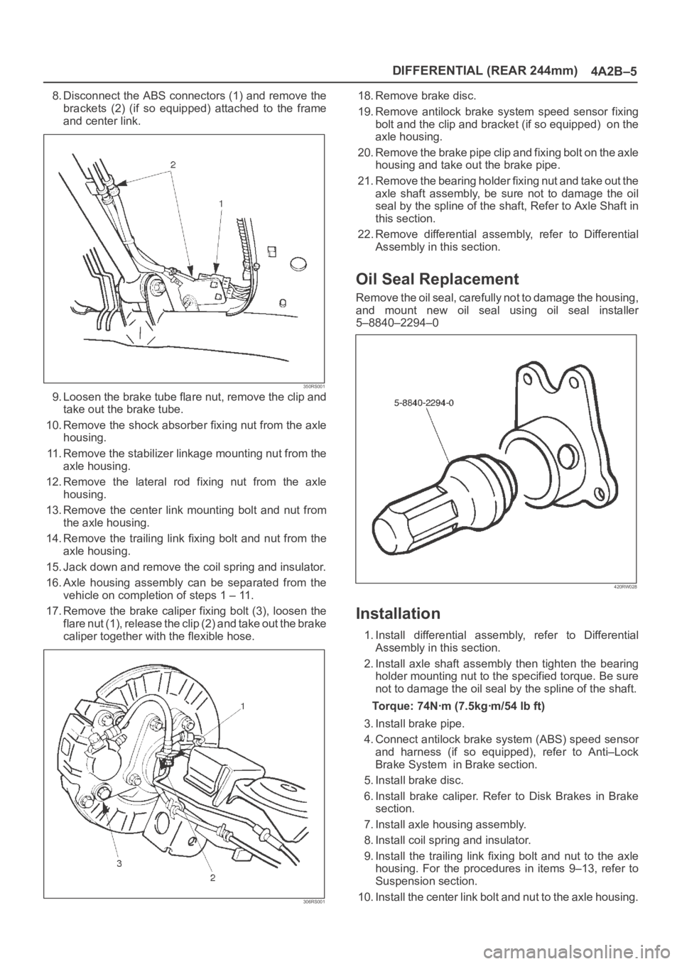
8. Disconnect the ABS connectors (1) and remove the
brackets (2) (if so equipped) attached to the frame
and center link.
350RS001
9. Loosen the brake tube flare nut, remove the clip and
take out the brake tube.
10. Remove the shock absorber fixing nut from the axle
housing.
11. Remove the stabilizer linkage mounting nut from the
axle housing.
12. Remove the lateral rod fixing nut from the axle
housing.
13. Remove the center link mounting bolt and nut from
the axle housing.
14. Remove the trailing link fixing bolt and nut from the
axle housing.
15. Jack down and remove the coil spring and insulator.
16. Axle housing assembly can be separated from the
vehicle on completion of steps 1 – 11.
17. Remove the brake caliper fixing bolt (3), loosen the
flare nut (1), release the clip (2) and take out the brake
caliper together with the flexible hose.
306RS001
18. Remove brake disc.
19. Remove antilock brake system speed sensor fixing
bolt and the clip and bracket (if so equipped) on the
axle housing.
20. Remove the brake pipe clip and fixing bolt on the axle
housing and take out the brake pipe.
21. Remove the bearing holder fixing nut and take out the
axle shaft assembly, be sure not to damage the oil
seal by the spline of the shaft, Refer to Axle Shaft in
this section.
22. Remove differential assembly, refer to Differential
Assembly in this section.
Oil Seal Replacement
Remove the oil seal, carefully not to damage the housing,
and mount new oil seal using oil seal installer
5–8840–2294–0
420RW028
Installation
1. Install differential assembly, refer to Differential
Assembly in this section.
2. Install axle shaft assembly then tighten the bearing
holder mounting nut to the specified torque. Be sure
not to damage the oil seal by the spline of the shaft.
Torque: 74Nꞏm (7.5kgꞏm/54 lb ft)
3. Install brake pipe.
4. Connect antilock brake system (ABS) speed sensor
and harness (if so equipped), refer to Anti–Lock
Brake System in Brake section.
5. Install brake disc.
6. Install brake caliper. Refer to Disk Brakes in Brake
section.
7. Install axle housing assembly.
8. Install coil spring and insulator.
9. Install the trailing link fixing bolt and nut to the axle
housing. For the procedures in items 9–13, refer to
Suspension section.
10. Install the center link bolt and nut to the axle housing.
Page 512 of 6000
DIFFERENTIAL (REAR 244mm)
4A2B–9
Installation
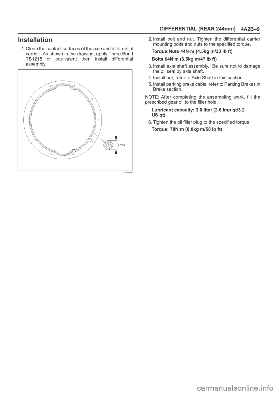
1. Clean the contact surfaces of the axle and differential
carrier. As shown in the drawing, apply Three Bond
TB1215 or equivalent then install differential
assembly.
425RS006
2. Install bolt and nut. Tighten the differential carrier
mounting bolts and nuts to the specified torque.
Torque:Nuts 44Nꞏm (4.5kgꞏm/33 lb ft)
Bolts 64Nꞏm (6.5kgꞏm/47 lb ft)
3. Install axle shaft assembly. Be sure not to damage
the oil seal by axle shaft.
4. Install nut, refer to Axle Shaft in this section.
5. Install parking brake cable, refer to Parking Brakes in
Brake section.
NOTE: After completing the assembling work, fill the
prescribed gear oil to the filler hole.
Lubricant capacity: 3.0 liter (2.6 Imp qt/3.2
US qt)
6. Tighten the oil filler plug to the specified torque.
Torque: 78Nꞏm (8.0kgꞏm/58 lb ft)
Page 516 of 6000
DIFFERENTIAL (REAR 244mm)
4A2B–13
Reassembly
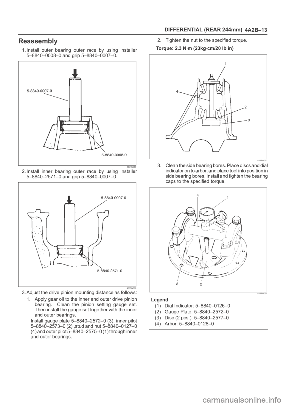
1. Install outer bearing outer race by using installer
5–8840–0008–0 and grip 5–8840–0007–0.
425RW059
2. Install inner bearing outer race by using installer
5–8840–2571–0 and grip 5–8840–0007–0.
425RW060
3. Adjust the drive pinion mounting distance as follows:
1. Apply gear oil to the inner and outer drive pinion
bearing. Clean the pinion setting gauge set.
Then install the gauge set together with the inner
and outer bearings.
Install gauge plate 5–8840–2572–0 (3), inner pilot
5–8840–2573–0 (2) ,stud and nut 5–8840–0127–0
(4) and outer pilot 5–8840–2575–0 (1) through inner
and outer bearings.2. Tighten the nut to the specified torque.
Torque: 2.3 Nꞏm (23kgꞏcm/20 lb in)
425RW030
3. Clean the side bearing bores. Place discs and dial
indicator on to arbor, and place tool into position in
side bearing bores. Install and tighten the bearing
caps to the specified torque.
425RW031
Legend
(1) Dial Indicator: 5–8840–0126–0
(2) Gauge Plate: 5–8840–2572–0
(3) Disc (2 pcs.): 5–8840–2577–0
(4) Arbor: 5–8840–0128–0
Page 519 of 6000
4A2B–16DIFFERENTIAL (REAR 244mm)
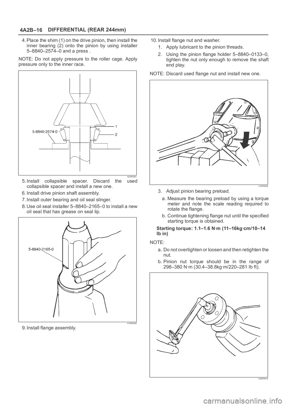
4. Place the shim (1) on the drive pinion, then install the
inner bearing (2) onto the pinion by using installer
5–8840–2574–0 and a press .
NOTE: Do not apply pressure to the roller cage. Apply
pressure only to the inner race.
425RW061
5. Install collapsible spacer. Discard the used
collapsible spacer and install a new one.
6. Install drive pinion shaft assembly.
7. Install outer bearing and oil seal slinger.
8. Use oil seal installer 5–8840–2165–0 to install a new
oil seal that has grease on seal lip.
415RW029
9. Install flange assembly.10. Install flange nut and washer.
1. Apply lubricant to the pinion threads.
2. Using the pinion flange holder 5–8840–0133–0,
tighten the nut only enough to remove the shaft
end play.
NOTE: Discard used flange nut and install new one.
415RW006
3. Adjust pinion bearing preload.
a. Measure the bearing preload by using a torque
meter and note the scale reading required to
rotate the flange.
b. Continue tightening flange nut until the specified
starting torque is obtained.
Starting torque: 1.1–1.6 Nꞏm (11–16kgꞏcm/10–14
lb in)
NOTE:
a. Do not overtighten or loosen and then retighten the
nut.
b. Pinion nut torque should be in the range of
298–380 Nꞏm (30.4–38.8kgꞏm/220–281 Ib ft).
425RW018
Page 522 of 6000
DIFFERENTIAL (REAR 244mm)
4A2B–19
16. Tighten the bolt to the specified torque.
Torque:108Nꞏm (11.0kgꞏm/80 lb ft)
425RS036
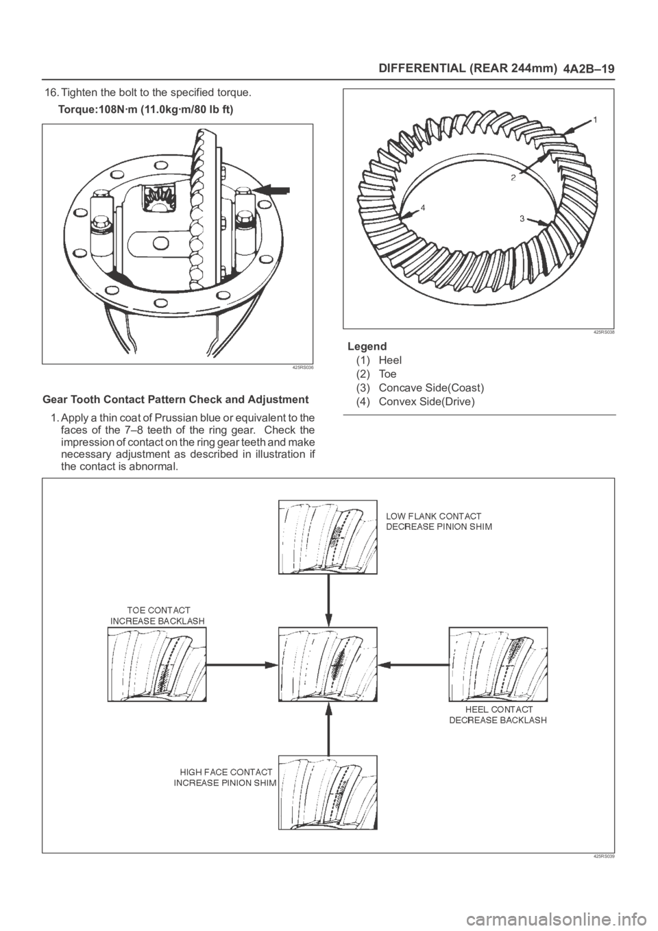
Gear Tooth Contact Pattern Check and Adjustment
1. Apply a thin coat of Prussian blue or equivalent to the
faces of the 7–8 teeth of the ring gear. Check the
impression of contact on the ring gear teeth and make
necessary adjustment as described in illustration if
the contact is abnormal.
425RS038
Legend
(1) Heel
(2) Toe
(3) Concave Side(Coast)
(4) Convex Side(Drive)
425RS039
Page 524 of 6000
DIFFERENTIAL (REAR 244mm)
4A2B–21
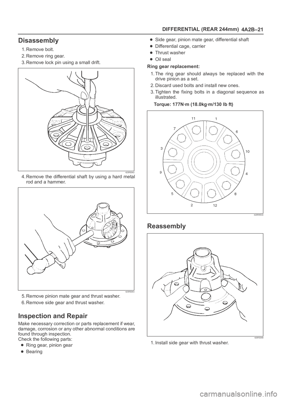
Disassembly
1. Remove bolt.
2. Remove ring gear.
3. Remove lock pin using a small drift.
425RS042
4. Remove the differential shaft by using a hard metal
rod and a hammer.
425RS043
5. Remove pinion mate gear and thrust washer.
6. Remove side gear and thrust washer.
Inspection and Repair
Make necessary correction or parts replacement if wear,
damage, corrosion or any other abnormal conditions are
found through inspection.
Check the following parts:
Ring gear, pinion gear
Bearing
Side gear, pinion mate gear, differential shaft
Differential cage, carrier
Thrust washer
Oil seal
Ring gear replacement:
1. The ring gear should always be replaced with the
drive pinion as a set.
2. Discard used bolts and install new ones.
3. Tighten the fixing bolts in a diagonal sequence as
illustrated.
Torque: 177Nꞏm (18.0kgꞏm/130 lb ft)
425RW033
Reassembly
425RS048
1. Install side gear with thrust washer.
Page 525 of 6000
4A2B–22DIFFERENTIAL (REAR 244mm)
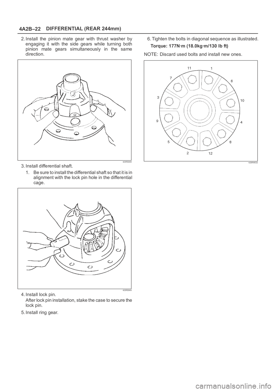
2. Install the pinion mate gear with thrust washer by
engaging it with the side gears while turning both
pinion mate gears simultaneously in the same
direction.
425RS048
3. Install differential shaft.
1 . B e s u r e t o i n s t a l l t h e d i f f e r e n t i a l s h a f t s o t h a t i t i s i n
alignment with the lock pin hole in the differential
cage.
425RS049
4. Install lock pin.
After lock pin installation, stake the case to secure the
lock pin.
5. Install ring gear.6. Tighten the bolts in diagonal sequence as illustrated.
Torque: 177Nꞏm (18.0kgꞏm/130 lb ft)
NOTE: Discard used bolts and install new ones.
425RW033
Page 529 of 6000
4A2B–26DIFFERENTIAL (REAR 244mm)
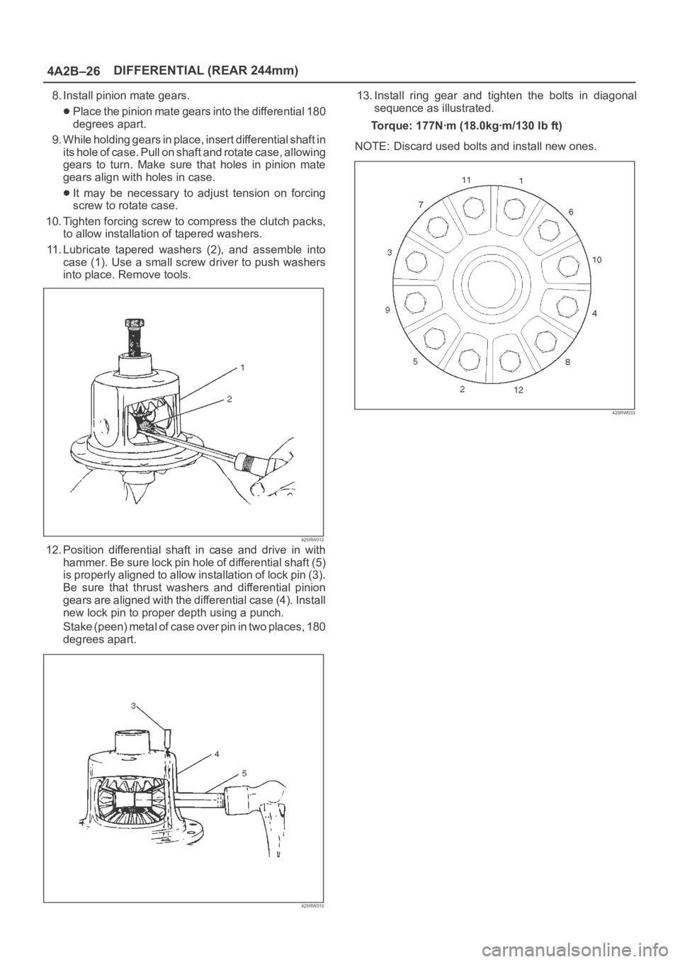
8. Install pinion mate gears.
Place the pinion mate gears into the differential 180
degrees apart.
9. While holding gears in place, insert differential shaft in
its hole of case. Pull on shaft and rotate case, allowing
gears to turn. Make sure that holes in pinion mate
gears align with holes in case.
It may be necessary to adjust tension on forcing
screw to rotate case.
10. Tighten forcing screw to compress the clutch packs,
to allow installation of tapered washers.
11. Lubricate tapered washers (2), and assemble into
case (1). Use a small screw driver to push washers
into place. Remove tools.
425RW012
12. Position differential shaft in case and drive in with
hammer. Be sure lock pin hole of differential shaft (5)
is properly aligned to allow installation of lock pin (3).
Be sure that thrust washers and differential pinion
gears are aligned with the differential case (4). Install
new lock pin to proper depth using a punch.
S t a k e ( p e e n ) m e t a l o f c a s e o v e r p i n i n t w o p l a c e s , 1 8 0
degrees apart.
425RW013
13. Install ring gear and tighten the bolts in diagonal
sequence as illustrated.
Torque: 177Nꞏm (18.0kgꞏm/130 lb ft)
NOTE: Discard used bolts and install new ones.
425RW033
Page 531 of 6000
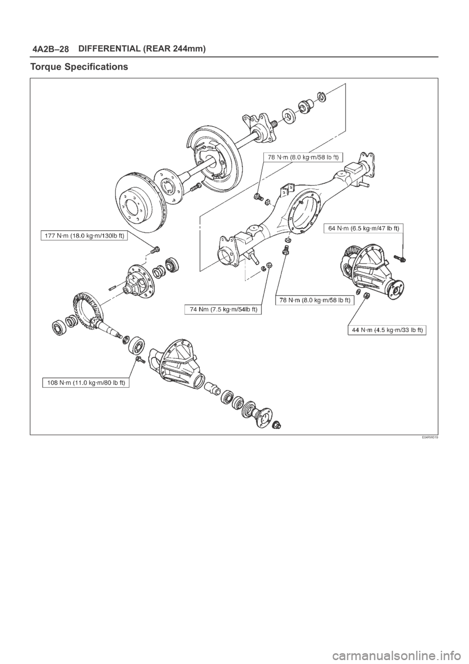
4A2B–28DIFFERENTIAL (REAR 244mm)
Torque Specifications
E04RW019
Page 534 of 6000
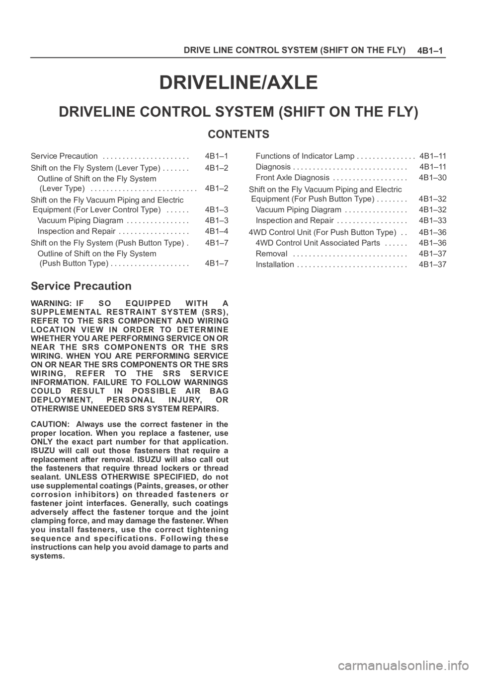
4B1–1 DRIVE LINE CONTROL SYSTEM (SHIFT ON THE FLY)
DRIVELINE/AXLE
DRIVELINE CONTROL SYSTEM (SHIFT ON THE FLY)
CONTENTS
Service Precaution 4B1–1. . . . . . . . . . . . . . . . . . . . . .
Shift on the Fly System (Lever Type) 4B1–2. . . . . . .
Outline of Shift on the Fly System
(Lever Type) 4B1–2. . . . . . . . . . . . . . . . . . . . . . . . . . .
Shift on the Fly Vacuum Piping and Electric
Equipment (For Lever Control Type) 4B1–3. . . . . .
Vacuum Piping Diagram 4B1–3. . . . . . . . . . . . . . . .
Inspection and Repair 4B1–4. . . . . . . . . . . . . . . . . .
Shift on the Fly System (Push Button Type) 4B1–7.
Outline of Shift on the Fly System
(Push Button Type) 4B1–7. . . . . . . . . . . . . . . . . . . . Functions of Indicator Lamp 4B1–11. . . . . . . . . . . . . . .
Diagnosis 4B1–11. . . . . . . . . . . . . . . . . . . . . . . . . . . . .
Front Axle Diagnosis 4B1–30. . . . . . . . . . . . . . . . . . .
Shift on the Fly Vacuum Piping and Electric
Equipment (For Push Button Type) 4B1–32. . . . . . . .
Vacuum Piping Diagram 4B1–32. . . . . . . . . . . . . . . .
Inspection and Repair 4B1–33. . . . . . . . . . . . . . . . . .
4WD Control Unit (For Push Button Type) 4B1–36. .
4WD Control Unit Associated Parts 4B1–36. . . . . .
Removal 4B1–37. . . . . . . . . . . . . . . . . . . . . . . . . . . . .
Installation 4B1–37. . . . . . . . . . . . . . . . . . . . . . . . . . . .
Service Precaution
WARNING: IF SO EQUIPPED WITH A
SUPPLEMENTAL RESTRAINT SYSTEM (SRS),
REFER TO THE SRS COMPONENT AND WIRING
LOCATION VIEW IN ORDER TO DETERMINE
WHETHER YOU ARE PERFORMING SERVICE ON OR
NEAR THE SRS COMPONENTS OR THE SRS
WIRING. WHEN YOU ARE PERFORMING SERVICE
ON OR NEAR THE SRS COMPONENTS OR THE SRS
WIRING, REFER TO THE SRS SERVICE
INFORMATION. FAILURE TO FOLLOW WARNINGS
COULD RESULT IN POSSIBLE AIR BAG
DEPLOYMENT, PERSONAL INJURY, OR
OTHERWISE UNNEEDED SRS SYSTEM REPAIRS.
CAUTION: Always use the correct fastener in the
proper location. When you replace a fastener, use
ONLY the exact part number for that application.
ISUZU will call out those fasteners that require a
replacement after removal. ISUZU will also call out
the fasteners that require thread lockers or thread
sealant. UNLESS OTHERWISE SPECIFIED, do not
use supplemental coatings (Paints, greases, or other
corrosion inhibitors) on threaded fasteners or
fastener joint interfaces. Generally, such coatings
adversely affect the fastener torque and the joint
clamping force, and may damage the fastener. When
you install fasteners, use the correct tightening
sequence and specifications. Following these
instructions can help you avoid damage to parts and
systems.