torque OPEL FRONTERA 1998 Service Manual
[x] Cancel search | Manufacturer: OPEL, Model Year: 1998, Model line: FRONTERA, Model: OPEL FRONTERA 1998Pages: 6000, PDF Size: 97 MB
Page 544 of 6000
4B1–11 DRIVE LINE CONTROL SYSTEM (SHIFT ON THE FLY)
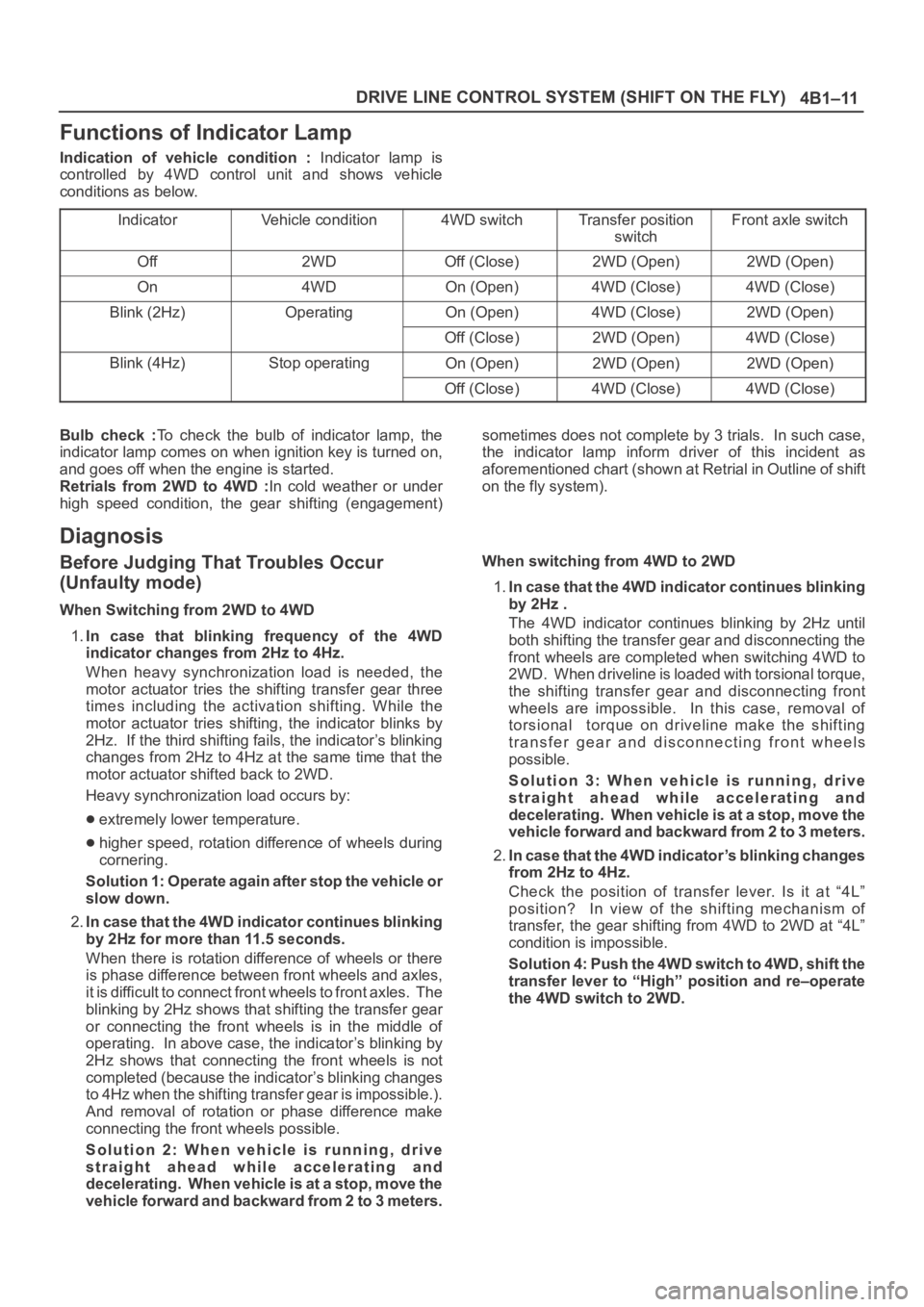
Functions of Indicator Lamp
Indication of vehicle condition : Indicator lamp is
controlled by 4WD control unit and shows vehicle
conditions as below.
Indicator
Vehicle condition4WD switchTransfer position
switchFront axle switch
Off2WDOff (Close)2WD (Open)2WD (Open)
On4WDOn (Open)4WD (Close)4WD (Close)
Blink (2Hz)OperatingOn (Open)4WD (Close)2WD (Open)
Off (Close)2WD (Open)4WD (Close)
Blink (4Hz)Stop operatingOn (Open)2WD (Open)2WD (Open)
Off (Close)4WD (Close)4WD (Close)
Bulb check :To check the bulb of indicator lamp, the
indicator lamp comes on when ignition key is turned on,
and goes off when the engine is started.
Retrials from 2WD to 4WD :In cold weather or under
high speed condition, the gear shifting (engagement)sometimes does not complete by 3 trials. In such case,
the indicator lamp inform driver of this incident as
aforementioned chart (shown at Retrial in Outline of shift
on the fly system).
Diagnosis
Before Judging That Troubles Occur
(Unfaulty mode)
When Switching from 2WD to 4WD
1.In case that blinking frequency of the 4WD
indicator changes from 2Hz to 4Hz.
When heavy synchronization load is needed, the
motor actuator tries the shifting transfer gear three
times including the activation shifting. While the
motor actuator tries shifting, the indicator blinks by
2Hz. If the third shifting fails, the indicator’s blinking
changes from 2Hz to 4Hz at the same time that the
motor actuator shifted back to 2WD.
Heavy synchronization load occurs by:
extremely lower temperature.
higher speed, rotation difference of wheels during
cornering.
Solution 1: Operate again after stop the vehicle or
slow down.
2.In case that the 4WD indicator continues blinking
by 2Hz for more than 11.5 seconds.
When there is rotation difference of wheels or there
is phase difference between front wheels and axles,
it is difficult to connect front wheels to front axles. The
blinking by 2Hz shows that shifting the transfer gear
or connecting the front wheels is in the middle of
operating. In above case, the indicator’s blinking by
2Hz shows that connecting the front wheels is not
completed (because the indicator’s blinking changes
to 4Hz when the shifting transfer gear is impossible.).
And removal of rotation or phase difference make
connecting the front wheels possible.
Solution 2: When vehicle is running, drive
straight ahead while accelerating and
decelerating. When vehicle is at a stop, move the
vehicle forward and backward from 2 to 3 meters.When switching from 4WD to 2WD
1.In case that the 4WD indicator continues blinking
by 2Hz .
The 4WD indicator continues blinking by 2Hz until
both shifting the transfer gear and disconnecting the
front wheels are completed when switching 4WD to
2WD. When driveline is loaded with torsional torque,
the shifting transfer gear and disconnecting front
wheels are impossible. In this case, removal of
torsional torque on driveline make the shifting
transfer gear and disconnecting front wheels
possible.
Solution 3: When vehicle is running, drive
straight ahead while accelerating and
decelerating. When vehicle is at a stop, move the
vehicle forward and backward from 2 to 3 meters.
2.In case that the 4WD indicator’s blinking changes
from 2Hz to 4Hz.
Check the position of transfer lever. Is it at “4L”
position? In view of the shifting mechanism of
transfer, the gear shifting from 4WD to 2WD at “4L”
condition is impossible.
Solution 4: Push the 4WD switch to 4WD, shift the
transfer lever to “High” position and re–operate
the 4WD switch to 2WD.
Page 572 of 6000
4B2–1 DRIVE LINE CONTROL SYSTEM (TOD)
DRIVELINE/AXLE
DRIVELINE CONTROL SYSTEM (TOD)
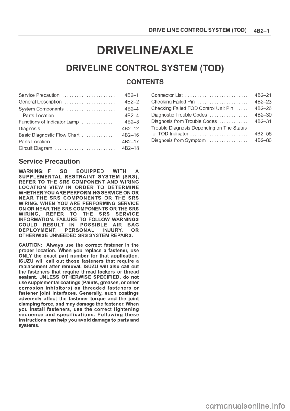
CONTENTS
Service Precaution 4B2–1. . . . . . . . . . . . . . . . . . . . . .
General Description 4B2–2. . . . . . . . . . . . . . . . . . . . .
System Components 4B2–4. . . . . . . . . . . . . . . . . . . .
Parts Location 4B2–4. . . . . . . . . . . . . . . . . . . . . . . .
Functions of Indicator Lamp 4B2–8. . . . . . . . . . . . . .
Diagnosis 4B2–12. . . . . . . . . . . . . . . . . . . . . . . . . . . . . .
Basic Diagnostic Flow Chart 4B2–16. . . . . . . . . . . . . .
Parts Location 4B2–17. . . . . . . . . . . . . . . . . . . . . . . . . .
Circuit Diagram 4B2–18. . . . . . . . . . . . . . . . . . . . . . . . . Connector List 4B2–21. . . . . . . . . . . . . . . . . . . . . . . . . .
Checking Failed Pin 4B2–23. . . . . . . . . . . . . . . . . . . . .
Checking Failed TOD Control Unit Pin 4B2–26. . . . .
Diagnostic Trouble Codes 4B2–30. . . . . . . . . . . . . . . .
Diagnosis from Trouble Codes 4B2–31. . . . . . . . . . . .
Trouble Diagnosis Depending on The Status
of TOD Indicator 4B2–58. . . . . . . . . . . . . . . . . . . . . . . .
Diagnosis from Symptom 4B2–86. . . . . . . . . . . . . . . . .
Service Precaution
WARNING: IF SO EQUIPPED WITH A
SUPPLEMENTAL RESTRAINT SYSTEM (SRS),
REFER TO THE SRS COMPONENT AND WIRING
LOCATION VIEW IN ORDER TO DETERMINE
WHETHER YOU ARE PERFORMING SERVICE ON OR
NEAR THE SRS COMPONENTS OR THE SRS
WIRING. WHEN YOU ARE PERFORMING SERVICE
ON OR NEAR THE SRS COMPONENTS OR THE SRS
WIRING, REFER TO THE SRS SERVICE
INFORMATION. FAILURE TO FOLLOW WARNINGS
COULD RESULT IN POSSIBLE AIR BAG
DEPLOYMENT, PERSONAL INJURY, OR
OTHERWISE UNNEEDED SRS SYSTEM REPAIRS.
CAUTION: Always use the correct fastener in the
proper location. When you replace a fastener, use
ONLY the exact part number for that application.
ISUZU will call out those fasteners that require a
replacement after removal. ISUZU will also call out
the fasteners that require thread lockers or thread
sealant. UNLESS OTHERWISE SPECIFIED, do not
use supplemental coatings (Paints, greases, or other
corrosion inhibitors) on threaded fasteners or
fastener joint interfaces. Generally, such coatings
adversely affect the fastener torque and the joint
clamping force, and may damage the fastener. When
you install fasteners, use the correct tightening
sequence and specifications. Following these
instructions can help you avoid damage to parts and
systems.
Page 573 of 6000
DRIVE LINE CONTROL SYSTEM (TOD) 4B2–2
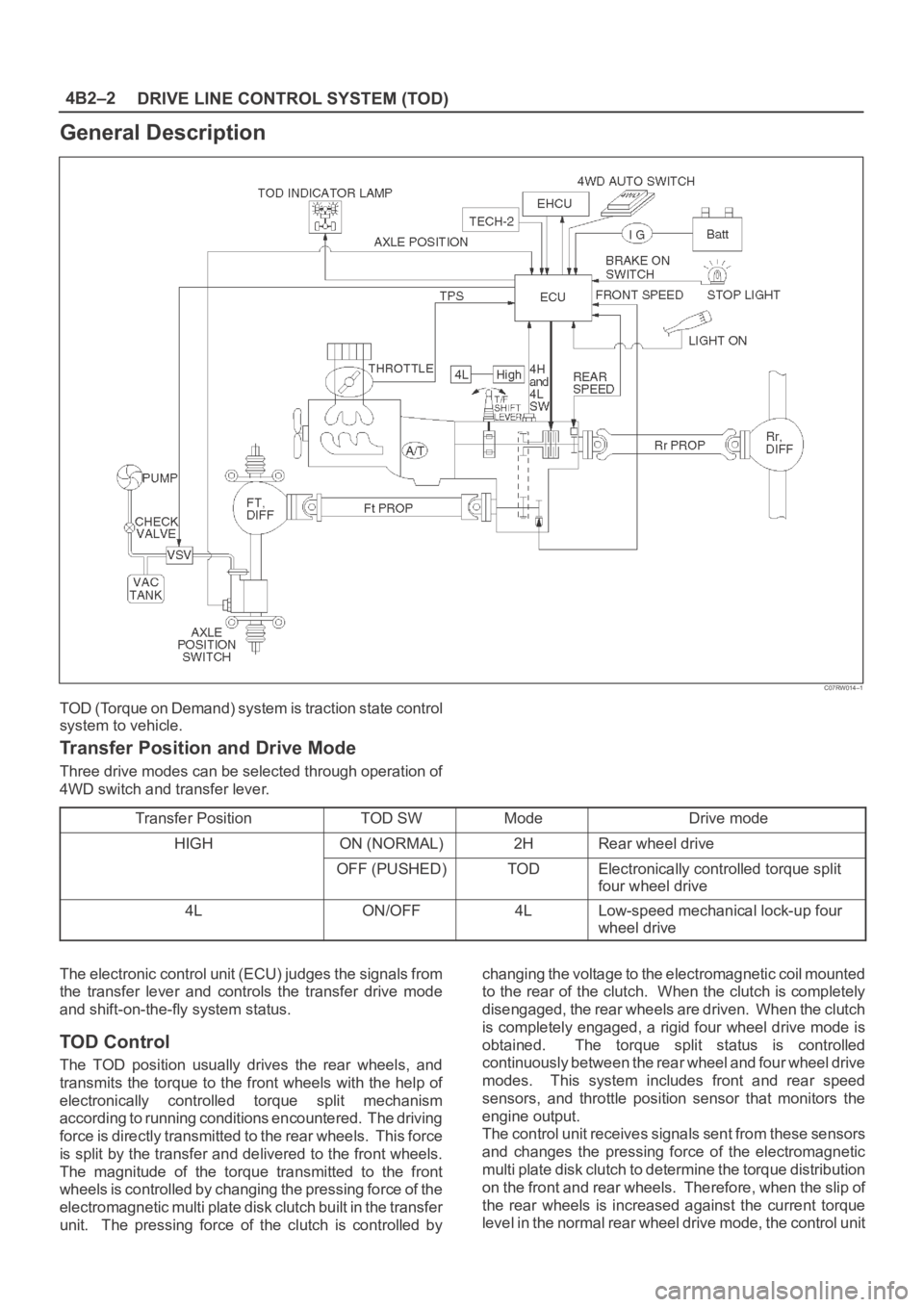
General Description
C07RW014–1
TOD (Torque on Demand) system is traction state control
system to vehicle.
Transfer Position and Drive Mode
Three drive modes can be selected through operation of
4WD switch and transfer lever.
Transfer Position
TOD SWModeDrive mode
HIGHON (NORMAL)2HRear wheel drive
OFF (PUSHED)TODElectronically controlled torque split
four wheel drive
4LON/OFF4LLow-speed mechanical lock-up four
wheel drive
The electronic control unit (ECU) judges the signals from
the transfer lever and controls the transfer drive mode
and shift-on-the-fly system status.
TOD Control
The TOD position usually drives the rear wheels, and
transmits the torque to the front wheels with the help of
electronically controlled torque split mechanism
according to running conditions encountered. The driving
force is directly transmitted to the rear wheels. This force
is split by the transfer and delivered to the front wheels.
The magnitude of the torque transmitted to the front
wheels is controlled by changing the pressing force of the
electromagnetic multi plate disk clutch built in the transfer
unit. The pressing force of the clutch is controlled bychanging the voltage to the electromagnetic coil mounted
to the rear of the clutch. When the clutch is completely
disengaged, the rear wheels are driven. When the clutch
is completely engaged, a rigid four wheel drive mode is
obtained. The torque split status is controlled
continuously between the rear wheel and four wheel drive
modes. This system includes front and rear speed
sensors, and throttle position sensor that monitors the
engine output.
The control unit receives signals sent from these sensors
and changes the pressing force of the electromagnetic
multi plate disk clutch to determine the torque distribution
on the front and rear wheels. Therefore, when the slip of
the rear wheels is increased against the current torque
level in the normal rear wheel drive mode, the control unit
Page 574 of 6000
4B2–3 DRIVE LINE CONTROL SYSTEM (TOD)
detects the slip condition, determines the optimum torque
based on the feedback control logic, and increases the
torque to the front wheels.
The control unit uses the signal from the throttle position
sensor to predict the future vehicle condition and the
intention of the driver with respect to acceleration and
deceleration, and determines the initial torque distribution
using these data and the information from the speed
sensors.
In case of small circle turning in the parking lot, for
example, the control unit minimizes the clutch pressing
force restrict a braking phenomenon. When the ABS
becomes active, the control unit optimizes the clutch
pressing force to ensure stable braking.
TOD Indicator Control
The TOD indicator on the instrument panel informs the
driver of the current working status of the transfer unit.
The information consists of two items: the drive mode
(2H, TOD, 4L, transition) and the torque split status of the
TOD (torque distribution level). The indicator can display
occasional errors and corresponding error codes.
Page 576 of 6000
4B2–5 DRIVE LINE CONTROL SYSTEM (TOD)
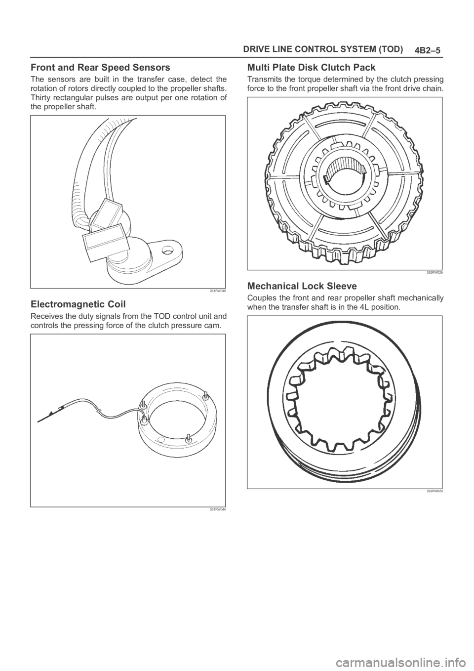
Front and Rear Speed Sensors
The sensors are built in the transfer case, detect the
rotation of rotors directly coupled to the propeller shafts.
Thirty rectangular pulses are output per one rotation of
the propeller shaft.
261RW045
Electromagnetic Coil
Receives the duty signals from the TOD control unit and
controls the pressing force of the clutch pressure cam.
261RW044
Multi Plate Disk Clutch Pack
Transmits the torque determined by the clutch pressing
force to the front propeller shaft via the front drive chain.
262RW029
Mechanical Lock Sleeve
Couples the front and rear propeller shaft mechanically
when the transfer shaft is in the 4L position.
262RW028
Page 661 of 6000
DRIVE LINE CONTROL SYSTEM (TOD) 4B2–90
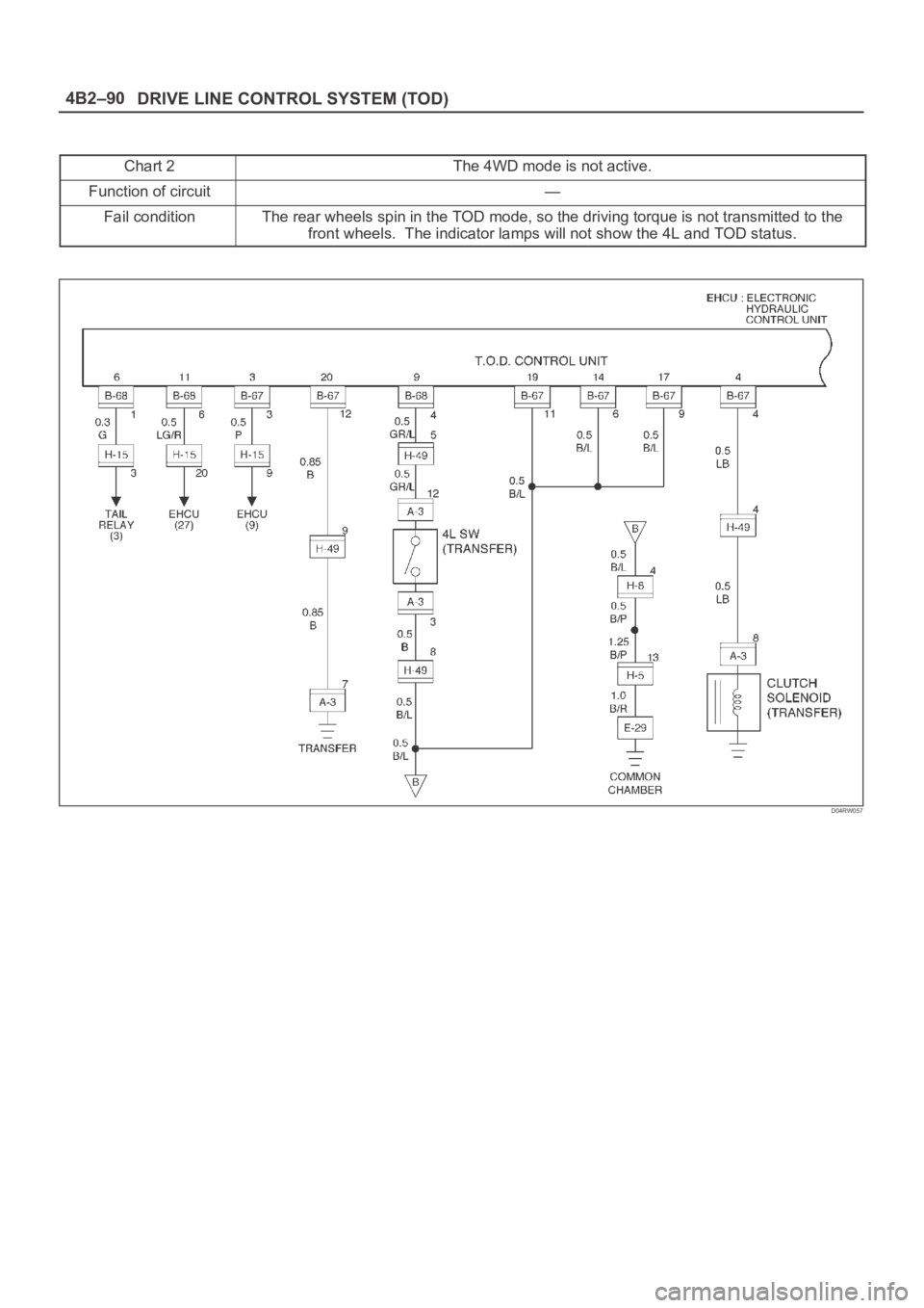
Chart 2The 4WD mode is not active.
Function of circuit—
Fail conditionThe rear wheels spin in the TOD mode, so the driving torque is not transmitted to the
front wheels. The indicator lamps will not show the 4L and TOD status.
D04RW057
Page 668 of 6000
4C–2
DRIVE SHAFT SYSTEM
Service Precaution
WARNING: IF SO EQUIPPED WITH A
SUPPLEMENTAL RESTRAINT SYSTEM (SRS),
REFER TO THE SRS COMPONENT AND WIRING
LOCATION VIEW IN ORDER TO DETERMINE
WHETHER YOU ARE PERFORMING SERVICE ON OR
NEAR THE SRS COMPONENTS OR THE SRS
WIRING. WHEN YOU ARE PERFORMING SERVICE
ON OR NEAR THE SRS COMPONENTS OR THE SRS
WIRING, REFER TO THE SRS SERVICE
INFORMATION. FAILURE TO FOLLOW WARNINGS
COULD RESULT IN POSSIBLE AIR BAG
DEPLOYMENT, PERSONAL INJURY, OR
OTHERWISE UNNEEDED SRS SYSTEM REPAIRS.
CAUTION: Always use the correct fastener in the
proper location. When you replace a fastener, use
ONLY the exact part number for that application.
ISUZU will call out those fasteners that require a
replacement after removal. ISUZU will also call out
the fasteners that require thread lockers or thread
sealant. UNLESS OTHERWISE SPECIFIED , do not
use supplemental coatings (Paints, greases, or other
corrosion inhibitors) on threaded fasteners or
fastener joint interfaces. Generally, such coatings
adversely affect the fastener torque and the joint
clamping force, and may damage the fastener. When
you install fasteners, use the correct tightening
sequence and specifications. Following these
instructions can help you avoid damage to parts and
systems.
General Description
This publication contains essential removal, installation,
adjustment and maintenance procedures.
The front axle utilizes a central disconnect type front
axle/transfer case system.
The drive axles are completely flexible assemblies,
consisting of inner and outer constant velocity (CV) drive
shaft joints connected by an axle shaft.
For description of propeller shaft and universal joint, refer
to Front/Rear Propeller Shaft in this section.
Page 672 of 6000
4C–6
DRIVE SHAFT SYSTEM
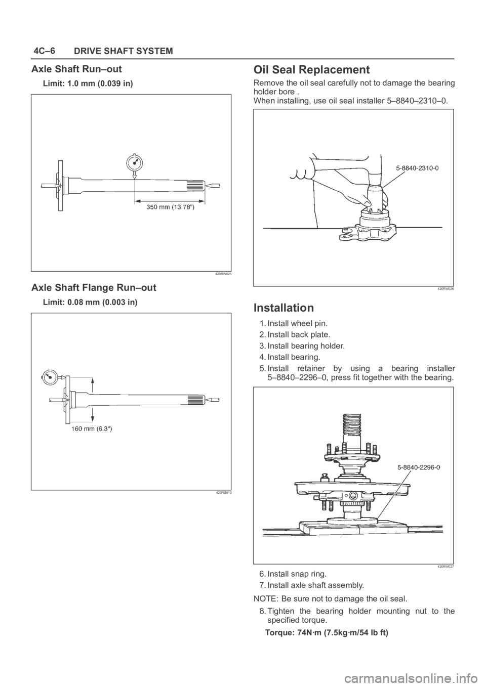
Axle Shaft Run–out
Limit: 1.0 mm (0.039 in)
420RW025
Axle Shaft Flange Run–out
Limit: 0.08 mm (0.003 in)
420RS010
Oil Seal Replacement
Remove the oil seal carefully not to damage the bearing
holder bore .
When installing, use oil seal installer 5–8840–2310–0.
420RW026
Installation
1. Install wheel pin.
2. Install back plate.
3. Install bearing holder.
4. Install bearing.
5. Install retainer by using a bearing installer
5–8840–2296–0, press fit together with the bearing.
420RW027
6. Install snap ring.
7. Install axle shaft assembly.
NOTE: Be sure not to damage the oil seal.
8. Tighten the bearing holder mounting nut to the
specified torque.
Torque: 74Nꞏm (7.5kgꞏm/54 Ib ft)
Page 677 of 6000
4C–11 DRIVE SHAFT SYSTEM
Reassembly
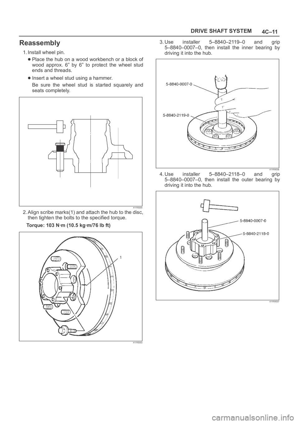
1. Install wheel pin.
Place the hub on a wood workbench or a block of
wood approx. 6” by 6” to protect the wheel stud
ends and threads.
Insert a wheel stud using a hammer.
Be sure the wheel stud is started squarely and
seats completely.
411RS005
2. Align scribe marks(1) and attach the hub to the disc,
then tighten the bolts to the specified torque.
Torque: 103 Nꞏm (10.5 kgꞏm/76 lb ft)
411RS003
3. Use installer 5–8840–2119–0 and grip
5–8840–0007–0, then install the inner bearing by
driving it into the hub.
411RW006
4. Use installer 5–8840–2118–0 and grip
5–8840–0007–0, then install the outer bearing by
driving it into the hub.
411RW007
Page 678 of 6000
4C–12
DRIVE SHAFT SYSTEM
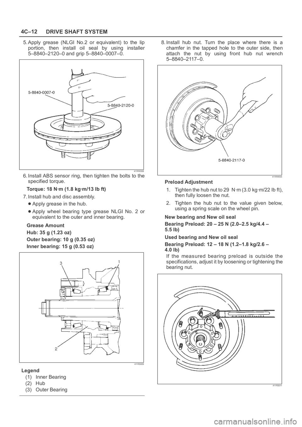
5. Apply grease (NLGI No.2 or equivalent) to the lip
portion, then install oil seal by using installer
5–8840–2120–0 and grip 5–8840–0007–0.
411RW008
6. Install ABS sensor ring, then tighten the bolts to the
specified torque.
Torque: 18 Nꞏm (1.8 kgꞏm/13 lb ft)
7. Install hub and disc assembly.
Apply grease in the hub.
Apply wheel bearing type grease NLGI No. 2 or
equivalent to the outer and inner bearing.
Grease Amount
Hub: 35 g (1.23 oz)
Outer bearing: 10 g (0.35 oz)
Inner bearing: 15 g (0.53 oz)
411RS009
Legend
(1) Inner Bearing
(2) Hub
(3) Outer Bearing
8. Install hub nut. Turn the place where there is a
chamfer in the tapped hole to the outer side, then
attach the nut by using front hub nut wrench
5–8840–2117–0.
411RW005
Preload Adjustment
1. Tighten the hub nut to 29 Nꞏm (3.0 kgꞏm/22 lb ft),
then fully loosen the nut.
2. Tighten the hub nut to the value given below,
using a spring scale on the wheel pin.
New bearing and New oil seal
Bearing Preload: 20 – 25 N (2.0–2.5 kg/4.4 –
5.5 lb)
Used bearing and New oil seal
Bearing Preload: 12 – 18 N (1.2–1.8 kg/2.6 –
4.0 lb)
If the measured bearing preload is outside the
specifications, adjust it by loosening or tightening the
bearing nut.
411RS011