fuse OPEL FRONTERA 1998 Manual Online
[x] Cancel search | Manufacturer: OPEL, Model Year: 1998, Model line: FRONTERA, Model: OPEL FRONTERA 1998Pages: 6000, PDF Size: 97 MB
Page 2275 of 6000

7A1–30
TRANSMISSION CONTROL SYSTEM (4L30–E)
DTC P0705 Transmission Range Switch (Mode Switch) Illegal Position
D07RW031
Circuit Description
The range switch supplies the Powertrain Control
Module (PCM) with information regarding the selector
lever position: P, R, N, D 3, 2 or L. The selector lever
position is indicated by the state of four ON/OFF
contracts. The range switch is located on one side of
the transmission. It is on the transmission manual
shaft and is fixed to the main case.
The range switch is also used to provide the
information P or N to the engine crank wiring. The
engine can be cranked only if connector M–25
terminal 4(H) is connected to terminal 1(E) which is
connected to ground.
The range switch is also used to provide the backup
lamp power in reverse. This is why the range switch is
supplied through a 10A fuse (C–3). This fuse can
burn due to a short circuit in the backup lamp.
This DTC detects when a fuse is open or the range switch
circuit does not work. This is a type “D” DTC.
Conditions For Setting The DTC
Range switch illegal positions met for 5 seconds.
Action Taken When The DTC Sets
Default to D position.
Inhibit torque management.
Maximum line pressure.
The PCM will not illuminate the CHECK TRANS
Lamp.
Conditions For Clearing The DTC
The DTC can be cleared from the PCM history by
using a scan tool.
The DTC will be cleared from history when the vehicle
has achieved 40 warmup cycles without a failure
reported.
The PCM will cancel the DTC default actions when
the fault no longer exists and the ignition is cycled “off”
long enough to power down the PCM.
Diagnostic Aids
Refer to accompanying chart for the normal range
signals and the illegal combinations.
Inspect the wiring for poor electrical connections at
the PCM and at the transmission 8–way connector.
Look for possible bent, backed out, deformed or
damaged terminals. Check for weak terminal tension
as we ll. A lso ch eck fo r a ch af e d w ire th at cou l d s ho r t
to bare metal or other wiring. Inspect for a broken wire
inside the insulation.
When diagnosing for a possible intermittent short or
open condition, move the wiring harness while
observing test equipment for a change.
Page 2276 of 6000
TRANSMISSION CONTROL SYSTEM (4L30–E)7A1–31
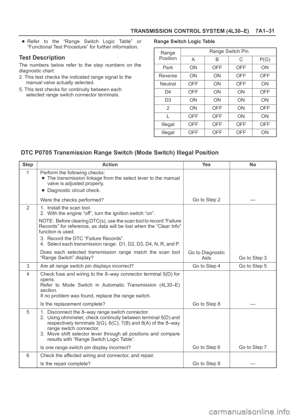
Refer to the “Range Switch Logic Table” or
“Functional Test Procedure” for further information.
Test Description
The numbers below refer to the step numbers on the
diagnostic chart:
2. This test checks the indicated range signal to the
manual valve actually selected.
5. This test checks for continuity between each
selected range switch connector terminals.Range Switch Logic Table
Range
Range Switch Ping
PositionABCP(G)
ParkONOFFOFFON
ReverseONONOFFOFF
NeutralOFFONOFFON
D4OFFONONOFF
D3ONONONON
2ONOFFONOFF
LOFFOFFONON
IllegalOFFOFFOFFOFF
IllegalOFFOFFOFFON
DTC P0705 Transmission Range Switch (Mode Switch) Illegal Position
StepActionYe sNo
1Perform the following checks:
The transmission linkage from the select lever to the manual
valve is adjusted properly.
Diagnostic circuit check.
Were the checks performed?
Go to Step 2—
21. Install the scan tool.
2. With the engine “off”, turn the ignition switch “on”.
NOTE: Before clearing DTC(s), use the scan tool to record “Failure
Records” for reference, as data will be lost when the “Clear Info”
function is used.
3. Record the DTC “Failure Records”.
4. Select each transmission range: D1, D2, D3, D4, N, R, and P.
Does each selected transmission range match the scan tool
“Range Switch” display?
Go to Diagnostic
Aids
Go to Step 3
3Are all range switch pin displays incorrect?Go to Step 4Go to Step 5
4Check fuse and wiring to the 8–way connector terminal 5(D) for
opens.
Refer to Mode Switch in Automatic Transmission (4L30–E)
section.
If no problem was found, replace the range switch.
Is the replacement complete?
Go to Step 8—
51. Disconnect the 8–way range switch connector.
2. Using ohmmeter, check continuity between terminal 5(D) and
respectively terminals 3(G), 6(C), 7(B) and 8(A) of the 8–way
range switch connector.
3. Move shift selector lever through all positions and compare
results with “Range Switch Logic Table”.
Is one range switch pin display incorrect?
Go to Step 6Go to Step 7
6Check the affected wiring and connector, and repair.
Is the repair complete?
Go to Step 8—
Page 2278 of 6000

TRANSMISSION CONTROL SYSTEM (4L30–E)7A1–33
DTC P0706 Transmission Range Switch (Mode Switch) Performance
D07RW031
Circuit Description
The range switch supplies the Powertrain Control
Module (PCM) with information regarding the selector
l e v e r p o s i t i o n : P, R , N , D , 3 , 2 o r L . T h e s e l e c t o r l e v e r
position is indicated by the state of four ON/OFF
contracts. The range switch is located on one side of
the transmission. It is on the transmission manual
shaft and is fixed to the main case.
The range switch is also used to provide the
information P or N to the engine crank wiring. The
engine can be cranked only if connector M–25
terminal 4(H) is connected to terminal 1(E) which is
connected to ground.
The range switch is also used to provide the backup
lamp power in reverse. This is why the mode switch is
supplied through a 10A fuse (C–3). This fuse can
burn due to a shot circuit in the backup lamp.
This DTC detects an invalid state of the range switch
or the range switch circuit by deciphering the range
switch inputs. This is a type “D” DTC.
Conditions For Setting The DTC
This DTC will set if any of the following conditions occurs:
Condition 1 (“R” bad position):
Engine is running.
No output speed DTCP0722, P0723.
Output speed greater then 3,200 RPM.
Range switch indicates “R”.
All conditions met for 4 seconds.
Condition 2 (“P” or “N” bad position):
Engine is running.
No TPS codes.
Engine speed is less than 3,000 RPM.
TP angle is greater than 20%.
Range switch indicates “P” or “N”.
All conditions met for 4 seconds.
Action Taken When The DTC Sets
Default to “D” position.
The PCM will not illuminate the CHECK TRANS
Lamp.
Conditions For Clearing The DTC
The DTC can be cleared from the PCM history by
using a scan tool.
The DTC will be cleared from history when the vehicle
has achieved 40 warmup cycles without a failure
reported.
The PCM will cancel the DTC default actions when
the fault no longer exists and the ignition is cycled “off”
long enough to power down the PCM.
Page 2279 of 6000
7A1–34
TRANSMISSION CONTROL SYSTEM (4L30–E)
Diagnostic Aids
Refer to the accompanying chart for the normal range
signals and the illegal combinations.
Inspect the wiring for poor electrical connections at
the PCM and at the transmission 8–way connector.
Look for possible bent, backed out, deformed or
damaged terminals. Check for weak terminal tension
as well. Also check for a chafed wire that could short
to bare metal or other wiring. Inspect for a broken wire
inside the insulation.
When diagnosing for a possible intermittent short or
open condition, move the wiring harness while
observing test equipment for a change.
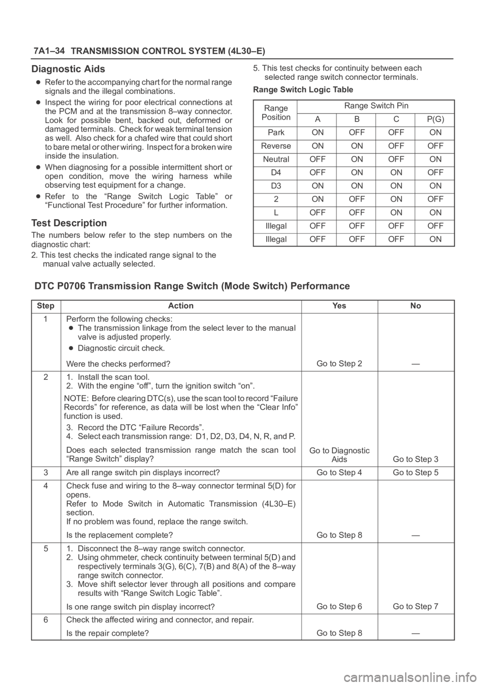
Refer to the “Range Switch Logic Table” or
“Functional Test Procedure” for further information.
Test Description
The numbers below refer to the step numbers on the
diagnostic chart:
2. This test checks the indicated range signal to the
manual valve actually selected.5. This test checks for continuity between each
selected range switch connector terminals.
Range Switch Logic Table
Range
Range Switch Ping
PositionABCP(G)
ParkONOFFOFFON
ReverseONONOFFOFF
NeutralOFFONOFFON
D4OFFONONOFF
D3ONONONON
2ONOFFONOFF
LOFFOFFONON
IllegalOFFOFFOFFOFF
IllegalOFFOFFOFFON
DTC P0706 Transmission Range Switch (Mode Switch) Performance
StepActionYe sNo
1Perform the following checks:
The transmission linkage from the select lever to the manual
valve is adjusted properly.
Diagnostic circuit check.
Were the checks performed?
Go to Step 2—
21. Install the scan tool.
2. With the engine “off”, turn the ignition switch “on”.
NOTE: Before clearing DTC(s), use the scan tool to record “Failure
Records” for reference, as data will be lost when the “Clear Info”
function is used.
3. Record the DTC “Failure Records”.
4. Select each transmission range: D1, D2, D3, D4, N, R, and P.
Does each selected transmission range match the scan tool
“Range Switch” display?
Go to Diagnostic
Aids
Go to Step 3
3Are all range switch pin displays incorrect?Go to Step 4Go to Step 5
4Check fuse and wiring to the 8–way connector terminal 5(D) for
opens.
Refer to Mode Switch in Automatic Transmission (4L30–E)
section.
If no problem was found, replace the range switch.
Is the replacement complete?
Go to Step 8—
51. Disconnect the 8–way range switch connector.
2. Using ohmmeter, check continuity between terminal 5(D) and
respectively terminals 3(G), 6(C), 7(B) and 8(A) of the 8–way
range switch connector.
3. Move shift selector lever through all positions and compare
results with “Range Switch Logic Table”.
Is one range switch pin display incorrect?
Go to Step 6Go to Step 7
6Check the affected wiring and connector, and repair.
Is the repair complete?
Go to Step 8—
Page 2285 of 6000
7A1–40
TRANSMISSION CONTROL SYSTEM (4L30–E)
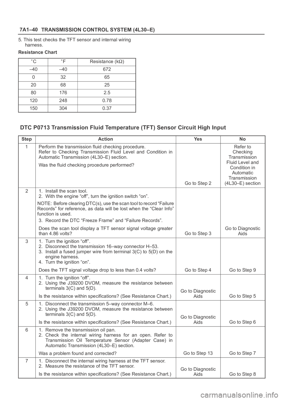
5. This test checks the TFT sensor and internal wiring
harness.
Resistance Chart
CFResistance (k)
–40–40672
03265
206825
801762.5
1202480.78
1503040.37
DTC P0713 Transmission Fluid Temperature (TFT) Sensor Circuit High Input
StepActionYe sNo
1Perform the transmission fluid checking procedure.
Refer to Checking Transmission Fluid Level and Condition in
Automatic Transmission (4L30–E) section.
Was the fluid checking procedure performed?
Go to Step 2
Refer to
Checking
Transmission
Fluid Level and
Condition in
Automatic
Transmission
(4L30–E) section
21. Install the scan tool.
2. With the engine “off”, turn the ignition switch “on”.
NOTE: Before clearing DTC(s), use the scan tool to record “Failure
Records” for reference, as data will be lost when the “Clear Info”
function is used.
3. Record the DTC “Freeze Frame” and “Failure Records”.
Does the scan tool display a TFT sensor signal voltage greater
than 4.86 volts?
Go to Step 3
Go to Diagnostic
Aids
31. Turn the ignition “off”.
2. Disconnect the transmission 16–way connector H–53.
3. Install a fused jumper wire from terminal 3(C) to 5(D) on the
engine harness.
4. Turn the ignition “on”.
Does the TFT signal voltage drop to less than 0.4 volts?
Go to Step 4Go to Step 9
41. Turn the ignition “off”.
2. Using the J39200 DVOM, measure the resistance between
terminals 3(C) and 5(D).
Is the resistance within specifications? (See Resistance Chart.)
Go to Diagnostic
Aids
Go to Step 5
51. Disconnect the transmission 5–way connector M–6.
2. Using the J39200 DVOM, measure the resistance between
terminals 3(C) and 5(D).
Is the resistance within specifications? (See Resistance Chart.)
Go to Diagnostic
Aids
Go to Step 6
61. Remove the transmission oil pan.
2. Check the internal wiring harness for an open. Refer to
Transmission Oil Temperature Sensor (Adapter Case) in
Automatic Transmission (4L30–E) section.
Was a problem found and corrected?
Go to Step 13Go to Step 7
71. Disconnect the internal wiring harness at the TFT sensor.
2. Measure the resistance of the TFT sensor.
Is the resistance within specifications? (See Resistance Chart.)
Go to Diagnostic
Aids
Go to Step 8
Page 2288 of 6000
TRANSMISSION CONTROL SYSTEM (4L30–E)7A1–43
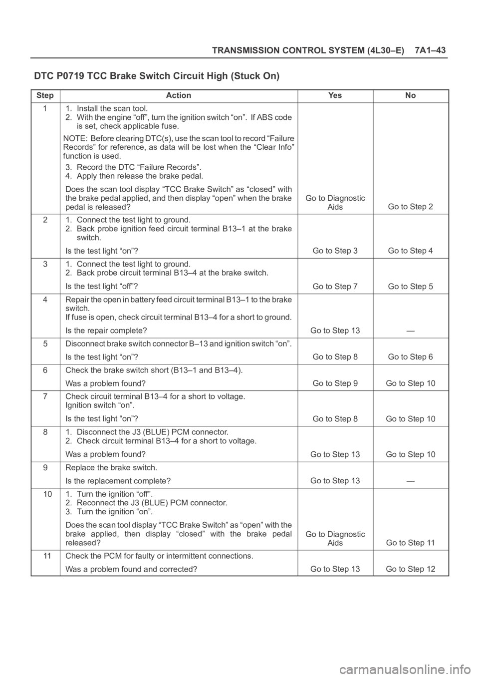
DTC P0719 TCC Brake Switch Circuit High (Stuck On)
StepActionYe sNo
11. Install the scan tool.
2. With the engine “off”, turn the ignition switch “on”. If ABS code
is set, check applicable fuse.
NOTE: Before clearing DTC(s), use the scan tool to record “Failure
Records” for reference, as data will be lost when the “Clear Info”
function is used.
3. Record the DTC “Failure Records”.
4. Apply then release the brake pedal.
Does the scan tool display “TCC Brake Switch” as “closed” with
the brake pedal applied, and then display “open” when the brake
pedal is released?
Go to Diagnostic
Aids
Go to Step 2
21. Connect the test light to ground.
2. Back probe ignition feed circuit terminal B13–1 at the brake
switch.
Is the test light “on”?
Go to Step 3Go to Step 4
31. Connect the test light to ground.
2. Back probe circuit terminal B13–4 at the brake switch.
Is the test light “off”?
Go to Step 7Go to Step 5
4Repair the open in battery feed circuit terminal B13–1 to the brake
switch.
If fuse is open, check circuit terminal B13–4 for a short to ground.
Is the repair complete?
Go to Step 13—
5Disconnect brake switch connector B–13 and ignition switch “on”.
Is the test light “on”?
Go to Step 8Go to Step 6
6Check the brake switch short (B13–1 and B13–4).
Was a problem found?
Go to Step 9Go to Step 10
7Check circuit terminal B13–4 for a short to voltage.
Ignition switch “on”.
Is the test light “on”?
Go to Step 8Go to Step 10
81. Disconnect the J3 (BLUE) PCM connector.
2. Check circuit terminal B13–4 for a short to voltage.
Was a problem found?
Go to Step 13Go to Step 10
9Replace the brake switch.
Is the replacement complete?
Go to Step 13—
101. Turn the ignition “off”.
2. Reconnect the J3 (BLUE) PCM connector.
3. Turn the ignition “on”.
Does the scan tool display “TCC Brake Switch” as “open” with the
brake applied, then display “closed” with the brake pedal
released?
Go to Diagnostic
Aids
Go to Step 11
11Check the PCM for faulty or intermittent connections.
Was a problem found and corrected?
Go to Step 13Go to Step 12
Page 2597 of 6000
The chassis electrical system is a 12–volt system with a
negative ground polarity.
Wire size are appropriate to respective circuits, and
classified by color. (The classification of harnesses by
color is shown on the circuit diagram for ease of harness
identification.)
The wire size is determined by load capacity and the
length of wire required.
The vehicle harnesses are: body harness, chassis
harness, engine room harness, instrument harness,
transmission harness, engine ECGI harness, dome light
harness, door harness, rear body harness, tailgate
harness, SRS harness and battery cables.
The harnesses are protected either by tape or corrugated
tube, depending on harness location.
The circuit for each system consists of the power source,
wire, fuse, relay, switch, load parts and ground, all of
which are shown on the circuit diagram.
In this section, each electrical device is classified by
system.
For major parts shown on the circuit based on the circuit
diagram for each system, a summary, diagnosis of
troubles and inspection procedures are detailed.
Notes for Working on Electrical
Items
Disconnecting the Battery Cable
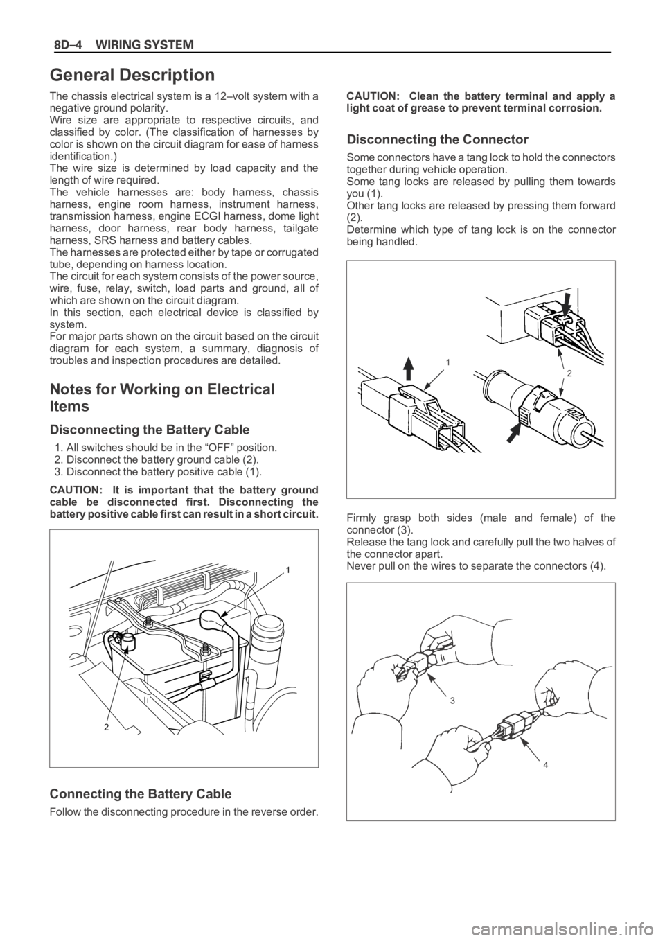
1. All switches should be in the “OFF” position.
2. Disconnect the battery ground cable (2).
3. Disconnect the battery positive cable (1).
CAUTION: It is important that the battery ground
cable be disconnected first. Disconnecting the
battery positive cable first can result in a short circuit.
Connecting the Battery Cable
Follow the disconnecting procedure in the reverse order.CAUTION: Clean the battery terminal and apply a
light coat of grease to prevent terminal corrosion.
Disconnecting the Connector
Some connectors have a tang lock to hold the connectors
together during vehicle operation.
Some tang locks are released by pulling them towards
you (1).
Other tang locks are released by pressing them forward
(2).
Determine which type of tang lock is on the connector
being handled.
Firmly grasp both sides (male and female) of the
connector (3).
Release the tang lock and carefully pull the two halves of
the connector apart.
Never pull on the wires to separate the connectors (4).
2
1
General Description
1
2
3
4
Page 2607 of 6000

Fuse
Fuses are the most common form of circuit protection
used in vehicle wiring. A fuse is a thin piece of wire or strip
of metal encased in a glass or plastic housing. It is wired
in series with the circuit it protects. When there is an
overload of current in a circuit, such as a short of a ground,
the metal strip is designed to burn out and interrupt the
flow of current. This prevents a surge of high current from
reaching and damaging other components in the circuit.
Determine the cause of the overloaded before replacing
the fuse.
The replacement fuse must have the same amperage
specification as the original fuse.
Never replace a blown fuse with a fuse of a different
amperage specification.
Doing so can result in an electrical fire or other serious
circuit damage. A blown fuse is easily identified as shown
in the figure.
Page 2608 of 6000

Fusible Link
The fusible link is primarily used to protect circuits where
high amounts of current flow and where it would not be
practical to use a fuse. For example, the starter circuit.
When a current overload occurs, the fusible link melts
open and interrupts the flow of current so as to prevent
the rest of the wiring harness from burning.
Determine the cause of the overload before replacing the
fusible link. the replacement fusible link must have the
same amperage specification as the original fusible link.
Never replace a blown fusible link with fusible link of a
different amperage specification. Doing so can result in
an electrical fire or other serious circuit damage.
A blown fusible link is easily identified as shown in the
figure.
Fusible Link Specifications
Type Rating Case Color Maximum Circuit Current (A)
Connector 30A Pink 15
Connector 40A Green 20
Bolted 50A Red 25
Bolted 60A Yellow 30
Bolted 80A Black 40
Page 2617 of 6000
12
D08RWA03
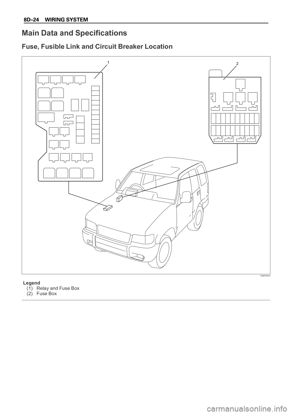
Legend
(1) Relay and Fuse Box
(2) Fuse Box
Main Data and Specifications
Fuse, Fusible Link and Circuit Breaker Location