fuse OPEL FRONTERA 1998 Workshop Manual
[x] Cancel search | Manufacturer: OPEL, Model Year: 1998, Model line: FRONTERA, Model: OPEL FRONTERA 1998Pages: 6000, PDF Size: 97 MB
Page 5620 of 6000

6E–191 4JX1–TC ENGINE DRIVEABILITY AND EMISSIONS
Starter Motor Doesn’t Rotate
StepActionVa l u e ( s )Ye sNo
1DEFINITION:
As starter motor doesn’t rotate, engine is not cranked.
1. Perform a bulletin search.
2. If a bulletin that addresses the symptom is found,
correct the condition as instructed in the bulletin.
Was the bulletin found?
—Verify repairGo to Step 2
2Was a visual/physical check performed?
—Go to Step 3
Go to Visual/
Physical
Check
31. Check battery cord terminal for looseness & poor
contact due to corrosion.
2. Check battery voltage.
3. If a problem is found, repair as necessary.
Was a problem found?
—Verify repairGo to Step 4
41. Check fan belt for looseness & damage.
2. If a problem is found, adjust or replace as
necessary.
Was a problem found?
—Verify repairGo to Step 5
51. Check fuse bull link for disconnection & short.
2. If a problem is found, repair as necessary.
Was a problem found?
—Verify repairGo to Step 6
61. Check generator for mount & damage (Refer to
Engine Mechanical).
2. If a problem is found, repair as necessary.
Was a problem found?
—Verify repairGo to Step 7
71. Check starter SW and starter relay for looseness
and damage.
2. If a problem is found, repair as necessary.
Was a problem found?
—Verify repairGo to Step 8
81. Check starter motor for mount and damage. (Refer
to
Engine Mechanical)
2. If a problem is found, repair as necessary.
Was a problem found?
—Verify repairGo to Step 9
91. Review all diagnostic procedures within this table.
2. If all procedures have been completed and no
malfunctions have been found, review/inspect the
following:
Visual/physical inspection
Te c h 2 d a t a
Freeze Frame data/Failure Records butter
All electrical connections within a suspected
circuit and/or system
3. If a problem is found, repair as necessary.
Was a problem found?
—Verify repair
Contact
Te c h n i c a l
Assistance
Page 5636 of 6000

6E–207 4JX1–TC ENGINE DRIVEABILITY AND EMISSIONS
damage, therefore, it is important to use care when
handling and testing electronic components.
NOTE: To prevent possible Electrostatic Discharge
damage, follow these guidelines:
Do not touch the control module connector pins or
soldered components on the control module circuit
board.
Do not open the replacement part package until the
part is ready to be installed.
Before removing the part from the package, ground
the package to a known good ground on the vehicle.
If the part has been handled while sliding across the
seat, or while sitting down from a standing position, or
while walking a distance, touch a known good ground
before installing the part.
NOTE: To prevent internal ECM damage, the ignition
must be in the “OFF” position in order to disconnect or
reconnect power to the ECM (for example: battery cable,
ECM pigtail, ECM fuse, jumper cables, etc.).
IMPORTANT:When replacing the production ECM
with a service ECM, it is important to transfer the
broadcast code and production ECM number to the
service ECM label. This will allow positive identification of
ECM parts throughout the service life of the vehicle. Do
not record this information on the metal ECM cover.
IMPORTANT:The ignition should always be in the
“OFF” position in order to install or remove the ECM
connectors.
Service of the ECM should normally consist of either re-
placement of the ECM. If the diagnostic procedures call
for the ECM to be replaced, the ECM should be checked
first to ensure it is the correct part. If it is, remove the
faulty ECM and install the new service ECM.
DTC P0601 indicates the check sum error.
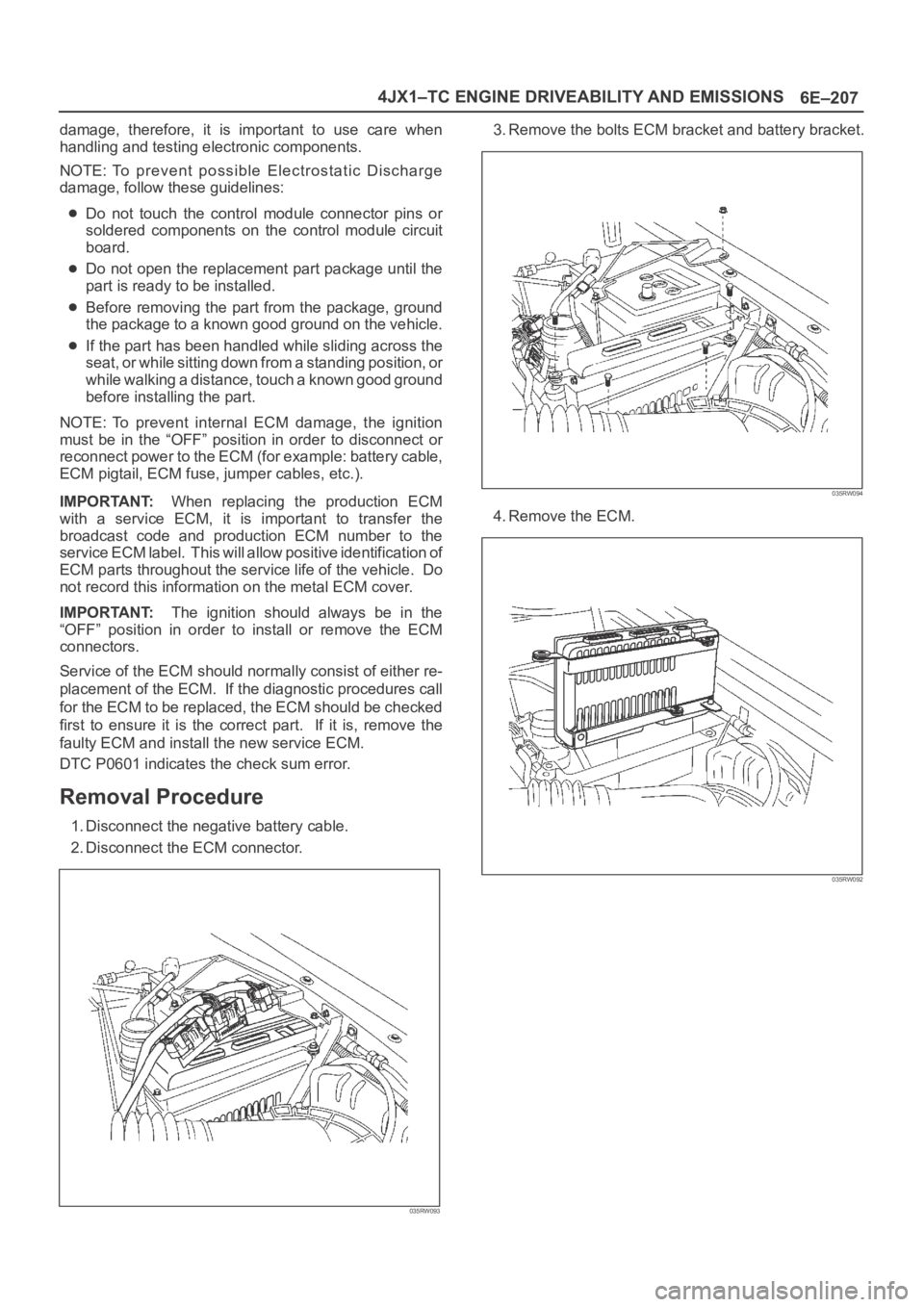
Removal Procedure
1. Disconnect the negative battery cable.
2. Disconnect the ECM connector.
035RW093
3. Remove the bolts ECM bracket and battery bracket.
035RW094
4. Remove the ECM.
035RW092
Page 5646 of 6000

6E–217 4JX1–TC ENGINE DRIVEABILITY AND EMISSIONS
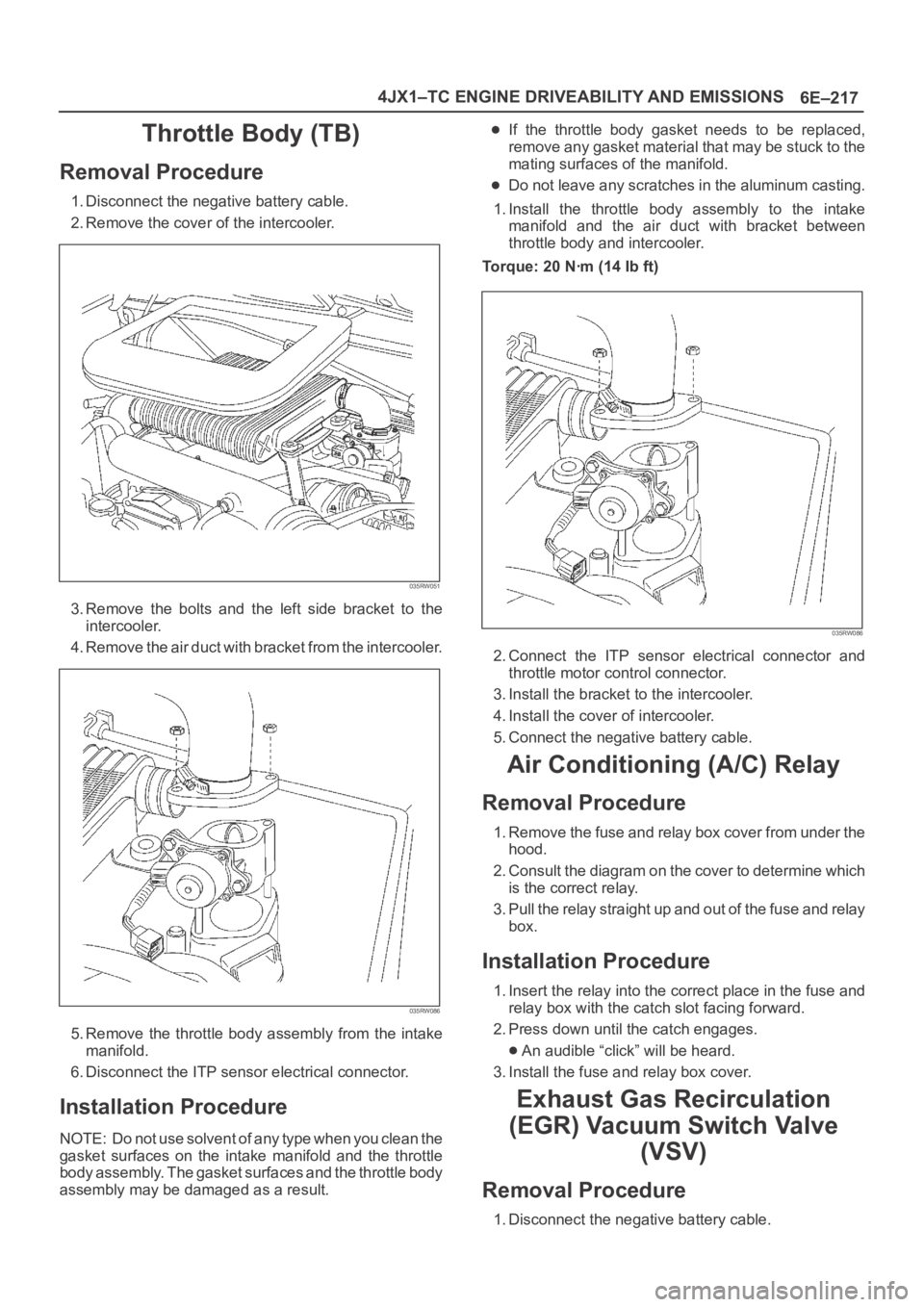
Throttle Body (TB)
Removal Procedure
1. Disconnect the negative battery cable.
2. Remove the cover of the intercooler.
035RW051
3. Remove the bolts and the left side bracket to the
intercooler.
4 . R e m o v e t h e a i r d u c t w i t h b r a c k e t f r o m t h e i n t e r c o o l e r.
035RW086
5. Remove the throttle body assembly from the intake
manifold.
6. Disconnect the ITP sensor electrical connector.
Installation Procedure
NOTE: Do not use solvent of any type when you clean the
gasket surfaces on the intake manifold and the throttle
body assembly. The gasket surfaces and the throttle body
assembly may be damaged as a result.
If the throttle body gasket needs to be replaced,
remove any gasket material that may be stuck to the
mating surfaces of the manifold.
Do not leave any scratches in the aluminum casting.
1. Install the throttle body assembly to the intake
manifold and the air duct with bracket between
throttle body and intercooler.
Torque: 20 Nꞏm (14 Ib ft)
035RW086
2. Connect the ITP sensor electrical connector and
throttle motor control connector.
3. Install the bracket to the intercooler.
4. Install the cover of intercooler.
5. Connect the negative battery cable.
Air Conditioning (A/C) Relay
Removal Procedure
1. Remove the fuse and relay box cover from under the
hood.
2. Consult the diagram on the cover to determine which
is the correct relay.
3. Pull the relay straight up and out of the fuse and relay
box.
Installation Procedure
1. Insert the relay into the correct place in the fuse and
relay box with the catch slot facing forward.
2. Press down until the catch engages.
An audible “click” will be heard.
3. Install the fuse and relay box cover.
Exhaust Gas Recirculation
(EGR) Vacuum Switch Valve
(VSV)
Removal Procedure
1. Disconnect the negative battery cable.
Page 5649 of 6000

6E–220
4JX1–TC ENGINE DRIVEABILITY AND EMISSIONS
Installation Procedure
1. Install the EVRV.
035RW064
2. Connect the EVRV hose and the EVRV connector.
035RW065
3. Connect the negative battery cable.
Wiring and Connectors
Wiring Harness Service
The ECM harness electrically connects the ECM to the
various solenoids, switches and sensors in the vehicle
engine compartment and passenger compartment.
Replace wire harnesses with the proper part number
replacement.
Because of the low amperage and voltage levels utilized
in powertrain control systems, it is essential that all wiring
in environmentally exposed areas be repaired with crimp
and seal splice sleeves.The following wire harness repair information is intended
as a general guideline only. Refer to
Chassis Electrical f o r
all wire harness repair procedures.
Connectors and Terminals
Use care when probing a connector and when replacing
terminals. It is possible to short between opposite
terminals. Damage to components could result. Always
use jumper wires between connectors for circuit
checking. NEVER probe through Weather-Pack seals.
Use an appropriate connector test adapter kit which
contains an assortment of flexible connectors used to
probe terminals during diagnosis. Use an appropriate
fuse remover and test tool for removing a fuse and to
adapt the fuse holder to a meter for diagnosis.
Open circuits are often difficult to locate by sight because
oxidation or terminal misalignment are hidden by the
connectors. Merely wiggling a connector on a sensor, or
in the wiring harness, may temporarily correct the open
circuit. Intermittent problems may also be caused by
oxidized or loose connections.
Be certain of the type of connector/terminal before
making any connector or terminal repair. Weather-Pack
and Com-Pack III terminals look similar, but are serviced
differently.
Wire Harness Repair: Twisted
Shielded Cable
Removal Procedure
1. Remove the outer jacket.
2. Unwrap the aluminum/mylar tape. Do not remove the
mylar.
047
Page 5658 of 6000

6E–229 4JX1–TC ENGINE DRIVEABILITY AND EMISSIONS
Fuse and Relay Panel (Underhood Electrical Center) RHD
035RW109
Page 5659 of 6000

6E–230
4JX1–TC ENGINE DRIVEABILITY AND EMISSIONS
Fuse and Relay Panel (Underhood Electrical Center) LHD
035RW108
Page 5700 of 6000

7A–11 AUTOMATIC TRANSMISSION (4L30–E)
Fluid Condition
FLUID CONDITION
NORMAL*CONTAMINATED
COLORRED OR LIGHT
BROWNBROWNNON–TRANSPARENT
/ PINKBROWN
DRAIN
REQUIRED?NOYESYESYES
CONTAMINA–
TIONNONEVery small amount of
foreign material in
bottom of panContamination by
coolant or other sourceLarge pieces of metal
or other foreign
material in bottom of
pan
CORRECT
LEVEL AND
CONDITION
1. LOW LEVEL:
A. Add fluid to
obtain proper
level & check for
external leaks.
B. Correct cause of
leak.
2. HIGH LEVEL:
– Remove excess
fluid– Remove both pans
– Change filter
– Flush cooler
– Add new fluid
– Check level– Repair/replace
radiator cooler
–Transmission
overhaul required
– Check for:
Damaged plates
and seals
Contaminated
solenoids
– Flush cooler
– Add new fluid
– Check level
–Transmission
overhaul required
– Flush cooler and
cooler lines
– Add new fluid
– Check level
*Fluid should be changed according to maintenance
schedule.
Te s t D r i v i n g
Some 4L30–E automatic transmission complaints will
require a test drive as a part of the diagnostic procedure.
Some codes will not set unless the vehicle is moving. The
purpose of the test drive is to duplicate the customer’s
complaint condition and set a current Powertrain Control
Module (PCM) trouble code. Perform this procedure
before each 4L30–E automatic transmission repair, and
again after repairs are made.
IMPORTANT:
Duplicate the condition under which the customer’s
complaint was observed.
Depending on the complaint, the line pressure gauge
and the scan tool may be required during the test
drive.
During the test drive, it is important to record all
necessary data from the areas being monitored, for
use in diagnosis. Also listen for and note any unusual
noises.
The following procedure should be used to test drive
4L30–E automatic transmission complaint vehicles:
1. Turn the ignition ON without starting the engine.
Check that the “CHECK TRANS” lamp comes on for
approximately 2 seconds and then goes out and
remains out.
If the lamp is flashing, GOTO Check Trans Indicator
in Transmission Control System (4L30–E) section.
If no serial data is present, GOTO OBD System
Check. Refer to Driveability and Emissions in
Engine section.
If the lamp stays ON or stays OFF, GOTO “Check
Trans” Check in Transmission Control System
(4L30–E) section.
2. Drive the vehicle. During the test drive, be sure that
the transmission achieves normal operating
temperature (approx. 20 minutes).
Allow the transmission to go through all of its gear
ranges, checking shift timing and firmness. Duplicate
the owner’s complaint condition as closely as
possible during the test drive.
3. If, during the test drive, the “CHECK TRANS” lamp
comes on, use the scan tool to check for trouble
codes.
4. If, during the test drive, a problem is felt, but the
“CHECK TRANS” lamp does not come on and no
trouble codes are present, drive the vehicle with the
PCM disconnected (manually shifting the vehicle).
In Manual L, the vehicle operates in first gear.
In Manual 2, the vehicle operates in third gear.
In Manual 3 or “D”, the vehicle operates in fourth
gear.
If the problem still exists with the PCM disconnected,
refer to Mechanical/Hydraulic Diagnosis in this
section.
5. If no problem has been found at this point, check all
underhood connections that supply power to the PCM
and ignition fuses. Physically and visually inspect all
the PCM harness connectors for loose or corroded
terminals. Inspect the PCM ground points.