2.2 OPEL FRONTERA 1998 Workshop Manual
[x] Cancel search | Manufacturer: OPEL, Model Year: 1998, Model line: FRONTERA, Model: OPEL FRONTERA 1998Pages: 6000, PDF Size: 97 MB
Page 88 of 6000

15(1.5/11)
5(0.5/43in)
14(1.4/122in)
22(2.2/16)
13(1.3/113)5(0.5/43)
871RY00027
871RY00026
Page 171 of 6000

874RS006
874RY00005
874RY00006
SENSOR TO BE LOCATED
AT 7TH LINE FROM LEFT
57.5mm(2.26 in.) 21
Lower case Upper case
874RX021
Page 173 of 6000

12
3
4
874RX022
SENSOR TO BE LOCATED
AT 7TH LINE FROM LEFT
57.5mm(2.26 in.) 21
Lower case Upper case
874RX021
Page 250 of 6000

Temperature on the Sensor
Temperature Detector(C)
Sensor Resistance
Value(k
)
20
25
30A
U
TO
4321
-20 0 5 10 15 20
25 30
-10 0 10 20 30 40
17.09
9.93
3.75
2.24
6.0
1.6 30.69
865RX007
0
10 0 -10 -20 30 4020 5 10 15 20 25 30
Temperature on the Sensor
Temperature Detector(C)
Sensor Resistance
Value(k
)
17.09 30.69
9.93
6.0
3.75
2.24
1.6
C01RX012
– Testing rod12
A
Current
value
40A or more
+
12
21
D06RY00001
Page 452 of 6000

4A1–15 DIFFERENTIAL (FRONT)
8. Select the shim using the chart;
Pinion marking+10+8+6+4+20–2–4–6–8–10
Dial indicator
reading
(Inches)mm
(Inches)mm
(Inches)mm
(Inches)mm
(Inches)mm
(Inches)mm
(Inches)mm
(Inches)mm
(Inches)mm
(Inches)mm
(Inches)mm
(Inches)
0.0812.18
(0.0858)
0.0822.18
(0.0858)2.20
(0.0866)
0.0832.18
(0.0858)2.20
(0.0866)2.23
(0.0882)
0.0842.18
(0.0858)2.20
(0.0866)2.24
(0.0882)2.26
(0.0890)
0.0852.18
(0.0858)2.20
(0.0866)2.24
(0.0882)2.26
(0.0890)2.28
(0.0898)
0.0862.18
(0.0858)2.20
(0.0866)2.24
(0.0882)2.26
(0.0890)2.28
(0.0898)2.32
(0.0914)
0.0872.18
(0.0858)2.20
(0.0866)2.24
(0.0882)2.26
(0.0890)2.28
(0.0898)2.32
(0.0914)2.34
(0.0921)
0.0882.18
(0.0858)2.20
(0.0866)2.24
(0.0882)2.26
(0.0890)2.28
(0.0898)2.32
(0.0914)2.34
(0.0921)2.36
(0.0929)
0.0892.18
(0.0858)2.20
(0.0866)2.24
(0.0882)2.26
(0.0890)2.28
(0.0898)2.32
(0.0914)2.34
(0.0921)2.36
(0.0929)2.38
(0.0937)
0.0902.18
(0.0858)2.20
(0.0866)2.24
(0.0882)2.26
(0.0890)2.28
(0.0898)2.32
(0.0914)2.34
(0.0921)2.36
(0.0929)2.38
(0.0937)2.42
(0.0953)
0.0912.18
(0.0858)2.20
(0.0866)2.24
(0.0882)2.26
(0.0890)2.28
(0.0898)2.32
(0.0914)2.34
(0.0921)2.36
(0.0929)2.38
(0.0937)2.42
(0.0953)2.44
(0.0961)
0.0922.20
(0.0866)2.24
(0.0882)2.26
(0.0890)2.28
(0.0898)2.32
(0.0914)2.34
(0.0921)2.36
(0.0929)2.38
(0.0937)2.42
(0.0953)2.44
(0.0961)2.46
(0.0969)
0.0932.24
(0.0882)2.26
(0.0890)2.28
(0.0898)2.32
(0.0914)2.34
(0.0921)2.36
(0.0929)2.38
(0.0937)2.42
(0.0953)2.44
(0.0961)2.46
(0.0969)2.48
(0.0977)
0.0942.26
(0.0890)2.28
(0.0898)2.32
(0.0914)2.34
(0.0921)2.36
(0.0929)2.38
(0.0937)2.42
(0.0953)2.44
(0.0961)2.46
(0.0969)2.48
(0.0977)2.52
(0.0992)
0.0952.28
(0.0898)2.32
(0.0914)2.34
(0.0921)2.36
(0.0929)2.38
(0.0937)2.42
(0.0953)2.44
(0.0961)2.46
(0.0969)2.48
(0.0977)2.52
(0.0992)2.54
(0.1000)
0.0962.32
(0.0914)2.34
(0.0921)2.36
(0.0929)2.38
(0.0937)2.42
(0.0953)2.44
(0.0961)2.46
(0.0969)2.48
(0.0977)2.52
(0.0992)2.54
(0.1000)2.56
(0.1008)
0.0972.34
(0.0921)2.36
(0.0929)2.38
(0.0937)2.42
(0.0953)2.44
(0.0961)2.46
(0.0969)2.48
(0.0977)2.52
(0.0992)2.54
(0.1000)2.56
(0.1008)
0.0982.36
(0.0929)2.38
(0.0937)2.42
(0.0953)2.44
(0.0961)2.46
(0.0969)2.48
(0.0977)2.52
(0.0992)2.54
(0.1000)2.56
(0.1008)
0.0992.38
(0.0937)2.42
(0.0953)2.44
(0.0961)2.46
(0.0969)2.48
(0.0977)2.52
(0.0992)2.54
(0.1000)2.56
(0.1008)
02.42
(0.0953)2.44
(0.0961)2.46
(0.0969)2.48
(0.0977)2.52
(0.0992)2.54
(0.1000)2.56
(0.1008)
0.0012.44
(0.0961)2.46
(0.0969)2.48
(0.0977)2.52
(0.0992)2.54
(0.1000)2.56
(0.1008)
0.0022.46
(0.0969)2.48
(0.0977)2.52
(0.0992)2.54
(0.1000)2.56
(0.1008)
0.0032.48
(0.0977)2.52
(0.0992)2.54
(0.1000)2.56
(0.1008)
0.0042.52
(0.0992)2.54
(0.1000)2.56
(0.1008)
0.0052.54
(0.1000)2.56
(0.1008)
0.0062.56
(0.1008)
NOTE: When ordering shims, find the part number in the
parts catalog by using the thickness of shims listed in the
above table.4. Place the shim on the drive pinion, with the chamfered
side turned towards the pinion head then install the
inner bearing onto the pinion using an installer
9–8522–1165–0 and a press.
Page 482 of 6000

DIFFERENTIAL (REAR 220mm)
4A2A–15
Pinion
marking
Dial
indicator
reading
(Inches)+10+8+6+4+20–2–4–6–8–10
0.0731.94
(0.0764)1.96
(0.0772)
0.0741.94
(0.0764)1.96
(0.0772)1.98
(0.0779)
0.0751.94
(0.0764)1.96
(0.0772)1.98
(0.0779)2.00
(0.0787)
0.0761.94
(0.0764)1.96
(0.0772)1.98
(0.0779)2.00
(0.0787)2.02
(0.0795)2.04
(0.0803)
0.0771.96
(0.0772)1.98
(0.0779)2.00
(0.0787)2.02
(0.0795)2.04
(0.0803)2.06
(0.0811)
0.0781.94
(0.0764)1.96
(0.0772)1.98
(0.0779)2.00
(0.0787)2.02
(0.0795)2.04
(0.0803)2.06
(0.0811)2.08
(0.0819)
0.0791.94
(0.0764)1.96
(0.0772)1.98
(0.0779)2.00
(0.0787)2.02
(0.0795)2.04
(0.0803)2.06
(0.0811)2.08
(0.0819)2.10
(0.0827)
0.0801.94
(0.0764)1.96
(0.0772)1.98
(0.0779)2.00
(0.0787)2.02
(0.0795)2.04
(0.0803)2.06
(0.0811)2.08
(0.0819)2.10
(0.0827)2.12
(0.0835)2.14
(0.0842)
0.0811.96
(0.0772)1.98
(0.0779)2.00
(0.0787)2.02
(0.0795)2.04
(0.0803)2.06
(0.0811)2.08
(0.0819)2.10
(0.0827)2.12
(0.0835)2.14
(0.0842)2.16
(0.0850)
0.0821.98
(0.0779)2.00
(0.0787)2.02
(0.0795)2.04
(0.0803)2.06
(0.0811)2.08
(0.0819)2.10
(0.0827)2.12
(0.0835)2.14
(0.0842)2.16
(0.0850)2.18
(0.0858)
0.0832.00
(0.0787)2.02
(0.0795)2.04
(0.0803)2.06
(0.0811)2.08
(0.0819)2.10
(0.0827)2.12
(0.0835)2.14
(0.0842)2.16
(0.0850)2.18
(0.0858)2.20
(0.0866)
0.0842.04
(0.0803)2.06
(0.0811)2.08
(0.0819)2.10
(0.0827)2.12
(0.0835)2.14
(0.0842)2.16
(0.0850)2.18
(0.0858)2.20
(0.0866)2.22
(0.0874)2.24
(0.0882)
0.0852.06
(0.0811)2.08
(0.0819)2.10
(0.0827)2.12
(0.0835)2.14
(0.0842)2.16
(0.0850)2.18
(0.0858)2.20
(0.0866)2.22
(0.0874)2.24
(0.0882)2.26
(0.0890)
0.0862.08
(0.0819)2.10
(0.0827)2.12
(0.0835)2.14
(0.0842)2.16
(0.0850)2.18
(0.0858)2.20
(0.0866)2.22
(0.0874)2.24
(0.0882)2.26
(0.0890)2.28
(0.0898)
0.0872.12
(0.0835)2.14
(0.0842)2.16
(0.0850)2.18
(0.0858)2.20
(0.0866)2.22
(0.0874)2.24
(0.0882)2.26
(0.0890)2.28
(0.0898)2.30
(0.0906)2.32
(0.0913)
0.0882.14
(0.0842)2.16
(0.0850)2.18
(0.0858)2.20
(0.0866)2.22
(0.0874)2.24
(0.0882)2.26
(0.0890)2.28
(0.0898)2.30
(0.0906)2.32
(0.0913)2.34
(0.0921)
0.0892.16
(0.0850)2.18
(0.0858)2.20
(0.0866)2.22
(0.0874)2.24
(0.0882)2.26
(0.0890)2.28
(0.0898)2.30
(0.0906)2.32
(0.0913)2.34
(0.0921)2.36
(0.0929)
0.0902.18
(0.0858)2.20
(0.0866)2.22
(0.0874)2.24
(0.0882)2.26
(0.0890)2.28
(0.0898)2.30
(0.0906)2.32
(0.0913)2.34
(0.0921)2.36
(0.0929)
0.0912.22
(0.0874)2.24
(0.0882)2.26
(0.0890)2.28
(0.0898)2.30
(0.0906)2.32
(0.0913)2.34
(0.0921)2.36
(0.0929)
0.0922.24
(0.0882)2.26
(0.0890)2.28
(0.0898)2.30
(0.0906)2.32
(0.0913)2.34
(0.0921)2.36
(0.0929)
0.0932.26
(0.0890)2.28
(0.0898)2.30
(0.0906)2.32
(0.0913)2.34
(0.0921)2.36
(0.0929)
0.0942.28
(0.0898)2.30
(0.0906)2.32
(0.0913)2.34
(0.0921)2.36
(0.0929)
0.0952.32
(0.0913)2.34
(0.0921)2.36
(0.0929)
0.0962.34
(0.0921)2.36
(0.0929)
0.0972.36
(0.0929)
NOTE: When ordering shims, find the part number in the
parts catalog by using the thickness of shims listed in the
above table.
Page 757 of 6000
4D1–36
TRANSFER CASE (STANDARD TYPE)
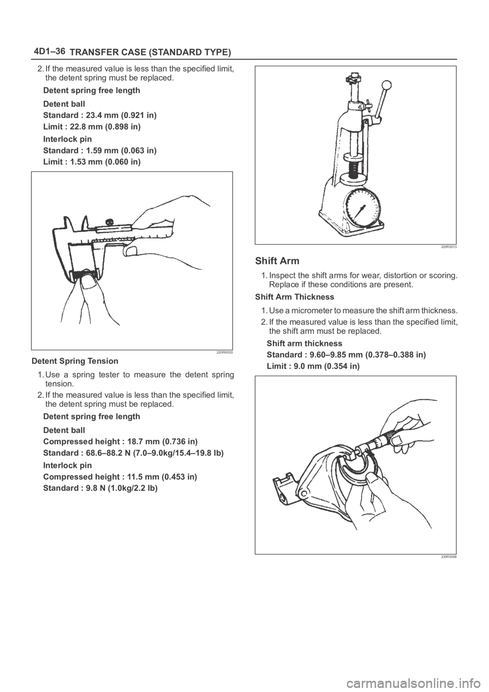
2. If the measured value is less than the specified limit,
the detent spring must be replaced.
Detent spring free length
Detent ball
Standard : 23.4 mm (0.921 in)
Limit : 22.8 mm (0.898 in)
Interlock pin
Standard : 1.59 mm (0.063 in)
Limit : 1.53 mm (0.060 in)
220RW035
Detent Spring Tension
1. Use a spring tester to measure the detent spring
tension.
2. If the measured value is less than the specified limit,
the detent spring must be replaced.
Detent spring free length
Detent ball
Compressed height : 18.7 mm (0.736 in)
Standard : 68.6–88.2 N (7.0–9.0kg/15.4–19.8 lb)
Interlock pin
Compressed height : 11.5 mm (0.453 in)
Standard : 9.8 N (1.0kg/2.2 lb)
220RS013
Shift Arm
1. Inspect the shift arms for wear, distortion or scoring.
Replace if these conditions are present.
Shift Arm Thickness
1. Use a micrometer to measure the shift arm thickness.
2. If the measured value is less than the specified limit,
the shift arm must be replaced.
Shift arm thickness
Standard : 9.60–9.85 mm (0.378–0.388 in)
Limit : 9.0 mm (0.354 in)
230RS006
Page 874 of 6000

5B–2ANTI–LOCK BRAKE SYSTEM
Electronic Hydraulic Control Unit
Electronic Hydraulic Control Unit and Associated Parts
350RW013
Legend
(1) Connector
(2) Hydraulic Unit ASM(3) Bolts
(4) Nut
(5) Bolt
Removal
1. Remove battery ASM.
2. Remove harness connector.
3. Remove EHCU fixing nuts.
4. Remove brake pipes.
After disconnecting brake pipe, cap or tape the
openings of the brake pipe to prevent the entry of
foreign matter.
5. Remove hydraulic unit fixing nuts.
Installation
To install, follow the removal steps in the reverse order,
noting the following points:
To r q u e
Hydraulic unit fixing nuts : 22 Nꞏm (2.2kgꞏm/16
lb ft)
Ground cable : 14 Nꞏm (1.4kgꞏm/10 lb ft)
Brake pipe (joint bolts) : 16 Nꞏm (1.6kgꞏm/12
lb ft)
After installing the hydraulic unit, bleed brakes
completely. Refer to Servicing in Power Assisted
Brake System section.
Page 976 of 6000
6A–20
ENGINE MECHANICAL
5. Install auto tensioner assembly and tighten the fixing
bolts to the specified torque.
Torque :
Shorter Bolt : 20 Nꞏm (2.0 Kgꞏm/14 lb ft)
Longer Bolt : 39 Nꞏm (4.0 Kgꞏm/29 lb ft)
6. Install idle pulley and bracket assembly and tighten
the fixing bolt to the specified torque.
Torque : 52 Nꞏm (5.3 Kgꞏm/38 lb ft)
7. Install fan pulley and bracket assembly and tighten
the fixing bolts and nut to the specified torque.
Torque : 22 Nꞏm (2.2 Kgꞏm/16 lb ft)
8. Install power steering oil pump pulley and tighten the
fixing bolt to the specified torque.
Torque : 78 Nꞏm (8.0 Kgꞏm/58 lb ft)
9. Install drive belt by pushing down the auto tensioner
using spanner as shown in the removal step of drive
belt.
10. Install cooling fan and clutch assembly and tighten
the fixing bolts to the specified torque.
Torque : 10 Nꞏm (1.0 Kgꞏm/87 lb in)
11. Install upper fan guide and clip both side and tighten
the fixing bolts to the specified torque.
Torque : 4 Nꞏm (0.4 Kgꞏm/35 lb in)
12. Install engine harness and tighten the fixing bolts of
the retaining clip and bracket to the specified torque.
Torque : 4 Nꞏm (0.4 Kgꞏm/35 lb in)
13. Connect radiator upper and lower hoses and clip
them securely.
14. Connect vacuum hoses of those which were
disconnected in the removal step.
15. Connect wiring connectors and bonding cable of
those which were disconnected in the removal step.
16. Install air cleaner element and air cleaner duct
assembly, and clip the both end securely.
17. Connect MAF sensor connector, IAT sensor
connector and PCV hose.
18. Install engine cover mating with the dowels.
Page 979 of 6000
6A–23
ENGINE MECHANICAL
6. Install idle pulley assembly and tighten the fixing bolt
to the specified torque.
Torque : 52 Nꞏm (5.3 Kgꞏm/38.4 lb ft)
7. Install fan pulley and bracket assembly and tighten
the fixing bolts and nut to the specified torque.
Torque : 22 Nꞏm (2.2 Kgꞏm/16.2 lb ft)
8. Install drive belt by pushing down the auto tensioner
using spanner as shown in the removal step of drive
belt.
9. Install cooling fan clutch assembly and tighten the
fixing bolts to the specified torque.
Torque : 10 Nꞏm (1.0 Kgꞏm/88.5 lb in)
10. Install upper fan guide and clip both side and tighten
the fixing bolts to the specified torque.
Torque : 4 Nꞏm (0.4 Kgꞏm/35.4 lb in)
11. Install engine harness and tighten the fixing bolts of
the retaining clip and brackets to the specified torque.
Torque : 4 Nꞏm (0.4 Kgꞏm/35.4 lb in)
12. Connect radiator upper and lower hoses and clip
them securely.
13. Connect wiring connectors and bonding cable of
those which were disconnected in the removal step.
14. Install air cleaner element and air cleaner duct
assembly, and the clip both end securely.
15. Connect MAF sensor connector, IAT sensor
connector and PCV hose.
16. Install engine cover mating with the dowels.