2.2 OPEL FRONTERA 1998 Service Manual
[x] Cancel search | Manufacturer: OPEL, Model Year: 1998, Model line: FRONTERA, Model: OPEL FRONTERA 1998Pages: 6000, PDF Size: 97 MB
Page 4026 of 6000
DIFFERENTIAL (REAR 244mm)
4A2B–19
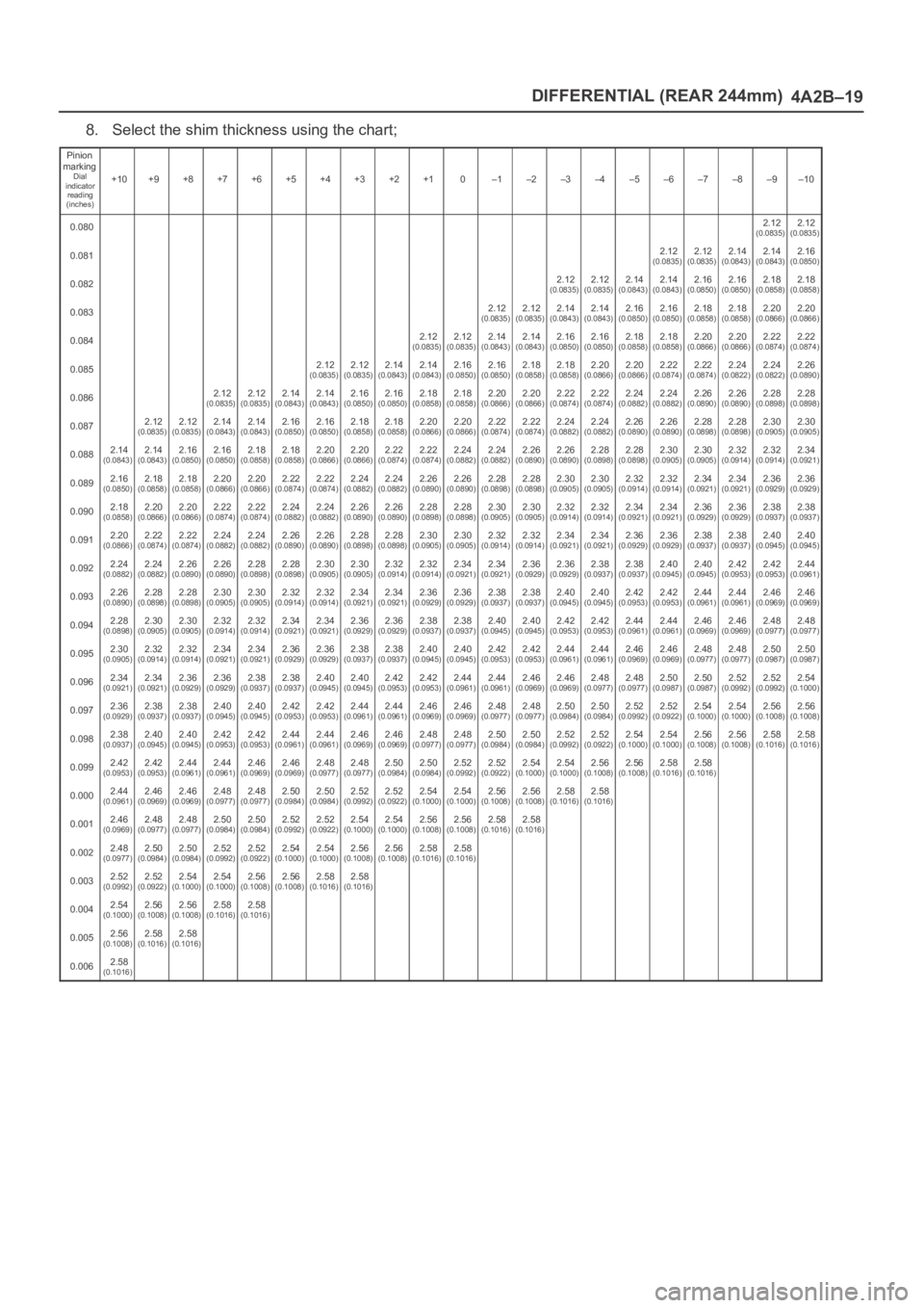
8. Select the shim thickness using the chart;
Pinion
marking
Dial
indicator
reading
(inches)+10+9+8+7+6+5+4+3+2+10–1–2–3–4–5–6–7–8–9–10
0.0802.12(0.0835)2.12(0.0835)
0.0812.12(0.0835)2.12(0.0835)2.14(0.0843)2.14(0.0843)2.16(0.0850)
0.0822.12(0.0835)2.12(0.0835)2.14(0.0843)2.14(0.0843)2.16(0.0850)2.16(0.0850)2.18(0.0858)2.18(0.0858)
0.0832.12(0.0835)2.12(0.0835)2.14(0.0843)2.14(0.0843)2.16(0.0850)2.16(0.0850)2.18(0.0858)2.18(0.0858)2.20(0.0866)2.20(0.0866)
0.0842.12(0.0835)2.12(0.0835)2.14(0.0843)2.14(0.0843)2.16(0.0850)2.16(0.0850)2.18(0.0858)2.18(0.0858)2.20(0.0866)2.20(0.0866)2.22(0.0874)2.22(0.0874)
0.0852.12(0.0835)2.12(0.0835)2.14(0.0843)2.14(0.0843)2.16(0.0850)2.16(0.0850)2.18(0.0858)2.18(0.0858)2.20(0.0866)2.20(0.0866)2.22(0.0874)2.22(0.0874)2.24(0.0822)2.24(0.0822)2.26(0.0890)
0.0862.12(0.0835)2.12(0.0835)2.14(0.0843)2.14(0.0843)2.16(0.0850)2.16(0.0850)2.18(0.0858)2.18(0.0858)2.20(0.0866)2.20(0.0866)2.22(0.0874)2.22(0.0874)2.24(0.0882)2.24(0.0882)2.26(0.0890)2.26(0.0890)2.28(0.0898)2.28(0.0898)
0.0872.12(0.0835)2.12(0.0835)2.14(0.0843)2.14(0.0843)2.16(0.0850)2.16(0.0850)2.18(0.0858)2.18(0.0858)2.20(0.0866)2.20(0.0866)2.22(0.0874)2.22(0.0874)2.24(0.0882)2.24(0.0882)2.26(0.0890)2.26(0.0890)2.28(0.0898)2.28(0.0898)2.30(0.0905)2.30(0.0905)
0.0882.14(0.0843)2.14(0.0843)2.16(0.0850)2.16(0.0850)2.18(0.0858)2.18(0.0858)2.20(0.0866)2.20(0.0866)2.22(0.0874)2.22(0.0874)2.24(0.0882)2.24(0.0882)2.26(0.0890)2.26(0.0890)2.28(0.0898)2.28(0.0898)2.30(0.0905)2.30(0.0905)2.32(0.0914)2.32(0.0914)2.34(0.0921)
0.0892.16(0.0850)2.18(0.0858)2.18(0.0858)2.20(0.0866)2.20(0.0866)2.22(0.0874)2.22(0.0874)2.24(0.0882)2.24(0.0882)2.26(0.0890)2.26(0.0890)2.28(0.0898)2.28(0.0898)2.30(0.0905)2.30(0.0905)2.32(0.0914)2.32(0.0914)2.34(0.0921)2.34(0.0921)2.36(0.0929)2.36(0.0929)
0.0902.18(0.0858)2.20(0.0866)2.20(0.0866)2.22(0.0874)2.22(0.0874)2.24(0.0882)2.24(0.0882)2.26(0.0890)2.26(0.0890)2.28(0.0898)2.28(0.0898)2.30(0.0905)2.30(0.0905)2.32(0.0914)2.32(0.0914)2.34(0.0921)2.34(0.0921)2.36(0.0929)2.36(0.0929)2.38(0.0937)2.38(0.0937)
0.0912.20(0.0866)2.22(0.0874)2.22(0.0874)2.24(0.0882)2.24(0.0882)2.26(0.0890)2.26(0.0890)2.28(0.0898)2.28(0.0898)2.30(0.0905)2.30(0.0905)2.32(0.0914)2.32(0.0914)2.34(0.0921)2.34(0.0921)2.36(0.0929)2.36(0.0929)2.38(0.0937)2.38(0.0937)2.40(0.0945)2.40(0.0945)
0.0922.24(0.0882)2.24(0.0882)2.26(0.0890)2.26(0.0890)2.28(0.0898)2.28(0.0898)2.30(0.0905)2.30(0.0905)2.32(0.0914)2.32(0.0914)2.34(0.0921)2.34(0.0921)2.36(0.0929)2.36(0.0929)2.38(0.0937)2.38(0.0937)2.40(0.0945)2.40(0.0945)2.42(0.0953)2.42(0.0953)2.44(0.0961)
0.0932.26(0.0890)2.28(0.0898)2.28(0.0898)2.30(0.0905)2.30(0.0905)2.32(0.0914)2.32(0.0914)2.34(0.0921)2.34(0.0921)2.36(0.0929)2.36(0.0929)2.38(0.0937)2.38(0.0937)2.40(0.0945)2.40(0.0945)2.42(0.0953)2.42(0.0953)2.44(0.0961)2.44(0.0961)2.46(0.0969)2.46(0.0969)
0.0942.28(0.0898)2.30(0.0905)2.30(0.0905)2.32(0.0914)2.32(0.0914)2.34(0.0921)2.34(0.0921)2.36(0.0929)2.36(0.0929)2.38(0.0937)2.38(0.0937)2.40(0.0945)2.40(0.0945)2.42(0.0953)2.42(0.0953)2.44(0.0961)2.44(0.0961)2.46(0.0969)2.46(0.0969)2.48(0.0977)2.48(0.0977)
0.0952.30(0.0905)2.32(0.0914)2.32(0.0914)2.34(0.0921)2.34(0.0921)2.36(0.0929)2.36(0.0929)2.38(0.0937)2.38(0.0937)2.40(0.0945)2.40(0.0945)2.42(0.0953)2.42(0.0953)2.44(0.0961)2.44(0.0961)2.46(0.0969)2.46(0.0969)2.48(0.0977)2.48(0.0977)2.50(0.0987)2.50(0.0987)
0.0962.34(0.0921)2.34(0.0921)2.36(0.0929)2.36(0.0929)2.38(0.0937)2.38(0.0937)2.40(0.0945)2.40(0.0945)2.42(0.0953)2.42(0.0953)2.44(0.0961)2.44(0.0961)2.46(0.0969)2.46(0.0969)2.48(0.0977)2.48(0.0977)2.50(0.0987)2.50(0.0987)2.52(0.0992)2.52(0.0992)2.54(0.1000)
0.0972.36(0.0929)2.38(0.0937)2.38(0.0937)2.40(0.0945)2.40(0.0945)2.42(0.0953)2.42(0.0953)2.44(0.0961)2.44(0.0961)2.46(0.0969)2.46(0.0969)2.48(0.0977)2.48(0.0977)2.50(0.0984)2.50(0.0984)2.52(0.0992)2.52(0.0922)2.54(0.1000)2.54(0.1000)2.56(0.1008)2.56(0.1008)
0.0982.38(0.0937)2.40(0.0945)2.40(0.0945)2.42(0.0953)2.42(0.0953)2.44(0.0961)2.44(0.0961)2.46(0.0969)2.46(0.0969)2.48(0.0977)2.48(0.0977)2.50(0.0984)2.50(0.0984)2.52(0.0992)2.52(0.0922)2.54(0.1000)2.54(0.1000)2.56(0.1008)2.56(0.1008)2.58(0.1016)2.58(0.1016)
0.0992.42(0.0953)2.42(0.0953)2.44(0.0961)2.44(0.0961)2.46(0.0969)2.46(0.0969)2.48(0.0977)2.48(0.0977)2.50(0.0984)2.50(0.0984)2.52(0.0992)2.52(0.0922)2.54(0.1000)2.54(0.1000)2.56(0.1008)2.56(0.1008)2.58(0.1016)2.58(0.1016)
0.0002.44(0.0961)2.46(0.0969)2.46(0.0969)2.48(0.0977)2.48(0.0977)2.50(0.0984)2.50(0.0984)2.52(0.0992)2.52(0.0922)2.54(0.1000)2.54(0.1000)2.56(0.1008)2.56(0.1008)2.58(0.1016)2.58(0.1016)
0.0012.46(0.0969)2.48(0.0977)2.48(0.0977)2.50(0.0984)2.50(0.0984)2.52(0.0992)2.52(0.0922)2.54(0.1000)2.54(0.1000)2.56(0.1008)2.56(0.1008)2.58(0.1016)2.58(0.1016)
0.0022.48(0.0977)2.50(0.0984)2.50(0.0984)2.52(0.0992)2.52(0.0922)2.54(0.1000)2.54(0.1000)2.56(0.1008)2.56(0.1008)2.58(0.1016)2.58(0.1016)
0.0032.52(0.0992)2.52(0.0922)2.54(0.1000)2.54(0.1000)2.56(0.1008)2.56(0.1008)2.58(0.1016)2.58(0.1016)
0.0042.54(0.1000)2.56(0.1008)2.56(0.1008)2.58(0.1016)2.58(0.1016)
0.0052.56(0.1008)2.58(0.1016)2.58(0.1016)
0.0062.58(0.1016)
Page 4297 of 6000

4D1–36
TRANSFER CASE (STANDARD TYPE)
2. If the measured value is less than the specified limit,
the detent spring must be replaced.
Detent spring free length
Detent ball
Standard : 23.4 mm (0.921 in)
Limit : 22.8 mm (0.898 in)
Interlock pin
Standard : 1.59 mm (0.063 in)
Limit : 1.53 mm (0.060 in)
220RW035
Detent Spring Tension
1. Use a spring tester to measure the detent spring
tension.
2. If the measured value is less than the specified limit,
the detent spring must be replaced.
Detent spring free length
Detent ball
Compressed height : 18.7 mm (0.736 in)
Standard : 68.6–88.2 N (7.0–9.0kg/15.4–19.8 lb)
Interlock pin
Compressed height : 11.5 mm (0.453 in)
Standard : 9.8 N (1.0kg/2.2 lb)
220RS013
Shift Arm
1. Inspect the shift arms for wear, distortion or scoring.
Replace if these conditions are present.
Shift Arm Thickness
1. Use a micrometer to measure the shift arm thickness.
2. If the measured value is less than the specified limit,
the shift arm must be replaced.
Shift arm thickness
Standard : 9.60–9.85 mm (0.378–0.388 in)
Limit : 9.0 mm (0.354 in)
230RS006
Page 4414 of 6000

5B–2ANTI–LOCK BRAKE SYSTEM
Electronic Hydraulic Control Unit
Electronic Hydraulic Control Unit and Associated Parts
350RW013
Legend
(1) Connector
(2) Hydraulic Unit ASM(3) Bolts
(4) Nut
(5) Bolt
Removal
1. Remove battery ASM.
2. Remove harness connector.
3. Remove EHCU fixing nuts.
4. Remove brake pipes.
After disconnecting brake pipe, cap or tape the
openings of the brake pipe to prevent the entry of
foreign matter.
5. Remove hydraulic unit fixing nuts.
Installation
To install, follow the removal steps in the reverse order,
noting the following points:
To r q u e
Hydraulic unit fixing nuts : 22 Nꞏm (2.2kgꞏm/16
lb ft)
Ground cable : 14 Nꞏm (1.4kgꞏm/10 lb ft)
Brake pipe (joint bolts) : 16 Nꞏm (1.6kgꞏm/12
lb ft)
After installing the hydraulic unit, bleed brakes
completely. Refer to Servicing in Power Assisted
Brake System section.
Page 4516 of 6000
6A–20
ENGINE MECHANICAL
5. Install auto tensioner assembly and tighten the fixing
bolts to the specified torque.
Torque :
Shorter Bolt : 20 Nꞏm (2.0 Kgꞏm/14 lb ft)
Longer Bolt : 39 Nꞏm (4.0 Kgꞏm/29 lb ft)
6. Install idle pulley and bracket assembly and tighten
the fixing bolt to the specified torque.
Torque : 52 Nꞏm (5.3 Kgꞏm/38 lb ft)
7. Install fan pulley and bracket assembly and tighten
the fixing bolts and nut to the specified torque.
Torque : 22 Nꞏm (2.2 Kgꞏm/16 lb ft)
8. Install power steering oil pump pulley and tighten the
fixing bolt to the specified torque.
Torque : 78 Nꞏm (8.0 Kgꞏm/58 lb ft)
9. Install drive belt by pushing down the auto tensioner
using spanner as shown in the removal step of drive
belt.
10. Install cooling fan and clutch assembly and tighten
the fixing bolts to the specified torque.
Torque : 10 Nꞏm (1.0 Kgꞏm/87 lb in)
11. Install upper fan guide and clip both side and tighten
the fixing bolts to the specified torque.
Torque : 4 Nꞏm (0.4 Kgꞏm/35 lb in)
12. Install engine harness and tighten the fixing bolts of
the retaining clip and bracket to the specified torque.
Torque : 4 Nꞏm (0.4 Kgꞏm/35 lb in)
13. Connect radiator upper and lower hoses and clip
them securely.
14. Connect vacuum hoses of those which were
disconnected in the removal step.
15. Connect wiring connectors and bonding cable of
those which were disconnected in the removal step.
16. Install air cleaner element and air cleaner duct
assembly, and clip the both end securely.
17. Connect MAF sensor connector, IAT sensor
connector and PCV hose.
18. Install engine cover mating with the dowels.
Page 4519 of 6000
6A–23
ENGINE MECHANICAL
6. Install idle pulley assembly and tighten the fixing bolt
to the specified torque.
Torque : 52 Nꞏm (5.3 Kgꞏm/38.4 lb ft)
7. Install fan pulley and bracket assembly and tighten
the fixing bolts and nut to the specified torque.
Torque : 22 Nꞏm (2.2 Kgꞏm/16.2 lb ft)
8. Install drive belt by pushing down the auto tensioner
using spanner as shown in the removal step of drive
belt.
9. Install cooling fan clutch assembly and tighten the
fixing bolts to the specified torque.
Torque : 10 Nꞏm (1.0 Kgꞏm/88.5 lb in)
10. Install upper fan guide and clip both side and tighten
the fixing bolts to the specified torque.
Torque : 4 Nꞏm (0.4 Kgꞏm/35.4 lb in)
11. Install engine harness and tighten the fixing bolts of
the retaining clip and brackets to the specified torque.
Torque : 4 Nꞏm (0.4 Kgꞏm/35.4 lb in)
12. Connect radiator upper and lower hoses and clip
them securely.
13. Connect wiring connectors and bonding cable of
those which were disconnected in the removal step.
14. Install air cleaner element and air cleaner duct
assembly, and the clip both end securely.
15. Connect MAF sensor connector, IAT sensor
connector and PCV hose.
16. Install engine cover mating with the dowels.
Page 4524 of 6000
6A–28
ENGINE MECHANICAL
Crankshaft Pulley
Removal
1. Disconnect battery ground cable.
2. Remove air cleaner assembly.
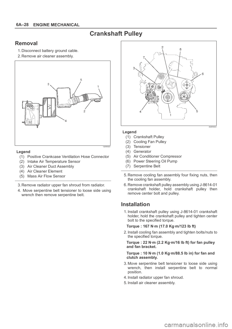
130RW001
Legend
(1) Positive Crankcase Ventilation Hose Connector
(2) Intake Air Temperature Sensor
(3) Air Cleaner Duct Assembly
(4) Air Cleaner Element
(5) Mass Air Flow Sensor
3. Remove radiator upper fan shroud from radiator.
4. Move serpentine belt tensioner to loose side using
wrench then remove serpentine belt.
850RW001
Legend
(1) Crankshaft Pulley
(2) Cooling Fan Pulley
(3) Tensioner
(4) Generator
(5) Air Conditioner Compressor
(6) Power Steering Oil Pump
(7) Serpentine Belt
5. Remove cooling fan assembly four fixing nuts, then
the cooling fan assembly.
6. Remove crankshaft pulley assembly using J-8614-01
crankshaft holder, hold crankshaft pulley then
remove center bolt and pulley.
Installation
1. Install crankshaft pulley using J-8614-01 crankshaft
holder, hold the crankshaft pulley and tighten center
bolt to the specified torque.
Torque : 167 Nꞏm (17.0 Kgꞏm/123 lb ft)
2. Install cooling fan assembly and tighten bolts/nuts to
the specified torque.
Torque : 22 Nꞏm (2.2 Kgꞏm/16 lb ft) for fan pulley
and fan bracket.
Torque : 10 Nꞏm (1.0 Kgꞏm/88.5 lb in) for fan and
clutch assembly.
3. Move serpentine belt tensioner to loose side using
wrench, then install serpentine belt to normal
position.
4. Install radiator upper fan shroud.
5. Install air cleaner assembly.
Page 4528 of 6000

6A–32
ENGINE MECHANICAL
Legend
(1) Up Side
(2) Down Side
(3) Direction for Installation
(4) Locking Pin
3. Remove double clips or equivalent clips, from
timing belt pulleys.
Turn the crankshaft pulley clockwise by two turns.
3. Install timing belt cover.
Remove crankshaft pulley that was installed in step
1 item 5.
Tighten bolts to the specified torque.
Torque: 19 Nꞏm (1.9 Kgꞏm/14 lb ft)
020RW004
Legend
(1) Timing Belt Cover RH
(2) Timing Belt Cover LH
(3) Timing Belt Cover Lower
020RW003
Legend
(1) Timing Belt Cover
(2) Rubber Bushing
(3) Sealing Rubber
(4) Cylinder Body
4. Install crankshaft pulley using 5–8840–0133–0, hold
the crankshaft pulley and tighten center bolt to the
specified torque.
Torque : 167 Nꞏm (17.0 Kgꞏm/123 lb ft)
5. Install fan pulley bracket and tighten fixing bolts to the
specified torque.
Torque : 22 Nꞏm (2.2 Kgꞏm/16 lb ft)
6. Install power steering pump assembly and tighten to
the specified torque.
To r q u e :
M8 bolt : 22 Nꞏm (2.2 Kgꞏm/16 lb ft)
M10 bolt : 46 Nꞏm (4.7 Kgꞏm/34 lb ft)
7. Install cooling fan assembly and tighten bolts/nuts to
the specified torque.
Torque : 22 Nꞏm (2.2 Kgꞏm/16 lb ft) for fan pulley
and fan bracket.
Torque : 10 Nꞏm (1.0 Kgꞏm/88.5 lb in) for fan and
clutch assembly.
8. Move drive belt tensioner to loose side using wrench,
then install drive belt to normal position.
850RW001
Legend
(1) Crankshaft Pulley
(2) Cooling Fan Pulley
(3) Auto Tensioner
(4) Generator
(5) Air Conditioner Compressor
(6) Power Steering Oil Pump
(7) Idle Pulley
(8) Drive Belt
9. Install radiator upper fan shroud.
10. Install air cleaner assembly.
Page 4545 of 6000

6A–49
ENGINE MECHANICAL
If the engine is assembled in the condition that the
dowels have not been mounted in the specified posi-
tions, the transmission may be damaged the trans-
mission.
012RS009
1. Install engine assembly. Tighten engine mount fixing
bolts to frame to the specified torque.
Torque: 41 Nꞏm (4.2 Kgꞏm/30 lb ft)
2. Reconnect fuel hose to fuel pipe on engine.
3. Install transmission assembly. Refer to Transmission
section in this manual.
4. Reconnect two heater hoses to engine.
5. Install flywheel dust covers.
6. Install exhaust pipe and temporally tighten two (each
bank) rear exhaust flange nuts then tighten three stud
nuts (each bank) between exhaust manifold and
exhaust pipe, finally tighten rear side nuts to the
specified torque.
Torque:
Nuts: 43 Nꞏm (4.4 Kgꞏm/32 lb ft)
Stud nuts: 67 Nꞏm (6.8 Kgꞏm/49 lb ft)
150RW061
Legend
(1) Exhaust Front Pipe RH
(2) O
2 Sensor (for IGM)
150RW062
Legend
(1) Exhaust Front Pipe LH
7. Reconnect O2 sensor connector.
8. Install cooling fan assembly and tighten bolts/nuts to
the specified torque.
Torque : 22 Nꞏm (2.2 Kgꞏm/16 lb ft) for fan pulley
and fan bracket.
Torque : 10 Nꞏm (1.0 Kgꞏm/88.5 lb in) for fan and
clutch assembly.
Page 4546 of 6000
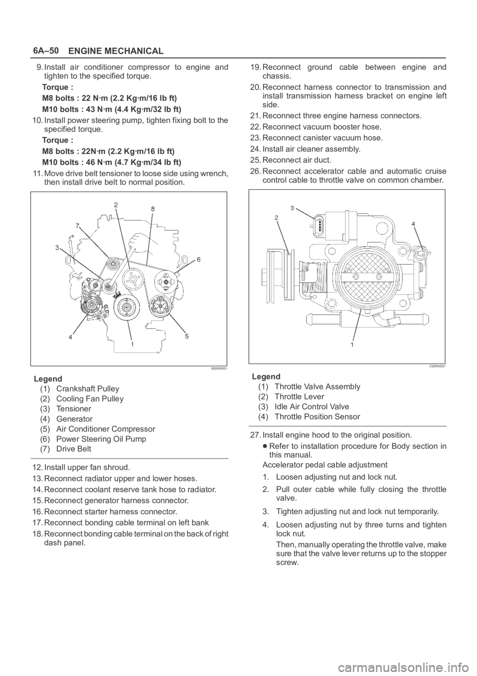
6A–50
ENGINE MECHANICAL
9. Install air conditioner compressor to engine and
tighten to the specified torque.
Torque :
M8 bolts : 22 Nꞏm (2.2 Kgꞏm/16 lb ft)
M10 bolts : 43 Nꞏm (4.4 Kgꞏm/32 lb ft)
10. Install power steering pump, tighten fixing bolt to the
specified torque.
Torque :
M8 bolts : 22Nꞏm (2.2 Kgꞏm/16 lb ft)
M10 bolts : 46 Nꞏm (4.7 Kgꞏm/34 lb ft)
11. Move drive belt tensioner to loose side using wrench,
then install drive belt to normal position.
850RW001
Legend
(1) Crankshaft Pulley
(2) Cooling Fan Pulley
(3) Tensioner
(4) Generator
(5) Air Conditioner Compressor
(6) Power Steering Oil Pump
(7) Drive Belt
12. Install upper fan shroud.
13. Reconnect radiator upper and lower hoses.
14. Reconnect coolant reserve tank hose to radiator.
15. Reconnect generator harness connector.
16. Reconnect starter harness connector.
17. Reconnect bonding cable terminal on left bank
18. Reconnect bonding cable terminal on the back of right
dash panel.19. Reconnect ground cable between engine and
chassis.
20. Reconnect harness connector to transmission and
install transmission harness bracket on engine left
side.
21. Reconnect three engine harness connectors.
22. Reconnect vacuum booster hose.
23. Reconnect canister vacuum hose.
24. Install air cleaner assembly.
25. Reconnect air duct.
26. Reconnect accelerator cable and automatic cruise
control cable to throttle valve on common chamber.
035RW007
Legend
(1) Throttle Valve Assembly
(2) Throttle Lever
(3) Idle Air Control Valve
(4) Throttle Position Sensor
27. Install engine hood to the original position.
Refer to installation procedure for Body section in
this manual.
Accelerator pedal cable adjustment
1. Loosen adjusting nut and lock nut.
2. Pull outer cable while fully closing the throttle
valve.
3. Tighten adjusting nut and lock nut temporarily.
4. Loosen adjusting nut by three turns and tighten
lock nut.
Then, manually operating the throttle valve, make
s u r e t h a t t h e v a l v e l e v e r r e t u r n s u p t o t h e s t o p p e r
screw.
Page 4578 of 6000

6A–82
ENGINE MECHANICAL
4. Reinstall the rod caps (12) to their original
positions.
Tighten the rod cap nuts.
Torque: 54 Nꞏm (5.5 Kgꞏm/40 lb ft)
NOTE: Do not allow the crankshaft to rotate.
5. Remove the rod caps.
6. Measure the width of the plastigage and
determine the oil clearance. If the oil clearance
exceeds the limit, replace the rod bearing as a
set.
Standard : 0.019 mm–0.043 mm
(0.0007 in–0.0017 in)
Limit : 0.08 mm (0.003 in)
015RS008
7. Clean the plastigage from the bearings and the
crankshaft pins.
Con–rod Bearing Selection
Select and install the new connecting rod bearings,
paying close attention to the connecting rod big end
diameter size mark (1).
NOTE: Take care not to confuse the alignment mark (2)
and the size mark (1) during the installation procedure.
015RS034
1 Size MarkBig end Bore
DiameterCrankshaft Pin
DiameterConnecting Rod
Bearing Thickness
(Reference)Color of
Size
MarkOil Clearance
(Reference)
A56.994-57.000
(2.2439-2.2441)1.512-1.516
(0.0595-0.0597)Ye l l o w0.025-0.054
(0.0010-0.0021)
B56.988-56.994
(2.2436-2.2439)53.922-53.937
(2.1229-2.1235)1.508-1.512
(0.0594-0.0595)Green0.027-0.056
(0.0011-0.0022)
C56.982-56.988
(2.2434-2.2436)1.504-1.508
(0.0592-0.0594)Pink0.029-0.058
(0.0011-0.0023)
Reassembly
1. Install connecting rod
2. Install piston3. Install piston pinApply a thin coat of engine oil to the piston pin. Try to
insert the piston pin into the piston pin hole with
normal finger pressure.
NOTE: When changing piston / connecting rod
combinations, do not change the piston / piston pin
combination and do not reuse the old piston pin.