2.2 OPEL FRONTERA 1998 Owner's Manual
[x] Cancel search | Manufacturer: OPEL, Model Year: 1998, Model line: FRONTERA, Model: OPEL FRONTERA 1998Pages: 6000, PDF Size: 97 MB
Page 1749 of 6000

6A – 16 ENGINE MECHANICAL
Intake / Exhaust Manifold
Nꞏm (kgꞏm/lbꞏft)
025R200003
For Europe
For Europe 20(2.0/14.5)
20(2.0/14.5)
20(2.0/14.5)
22(2.2/16)
22(2.2/16)
30(3.1/22)
30(3.1/22)
20(2.0/14.5)
Page 1754 of 6000

ENGINE MECHANICAL 6A – 21
Air Duct and Intercooler (For General Export)
Nꞏm (kgꞏm/lbꞏft)
3.0(0.3/2.2)
4.0(0.4/3)
20(2.0/14.5)
4.0(0.4/3)
20(2.0/14.5)
135R200002
Page 1755 of 6000

6A – 22 ENGINE MECHANICAL
Air Duct and Intercooler (For Europe)
Nꞏm (kgꞏm/lbꞏft)
4.0(0.4/3)
4.0(0.4/3)
3.0(0.3/2.2) 20(2.0/14.5)
135R200001
Page 1773 of 6000

6A – 40 ENGINE MECHANICAL
INSTALLATION
1. Install turbocharger assembly to exhaust manifold,
tighten to the specified torque.
Torque : 27 Nꞏm (2.8 kgꞏm/20.2 lb ft)
2. Install exhaust adaptor.
Torque : 27 Nꞏm (2.8 kgꞏm/20.2 lb ft)
3. Install heat protector.
4. Install water outlet pipe with gasket.
Torque : 9 Nꞏm (0.9 kgꞏm/6.5 lb ft)
5. Install turbocharger oil drain pipe.
Torque : 9 Nꞏm (0.9 kgꞏm/6.5 lb ft)6. Install oil supply pipe to turbocharger.
1) Fill with 100 cc engine oil at the turbocharger oil
supply hole before installing the oil pipe.
2) Turn the turbocharger by hand to lubricate
turbocharger shaft.
3) Install oil supply pipe with new gasket to the
turbocharger and tighten oil supply pipe bolts to
the specified torque.
Torque : 22 Nꞏm (2.2 kgꞏm/15.9 lb ft) for M10
54 Nꞏm (5.5 kgꞏm/39.8 lb ft) for M14
7. Install water inlet pipe with new gasket, tighten to
the specified torque.
Torque : 9 Nꞏm (0.9 kgꞏm/6.5 lb ft)
8. Install intercooler assembly.
Refer to “Intercooler” in this manual.
9. Install air cleaner cover with air duct, connect both
side hoses.
10. Fill with engine coolant.
11. Install the battery and connect battery cables.
For Europe
025R200007
For Europe
025R200007
For Europe
025R200006
Page 1781 of 6000

6A – 48 ENGINE MECHANICAL
DISASSEMBLY
1. Injector clamp
2. Injector assembly
3. Oil rail assembly
4. Camshaft bracket
5. Camshaft
6. Oil seal
7. Plug
NOTE: Before starting disassembly above, drain oil
from oil rail to prevent oil from entering the cylinder.
REASSEMBLY
1. Camshaft
1) Before reassembling the camshaft to the
camshaft carrier, align the holes between the
main gear and the sub gear on the intake side of
the camshaft gear with a special tool.
2) Set lock pin to gear holes from sub gear side.
Camshaft Gear Tool: 5-8840-2591-0
Legend
(1) Locking pin
(2) Special tool
3) Apply engine oil to the camshaft gear tooth.
4) Apply engine oil to the journal on the camshaft
carrier.
5) Align the timing mark on the intake and exhaust
camshaft gear and put on the camshaft carrier.Legend
(1) Locking pin
(2) Intake side camshaft gear
(3) Exhaust side camshaft gear
6) Apply liquid gasket (TB1207B or equivalent) to
No. 1 camshaft bracket matching surface.
7) Set No. 1 to No. 5 camshaft bracket on camshaft
carrier.
8) Temporarily tighten bracket bolts B and C.
Temporal Torque: 20 Nꞏm (2.0 kgꞏm/14.5 lb ft)
9) Put gasket on the cylinder head.
10) Install camshaft carrier onto the cylinder head
and tighten bolts to specified torque.
Torque: A; 22 Nꞏm (2.2 kgꞏm/15.9 lb ft)
B; 38 Nꞏm (3.9 kgꞏm/28.2 lb ft)
C; 22 Nꞏm (2.2 kgꞏm/15.9 lb ft)
D; 38 Nꞏm (3.9 kgꞏm/28.2 lb ft)
Remove locking pin.
1
2
014RW183
321
014RW184
CC
D
B
CC
B
CC
D
CC
B
C
A AA A A A
AAAA
011RW035
Page 1782 of 6000
ENGINE MECHANICAL 6A – 49
INSPECTION AND REPAIR
Make the necessary adjustments, repairs, and part
replacements if excessive wear or damage is
discovered during inspection.
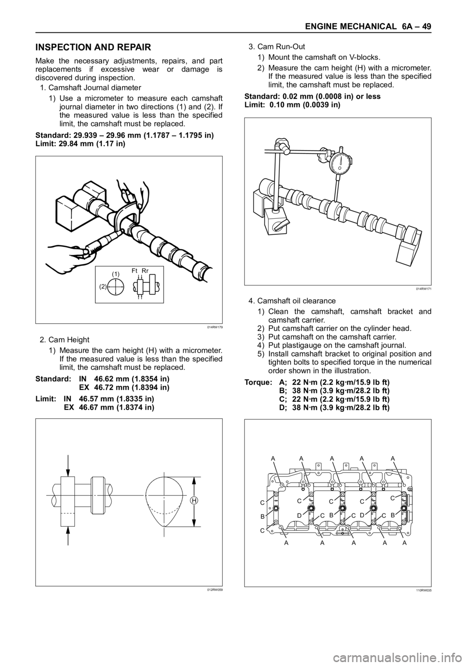
1. Camshaft Journal diameter
1) Use a micrometer to measure each camshaft
journal diameter in two directions (1) and (2). If
the measured value is less than the specified
limit, the camshaft must be replaced.
Standard: 29.939 – 29.96 mm (1.1787 – 1.1795 in)
Limit: 29.84 mm (1.17 in)
2. Cam Height
1) Measure the cam height (H) with a micrometer.
If the measured value is less than the specified
limit, the camshaft must be replaced.
Standard: IN 46.62 mm (1.8354 in)
EX 46.72 mm (1.8394 in)
Limit: IN 46.57 mm (1.8335 in)
EX 46.67 mm (1.8374 in)3. Cam Run-Out
1) Mount the camshaft on V-blocks.
2) Measure the cam height (H) with a micrometer.
If the measured value is less than the specified
limit, the camshaft must be replaced.
Standard: 0.02 mm (0.0008 in) or less
Limit: 0.10 mm (0.0039 in)
4. Camshaft oil clearance
1) Clean the camshaft, camshaft bracket and
camshaft carrier.
2) Put camshaft carrier on the cylinder head.
3) Put camshaft on the camshaft carrier.
4) Put plastigauge on the camshaft journal.
5) Install camshaft bracket to original position and
tighten bolts to specified torque in the numerical
order shown in the illustration.
Torque: A; 22 Nꞏm (2.2 kgꞏm/15.9 lb ft)
B; 38 Nꞏm (3.9 kgꞏm/28.2 lb ft)
C; 22 Nꞏm (2.2 kgꞏm/15.9 lb ft)
D; 38 Nꞏm (3.9 kgꞏm/28.2 lb ft)
(1)Ft Rr
(2)
014RW179
H
012RW059
014RW171
CC
D
B
CC
B
CC
D
CC
B
C
A AA A A A
AAAA
110RW035
Page 1783 of 6000

6A – 50 ENGINE MECHANICAL
NOTE: Do not allow the camshaft to rotate.
6) Remove the camshaft bracket and measure the
plastigauge width and determine the oil
clearance. If the oil clearance exceeds the
specified limit, replace the camshaft carrier
and/or camshaft.
Oil clearance.
Standard: 0.040 – 0.082 mm (0.0016 – 0.0032 in)
Limit: 0.12 mm (0.0047 in)
7) Clean the plastigauge from the camshaft bracket
and camshaft carrier.
5. Camshaft thrust clearance.
1) Clean the camshaft, camshaft bracket and
camshaft carrier.
2) Put camshaft carrier on the cylinder head.
3) Put camshaft on the camshaft carrier.
4) Put plastigauge on the camshaft journal.5) Install camshaft bracket to original position and
tighten bolts to specified torque in the numerical
order shown in the illustration.
Torque: A; 22 Nꞏm (2.2 kgꞏm/15.9 lb ft)
B; 38 Nꞏm (3.9 kgꞏm/28.2 lb ft)
C; 22 Nꞏm (2.2 kgꞏm/15.9 lb ft)
D; 38 Nꞏm (3.9 kgꞏm/28.2 lb ft)
6) Use a dial indicator to measure the camshaft
thrust clearance. If the camshaft thrust
clearance exceeds the specified limit, replace
the camshaft carrier and/or camshaft.
Camshaft thrust clearance
Standard: 0.1 mm (0.0002 in)
Limit: 0.2 mm (0.0078 in)
13
7
6
5
1215
2
3
10
9
20
8
19
2322
4
161
11 25
24
21
17
18
011RW041
014RW185
CC
D
B
CC
B
CC
D
CC
B
C
A AA A A A
AAAA
011RW035
13
7
6
5
1215
2
3
10
9
20
8
19
2322
4
161
11 25
24
21
17
18
011RW041
Page 1830 of 6000

ENGINE MECHANICAL 6A – 97
11. Use the special tool to install the crankshaft front oil
seal to timing gear case.
Front Oil Seal Installer: 5-8840-2061-0
1) Check fit-of the oil seal and gear case cover at
the front end.
Standard: 0.5 – 2.5 mm (0.0197 – 0.0984 in)
NOTE: Apply engine oil to oil seal lip before installation
of the seal.
12. Install the oil pan assembly to original position and
tighten to specified torque.
Torque: 22 Nꞏm (2.2 kgꞏm/15.9 lb ft)
13. Crankshaft Rear Oil Seal
1) Tighten the adapter to the crankshaft rear end
with 2 bolts.
2) Insert the oil seal into the adapter.
3) Insert the sleeve into the adapter and tighten it
with a bolt (M12 x 1.75L = 70) until the adapter
hits the sleeve.
4) Remove the adapter and the sleeve.
5) With the seal pressed in, check the dimension of
the oil seal outside end and crankshaft end.
Standard Dimension = 12.5 ± 0.3 mm
Oil Seal Installer: 5-8840-2359-014. Cylinder Block Rear Plate (A/T Model)
1) Tighten the cylinder block rear plate fixing bolts
to the specified torque.
Torque: 97 Nꞏm (9.9 kgꞏm/72 lb ft)
15. Flywheel Housing (M/T Model)
1) Install flywheel housing aligned with the dowel
pin on the cylinder block.
2) Tighten the flywheel housing fixing bolts to the
specified torque.
Torque: 97 Nꞏm (9.9 kgꞏm/72 lb ft)
16. Flywheel
1) Refer to “Crankshaft” in this manual.
17. Cylinder Head Assembly
1) Refer to “Cylinder Head” in this manual.
015RW074
12.5 + 0.3–
012RW067
Page 2148 of 6000

INDUCTION 6J – 7
Legend
(1) Pressure gauge
(2) Waste gate control rod
4) Check for cracks or breaks on the hose, if a
problem is found, the hose must be replaced.
CAUTION: Do not apply more than 120 Kpa (900
mmHg / 18.7 PSi) to waste gate actuator.
INSTALLATION
1. Install turbocharger assembly to exhaust manifold,
tighten to the specified torque.
Torque: 27 Nꞏm (2.7 kgꞏm / 19.5 lb ft)2. Install exhaust valve assembly to outlet of
turbocharger, tighten bolts to the specified torque.
Torque: 27 Nꞏm (2.7 kgꞏm / 19.5 lb ft)
3. Install heat protector.
4. Water inlet pipe.
1) Tighten water inlet pipe with new gasket.
Torque: 9 Nꞏm (0.9 kgꞏm / 6.5 lb ft)
5. Oil drain pipe.
1) Tighten oil drain pipe with new gasket.
Torque: 9 Nꞏm (0.9 kgꞏm / 6.5 lb ft)
6. Oil inlet pipe.
1) Apply about 100 cc engine oil to turbocharger
housing before installing the oil pipe.
2) Turn the turbine shaft by hand to lubricate the
bearing.
3) Install the oil inlet pipe with a new gasket, tighten
bolt to the specified torque.
Torque: 22 Nꞏm (2.2 kgꞏm / 15.9 lb ft) For M10
Torque: 54 Nꞏm (5.5 kgꞏm / 39.8 lb ft) For M14
2
1
036RW011
For Europe
025R200007
For Europe
025R200006
Page 2201 of 6000

7A–47 AUTOMATIC TRANSMISSION (4L30–E)
36. Separate second (40) and third clutch (41)
assemblies.
37. Remove thrust washer (42).
38. Remove reverse clutch plates (43 and 44) and
reverse clutch pressure plate (45).
39. Remove bearing (46) and washer (47).
40. Remove planetary carrier assembly (48).
41. Remove thrust bearing (49).
42. Remove reaction sun gear (50)
43. Remove needle bearing (51).
44. Remove brake drum (52).
45. Remove brake band (53).
46. Remove thrust bearing (54).
242RS003
47. Rotate case to horizontal position, valve body side
facing up.
Remove spring pin (55), using cutting pliers, then
remove parking lock and selector lever assembly
(56).NOTE: Insert wire in the center of the spring pin to
prevent it from collapsing during removal. Be aware of pin
height. Protect machined face of main case.
48. Remove parking lock and range selector lever 17 mm
nut (57).
49. Remove parking lock and range selector lever (56),
and actuator assembly.
50. Remove selector shaft (58).
NOTE: Inspect the shaft for burrs before removing to
prevent damaging seal. If necessary, remove burrs by
lightly sanding with an oilstone.
249RS004
Reassembly
1. Inspect selector shaft seal, and replace it if
necessary.
NOTE: Use a seal installer when replacing the seal.
Install selector shaft.
NOTE: Spring pin groove must be positioned inside the
case.
2. Install spring pin. Be sure the selector shaft can move
freely. Do not push the pin flush with the case surface.
Leave enough height for removal.
3. Install actuator assembly (1).
4. Install parking lock and range selector lever (2) and
new 17 mm nut. Tighten the nut to the specified
torque.
To r q u e : 2 2 N
m (2.2 kgꞏm/16 lb ft)