air condition OPEL FRONTERA 1998 Workshop Manual
[x] Cancel search | Manufacturer: OPEL, Model Year: 1998, Model line: FRONTERA, Model: OPEL FRONTERA 1998Pages: 6000, PDF Size: 97 MB
Page 4 of 6000

PAGE BACK PAGE NEXT
THIS MALUAL INCLUDES THE FOLLOWING SECTIONS:
SECTION No. CONTRNTS
00 SERVICE INFORMATION
1A HEATING AND VENTILATION
1B AIR CONDITIONING
1D COMPRESSOR OVERHAUL
HOME
00
1D
1B
1A
Page 201 of 6000

FULL AUTO display
INTAKE indication
(LED)
(switching between
fresh and interior air)
MODE indication
(LED) (Blow port)
AC display (LED)
FAN indication (LED)
FAN KNOB
AUTO SET
REC FRESH SWITCH
TEMP LEVER
(temperature control)
MODE SWITCH
(blow port selection)
AC SWITCH
IN CAR SENSOR
AMBIENT SENSOR
SUN SENSOR
DUCT SENSOR
MIX ACTUATOR
POTENTIOMETER
MODE ACTUATOR
POTENTIOMETER
AIR MIX DOOR
MODE DOOR
INTAKE ACTUATOR
RECINTAKE DOOR
FAN MOTORPOWER
TRANSISTOR
AUTOMATIC HEATER/AIR CONDITIONER CONTROL UNIT (with the built-in micro-computer)
MAX HI RELAY
PRESSURE
SWITCHAIR CONDITIONER
THERMO RELAY
COMPRESSOR
SWITCH MAGNET
CLUTCH
PCM
PRESSURE
SWITCHAIR CONDITIONER
THERMO RELAYMAGNET
CLUTCH
(4JX1engine)
MIX FRESH
F01RY00009
Page 212 of 6000

12
43
860RW026
C01RX016
M
N 3
2
7
6
8
98 43
65 21
7
Potentiometer
ConnectionPosition
Detection
Block Automatic Heater / Air
Conditioner Control Unit
Controller
Sliding Contact
Full Heate PositionTerminal PlateFull Cool PositionDriver
Cool Side Heat Side
C01RX005
Full cool
Full cool0 0 0.5 1.0
50 100%
Aperture of air mix doorVoltage ratio VM/VDD
Full heat Full heat
VDD
VM +
–
Page 214 of 6000

0 50
140 104 68 32
Air mix door aperture
Full cool
Heater
side Restriction on the
aperture enabied
in the VENT modeAir conditioning
ON mode Full heatSet temperature
signal
Mix
actuator
Potentio
meter
Air mix door
In car sensor
Ambient sensor
Sun sensor
Control unitAir conditioning
switch
Set up temperature
signal
Air conditioning
OFF mode
Total signal Cooler
side
C01RY00011
Page 215 of 6000

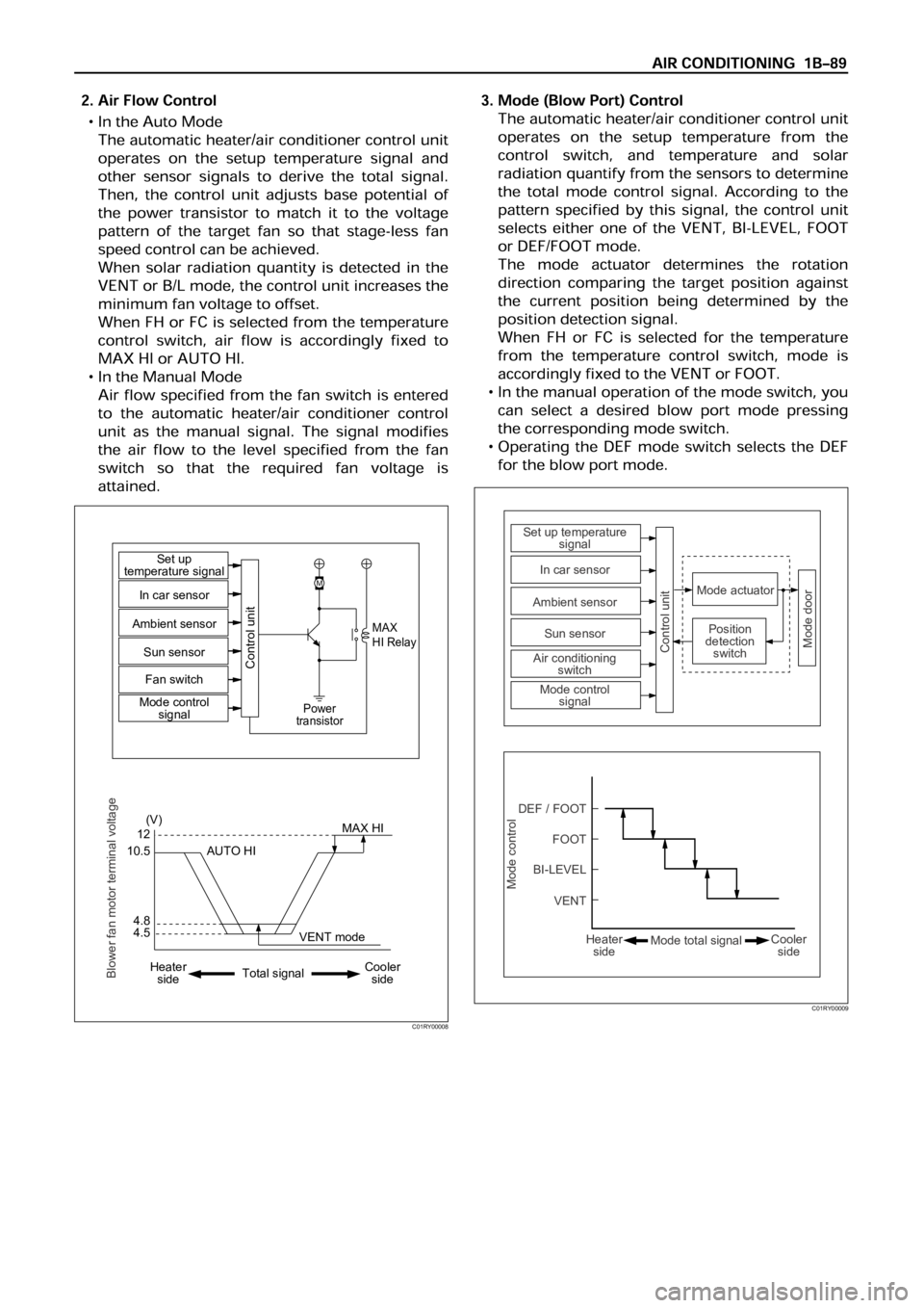
4.512
(V)
M
MAX
HI Relay
Power
transistor
4.8 10.5MAX HI Set up
temperature signal
Control unit
In car sensor
Ambient sensor
Sun sensor
Mode control
signal Fan switch
AUTO HI
Heater
sideCooler
side Total signalVENT mode
Blower fan motor terminal voltage
C01RY00008
Mode control
DEF / FOOTSet up temperature
signal
Mode actuator
Mode doorPosition
detection
switch
Control unit
In car sensor
Sun sensor
Air conditioning
switch
Mode control
signal Ambient sensor
FOOT
BI-LEVEL
VENT
Heater
sideCooler
side Mode total signal
C01RY00009
Page 216 of 6000

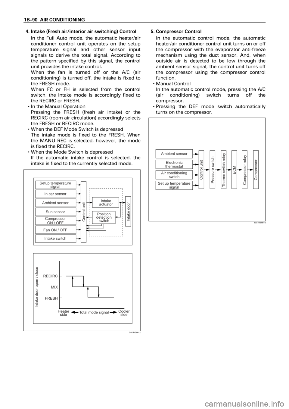
Intake door open / close
RECIRC Setup temperature
signal
Intake
actuator
Position
detection
switch
In car sensor
Ambient sensor
Sun sensor
Compressor
ON / OFF
Fan ON / OFF
Intake switch
Control unit
Intake door
MIX
FRESH
Heater
sideCooler
side Total mode signal
C01RY00012
Ambient sensor
Control unit
Pressure switch
Thermo switch relay
ECM
Compressor relay
Compressor
Electronic
thermostat
Air conditioning
switch
Set up temperature
signal
C01RY00010
Page 218 of 6000

Occurrence of a trouble
Refer to the check list for
the inspection.Locate the failed location.
Check the failed part.
Correction
Correction
Correction
Troubleshooting by the
self-diagnosis function.Reference the "Check
Procedure by Failed
Location" for the inspection.
Reference the "Check
Procedure by Failed
Location" for the inspection.Correction
Check the cooling / heating
cycles.
End OK OK OK OKNG
NG
NG
NG
NG OK
Check if the automatic
heater / air conditioner
control unit indicator LED
is turned on.Check the power supply and
circuit on the automatic
heater / air conditioner control
unit.
Troubleshooting not relying
on the self-diagnosis
function(troubleshooting
by failure type).
F01RX009
Page 219 of 6000

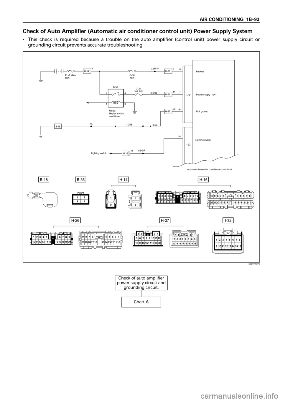
B-18
FL-1 Main
80A
0.5G/R16
107 8
I-32
I-32 C-16
10A0.3R/W
0.5BRBackup
Power supply (12V)
Unit ground
Automatic heater/air conditioner control unit
B-18B-36H-14
C-20
10A A/C
Relay:
Heater and air
conditioner
0.5B
1.25B 2B
Lighting switchLighting switch
H-141H-269
H-2614
H-2720
H-1614 2
14
3 B-36
H-16
H-26H-27I-32
D08RY00175
Page 247 of 6000

C-25
0.5 BR
C-25
X-5X-5
X-5X-5
2 1
4 3
0.5 P/G FL-1 MAIN
80A
C-20
10A A/C
0.5 G/W 0.5 G/O
C-25E-27H-16
Pressure
switch
Relay:
Air conditioning
thermostat
Automatic heater/air conditioner
control unitRelay:
Air conditioning
0.5 BR
1
2
I-3214
Fan “ON”
I-32X-5
E-271
Magnet
clutch
B-36
B-36
H-1616
D08RY00183
Page 281 of 6000

1. Perform oil return operation.
2. Discharge and recover the refrigerant and remove
the compressor.
3. Drain the compressor oil and measure the extracted
oil.
4. Check the compressor oil for contamination.
5. Adjust the oil level as required.
6. Evacuate, charge and perform the oil return
operation.
7. Check the system operation.
Contamination of Compressor Oil
Unlike engine oil, no cleaning agent is added to the
compressor oil. Even if the compressor runs for a long
period of time (approximately one season), the oil never
becomes contaminated as long as there is nothing
wrong with the compressor or its method of use.
Inspect the extracted oil for any of the following
conditions:
The capacity of the oil has increased.
The oil has changed to red.
Foreign substances, metal powder, etc., are present
in the oil.
If any of these conditions exists, the compressor
oil is contaminated. Whenever contaminated
compressor oil is discovered, the receiver/drier
must be replaced.
Oil Return Operation
There is close affinity between the oil and the
refrigerant. During normal operation, part of the oil
recirculates with the refrigerant in the system. When
checking the amount of oil in the system, or replacing
any component of the system, the compressor must be
run in advance for oil return operation. The procedure
is as follows:
1. Open all the doors and the engine hood.
2. Start the engine and air conditioning switch to "ON"
and set the fan control knob at its highest position.
3. Run the compressor for more than 20 minutes
between 800 and 1,000 rpm in order to operate the
system.
4. Stop the engine.
Replacement of Component Parts
When replacing the system component parts, supply
the following amount of oil to the component parts to be
installed.
Compressor Leak Testing (External and
Internal)
Bench-Check Procedure
1. Install test plate J-39893 on rear head of compressor.
2. Using Refrigerant Recovery System, attach center
hose of manifold gage set on charging station to a
refrigerant drum standing in an upright drum.
3. Connect charging station high and low pressure
lines to corresponding fittings on test plate J-39893.
Suction port (low-side) of compressor has large
internal opening. Discharge port (high-side) has
smaller internal opening into compressor and
deeper recess.
4. Open low pressure control, high pressure control
and refrigerant control on charging station to allow
refrigerant vapor to flow into compressor.
5. Using a leak detector, check for leaks at pressure
relief valve, rear head switch location, compressor
front and rear head seals, center cylinder seal,
through bolt head gaskets and compressor shaft
seal. After checking, shut off low pressure control
and high-pressure control on charging station.
6. If an external leak is present, perform the necessary
corrective measures and recheck for leaks to make
certain the leak has been connected.
7. Recover the refrigerant.
8. Disconnect both hoses from the test plate J-39893.
9. Add 90 ml (3 oz.) new PAG lubricant to the
compressor assembly. Rotate the complete
compressor assembly (not the crankshaft or drive
plate hub) slowly several turns to distribute oil to all
cylinder and piston areas.
10. Install a M9
1.25 threaded nut on the compressor
crankshaft if the drive plate and clutch assembly are
not installed.
11. Using a box-end wrench or socket and handle,
rotate the compressor crankshaft or clutch drive
plate on the crankshaft several turns to insure
piston assembly to cylinder wall lubrication.
12. Using Refrigerant Recovery System, connect the
charging station high-pressure line to the test plate
J-39893 high-side connector.
13. Using Refrigerant Recovery System, connect the
charging station low-pressure line to the low
pressure port of the test plate J-39893. Oil will drain
out of the compressor suction port if the compressor
is positioned with the suction port downward. (Component parts to be (Amount of Oil)
installed)
Evaporator 50 cc (1.7 fl. oz.)
Condenser 30 cc (1.0 fl. oz.)
Receiver/dryer 30 cc (1.0 fl. oz.)
Refrigerant line (one 10 cc (0.3 fl. oz.)
piece)
(Amount of oil drained (Charging amount of oil
from used compressor) to new compressor)
more than 90 cc same as drained amount
(3.0 fl.oz)
less than 90 cc (3.0 fl.oz) 90 cc (3.0 fl.oz)