air condition OPEL FRONTERA 1998 Owner's Manual
[x] Cancel search | Manufacturer: OPEL, Model Year: 1998, Model line: FRONTERA, Model: OPEL FRONTERA 1998Pages: 6000, PDF Size: 97 MB
Page 558 of 6000

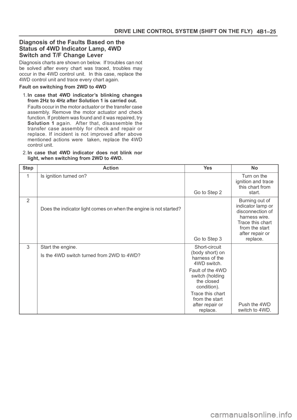
4B1–25 DRIVE LINE CONTROL SYSTEM (SHIFT ON THE FLY)
Diagnosis of the Faults Based on the
Status of 4WD Indicator Lamp, 4WD
Switch and T/F Change Lever
Diagnosis charts are shown on below. If troubles can not
be solved after every chart was traced, troubles may
occur in the 4WD control unit. In this case, replace the
4WD control unit and trace every chart again.
Fault on switching from 2WD to 4WD
1.In case that 4WD indicator’s blinking changes
from 2Hz to 4Hz after Solution 1 is carried out.
Faults occur in the motor actuator or the transfer case
assembly. Remove the motor actuator and check
function. If problem was found and it was repaired, try
Solution 1 again. After that, disassemble the
transfer case assembly for check and repair or
replace. If incident is not improved after above
mentioned actions were taken, replace the 4WD
control unit.
2.In case that 4WD indicator does not blink nor
light, when switching from 2WD to 4WD.
Step
ActionYe sNo
1Is ignition turned on?
Go to Step 2
Turn on the
ignition and trace
this chart from
start.
2
Does the indicator light comes on when the engine is not started?
Go to Step 3
Burning out of
indicator lamp or
disconnection of
harness wire.
Trace this chart
from the start
after repair or
replace.
3Start the engine.
Is the 4WD switch turned from 2WD to 4WD?Short-circuit
(body short) on
harness of the
4WD switch.
Fault of the 4WD
switch (holding
the closed
condition).
Trace this chart
from the start
after repair or
replace.
Push the 4WD
switch to 4WD.
Page 586 of 6000

4B2–15 DRIVE LINE CONTROL SYSTEM (TOD)
7. Slowly start the vehicle in the 4L mode, and
accelerate to at least 20 km/h. Apply the brake to
completely stop the vehicle.
If the CHECK lamp starts blinking during the test run, read
the trouble codes and give appropriate maintenance
according to the fault diagnostic procedure. If the TOD
indicator lamps are lit abnormally during the run, check
the lighting condition and give appropriate maintenance
according to the fault diagnostic procedure. Even if the
phenomena are not observed, try to reproduce the
abnormal state reported by the customer to the possible
extent.
Post-Repair Check
As long as the starter is not turned off, the TOD indicator
lamps continue blinking even after the failed control unit is
repaired. Therefore, upon completion of repair, be sure to
turn off the starter switch once and then turn on it to
conduct the test run sequence specified in steps 1
through 6 above and check that the TOD indicator lamps
no longer show any faulty status.
Page 669 of 6000

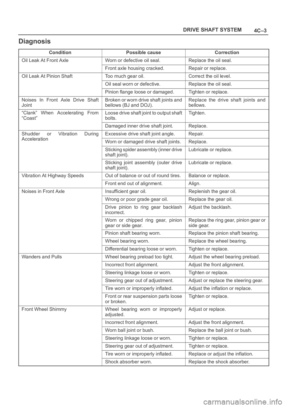
4C–3 DRIVE SHAFT SYSTEM
Diagnosis
ConditionPossible causeCorrection
Oil Leak At Front AxleWorn or defective oil seal.Replace the oil seal.
Front axle housing cracked.Repair or replace.
Oil Leak At Pinion ShaftToo much gear oil.Correct the oil level.
Oil seal worn or defective.Replace the oil seal.
Pinion flange loose or damaged.Tighten or replace.
Noises In Front Axle Drive Shaft
JointBroken or worn drive shaft joints and
bellows (BJ and DOJ).Replace the drive shaft joints and
bellows.
“Clank” When Accelerating From
“Coast”Loose drive shaft joint to output shaft
bolts.Tighten.
Damaged inner drive shaft joint.Replace.
Shudder or Vibration During
Acceleration
Excessive drive shaft joint angle.Repair.
AccelerationWorn or damaged drive shaft joints.Replace.
Sticking spider assembly (inner drive
shaft joint).Lubricate or replace.
Sticking joint assembly (outer drive
shaft joint).Lubricate or replace.
Vibration At Highway SpeedsOut of balance or out of round tires.Balance or replace.
Front end out of alignment.Align.
Noises in Front AxleInsufficient gear oil.Replenish the gear oil.
Wrong or poor grade gear oil.Replace the gear oil.
Drive pinion to ring gear backlash
incorrect.Adjust the backlash.
Worn or chipped ring gear, pinion
gear or side gear.Replace the ring gear, pinion gear or
side gear.
Pinion shaft bearing worn.Replace the pinion shaft bearing.
Wheel bearing worn.Replace the wheel bearing.
Differential bearing loose or worn.Tighten or replace.
Wanders and PullsWheel bearing preload too tight.Adjust the wheel bearing preload.
Incorrect front alignment.Adjust the front alignment.
Steering linkage loose or worn.Tighten or replace.
Steering gear out of adjustment.Adjust or replace the steering gear.
Tire worn or improperly inflated.Adjust the inflation or replace.
Front or rear suspension parts loose
or broken.Tighten or replace.
Front Wheel ShimmyWheel bearing worn or improperly
adjusted.Adjust or replace.
Incorrect front alignment.Adjust the front alignment.
Worn ball joint or bush.Replace the ball joint or bush.
Steering linkage loose or worn.Tighten or replace.
Steering gear out of adjustment.Tighten or replace.
Tire worn or improperly inflated.Replace or adjust the inflation.
Shock absorber worn.Replace the shock absorber.
Page 671 of 6000

4C–5 DRIVE SHAFT SYSTEM
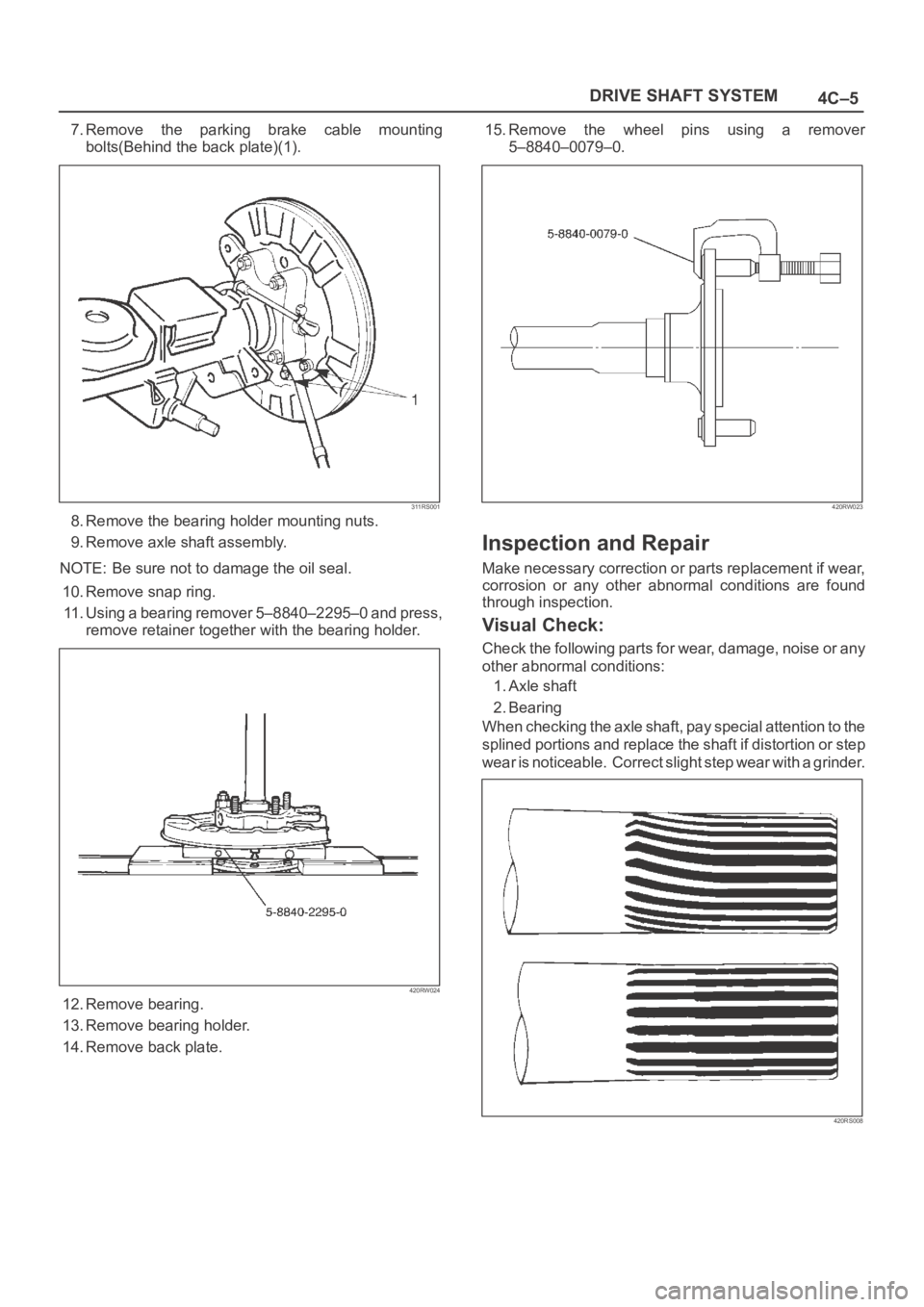
7.Remove the parking brake cable mounting
bolts(Behind the back plate)(1).
311RS001
8. Remove the bearing holder mounting nuts.
9. Remove axle shaft assembly.
NOTE: Be sure not to damage the oil seal.
10. Remove snap ring.
11. Using a bearing remover 5–8840–2295–0 and press,
remove retainer together with the bearing holder.
420RW024
12. Remove bearing.
13. Remove bearing holder.
14. Remove back plate.15. Remove the wheel pins using a remover
5–8840–0079–0.
420RW023
Inspection and Repair
Make necessary correction or parts replacement if wear,
corrosion or any other abnormal conditions are found
through inspection.
Visual Check:
Check the following parts for wear, damage, noise or any
other abnormal conditions:
1. Axle shaft
2. Bearing
When checking the axle shaft, pay special attention to the
splined portions and replace the shaft if distortion or step
wear is noticeable. Correct slight step wear with a grinder.
420RS008
Page 676 of 6000

4C–10
DRIVE SHAFT SYSTEM
8. Remove lock washer and lock screw.
9. Use wrench 5–8840–2117–0, remove hub nut.
411RW005
10. Remove hub and disc assembly.
11. Remove ABS sensor ring (If equipped).
12. Remove outer bearing.
13. Remove oil seal.
14. Remove inner bearing.
15. Remove bolt , if necessary, replace the wheel pin in
the following manner.
Apply a scribe mark(1) to disc to hub.
Clamp the hub and disc assembly in a vise, using
protective pads. Remove the 6 disc–to–hub
retaining bolts.
411RS003
Place hub on a suitable work surface and remove
the studs by using a hammer.
411RS004
Inspection and Repair
Make necessary correction or parts replacement if wear,
damage, corrosion or any other abnormal conditions are
found through inspection.
Check the following parts:
Hub
Hub bearing oil seal
Knuckle spindle
Disc
Caliper
Shift on the fly system parts (Cap, Hub flange, Shim,
Snap ring)
ABS sensor ring (If equipped)
For inspection and servicing of disc caliper and related
parts, refer to Brakes section.
Page 682 of 6000

4C–16
DRIVE SHAFT SYSTEM
Inspection and Repair
Make necessary correction or parts replacement if wear,
damage, corrosion or any other abnormal condition are
found through inspection.
Check the following parts.
Hub
Hub bearing, oil seal
Knuckle spindle
Disc
Caliper
Free wheeling hub parts (Clutch, knob, follower,
inner, ring and spring)
ABS sensor ring (if so equipped)
For inspection and servicing of disc caliper, and relative
parts, refer to Brakes section.
Reassembly
1. Install spacer.
Apply about 1 g wheel bearing grease to both face of
spacer.
2. Install ring.
Apply about 3 g wheel bearing grease to inside face
of ring.
3. Install snap ring
Assembly with grease surplus being left unwiped up
as illustrated.
411RW013
Legend
(1) Inner Assembly
(2) Apply Grease
(3) Body
4. Install inner assembly.
Apply grease to splined portion of body.
5. Install snap ring.6. Install X–ring.
Apply wheel bearing grease to hub lock ring and fit it
in knob paying attention to mounting direction.
NOTE: After fitting, make sure that the hub lock ring is not
twisted.
7. Apply wheel bearing grease to ball and spring and fit
them in knob.
8. Install knob.
1. Apply grease to outer circumference of knob and
inner circumference of cover.
2. Align detent ball (1) to a groove cut in the cover.
411RW014
9. Install snap ring.
Turn the smoother face to knob side.
10. Align the end of retaining spring (1) with clutch spring
groove (2) and fit in the spring.
411RW015
Page 691 of 6000

4C–25 DRIVE SHAFT SYSTEM
8. Using snap ring pliers, remove the snap ring (1)
fastening the ball retainer to the center shaft.
412RS013
9. Remove ball retainer, ball guide and bellows.
10. Raise the hooked end of the band (1) with a
screwdriver or equivalent.
412RS014
11. Remove band.
12. Remove bellows.
13. Remove dust seal.
14. Remove BJ shaft assembly.
15. Remove the mounting bracket fixing bolts, and then
remove DOJ case assembly from the axle case.
16. Remove snap ring and bearing.
17. Remove snap ring and oil seal.
18. Remove bracket.
Inspection and Repair
Make necessary correction or parts replacement if wear,
damage, corrosion or any other abnormal conditions are
found through inspection.
Check the following parts:
1. Drive shaft joint assembly
2. DOJ case, ball, ball guide, ball retainer
3. Bellows
4. Bearing
5. Dust seal, oil seal
Bushing Replacement
Remove the bushings using a remover
5–8840–2309–0 and hammer.
412RW051
By using installer and base 5–8840–2309–0, press fit
the bushings into the bracket.
412RW052
Page 708 of 6000

4C–42
DRIVE SHAFT SYSTEM
3. Make sure of proper position for reinstallation by
applying setting marks, then remove spider .
Inspection and Repair
Make necessary correction or parts replacement if wear,
damage, corrosion or any other abnormal condition is
found through inspection.
NOTE: When any part of the journal assembly (spider,
needle roller bearing) requires replacement, be sure to
replace the entire assembly.
Check the following parts for wear, damage, noise or any
other abnormal conditions:
1. Spider
2. Needle roller bearing
3. Yoke
4. Flange
5. Constant velocity joint
Outside Diameter of Spider Pin
Standard: 17.00 mm (0.669 in)
Limit: 16.90 mm (0.665 in)
401RS007
Propeller Shaft Run–out
Support the ends of the propeller shaft on V-blocks (2)
and check for run–out by holding the probe of a dial
indicator (1) in contact with the center part of the shaft. If
the amount of run–out is beyond the standard value for
assembly, correct with a bench press or replace the shaft
with a new propeller shaft assembly.
Standard: 0.3 mm (0.012 in)
Limit: 0.5 mm (0.02 in)
401RS027
Play in Splines in Normal Direction of
Rotation
Check the amount of play between the sleeve yoke (1)
and the propeller shaft spline (2) in the direction of
rotation, using a pointed feeler gauge.
Standard: 0.073 – 0.156 mm (0.003 – 0.006 in)
Limit: 0.3 mm (0.012 in)
401RS009
Page 718 of 6000

4C–52
DRIVE SHAFT SYSTEM
3. Make sure of proper position for reinstallation by
applying setting marks, then remove spider with
grease fitting.
Inspection and Repair
Make necessary correction or parts replacement if wear,
damage, corrosion or any other abnormal condition is
found through inspection.
NOTE: When any part of the journal assembly (spider,
needle roller bearing, grease fitting) requires
replacement, be sure to replace the entire assembly.
Check the following parts for wear, damage, noise or any
other abnormal conditions:
1. Spider
2. Needle roller bearing
3. Yoke
4. Flange
Outside Diameter of Spider Pin
Standard: 17.00 mm (0.669 in)
Limit: 16.90 mm (0.665 in)
401RS007
Propeller Shaft Run-out
Support the ends of the propeller shaft on V-blocks (2)
and check for run-out by holding the probe of a dial
indicator (1) in contact with the center part of the shaft. If
the amount of run-out is beyond the standard value for
assembly, correct with a bench press or replace the shaft
with a new propeller shaft assembly .
Standard: 0.3 mm (0.012 in)
Limit: 0.5 mm (0.02 in)
401RS008
Play in Splines in Normal Direction of
Rotation
Check the amount of play between the sleeve yoke (1)
and the propeller shaft spline (2) in the direction of
rotation, using a pointed feeler gauge.
Standard: 0.073 – 0.156 mm (0.003 – 0.006 in)
Limit: 0.3 mm (0.012 in)
401RS009
Page 754 of 6000

TRANSFER CASE (STANDARD TYPE)
4D1–33
NOTE: Do not reuse the stopper plate. (Shift On The Fly
model)
24. Disassemble the 2WD–4WD clutch hub and sleeve
assembly.
Springs (1) (Shift On The Fly model)
Inserts (2) (Shift On The Fly model)
Clutch Hub (3)
Sleeve (4)
226RW133
25. Use a bench press and the ball bearing remover
5–8840–0015–0 (J–22912–01) to remove the ball
bearing (4) from front output shaft (5).
262RW071
26. Remove bearing snap ring (29) from transfer case.
27. Remove the counter gear assembly (28) from the
transfer case (1).
28. Use a pair of snap ring pliers to remove the snap ring
(20).29. Use a bench press and the bearing remover
5–8840–0015–0 (J–22912–01) to remove the ball
bearing (21).
30. Use a pair of snap ring pliers to remove the snap ring
(27).
31. Use a bench press and the bearing remover
5–8840–0015–0 (J–22912–01) to remove the ball
bearing (26).
226RW191
32. Remove the spacer (25).
33. Remove the belleville spring (24).
34. Remove the sub–gear (anti–lash plate) (23) from the
counter gear (22).
Inspection and Repair
1. Make the necessary repair or parts replacement if
wear, damage or any other abnormal conditions are
found during inspection.
2. Wash all parts thoroughly in clean solvent. Be sure all
old lubricant, metallic particles, dirt, or foreign
material are removed from the surfaces of every part.
Apply compressed air to each oil feed port and
channel in each case half to remove any obstructions
or cleaning solvent residue.
Gears
1. Inspect all the gear teeth for signs of excessive wear
or damage and check all the gear splines for burrs,
nicks, wear or damage. Remove the minor nicks or
scratches on an oil stone. Replace any part exhibiting
excessive wear or damage.
Front Output Gear Inside Diameter
1. Use an inside dial indicator to measure the gear inside
diameter.