diesel OPEL FRONTERA 1998 Workshop Manual
[x] Cancel search | Manufacturer: OPEL, Model Year: 1998, Model line: FRONTERA, Model: OPEL FRONTERA 1998Pages: 6000, PDF Size: 97 MB
Page 217 of 6000
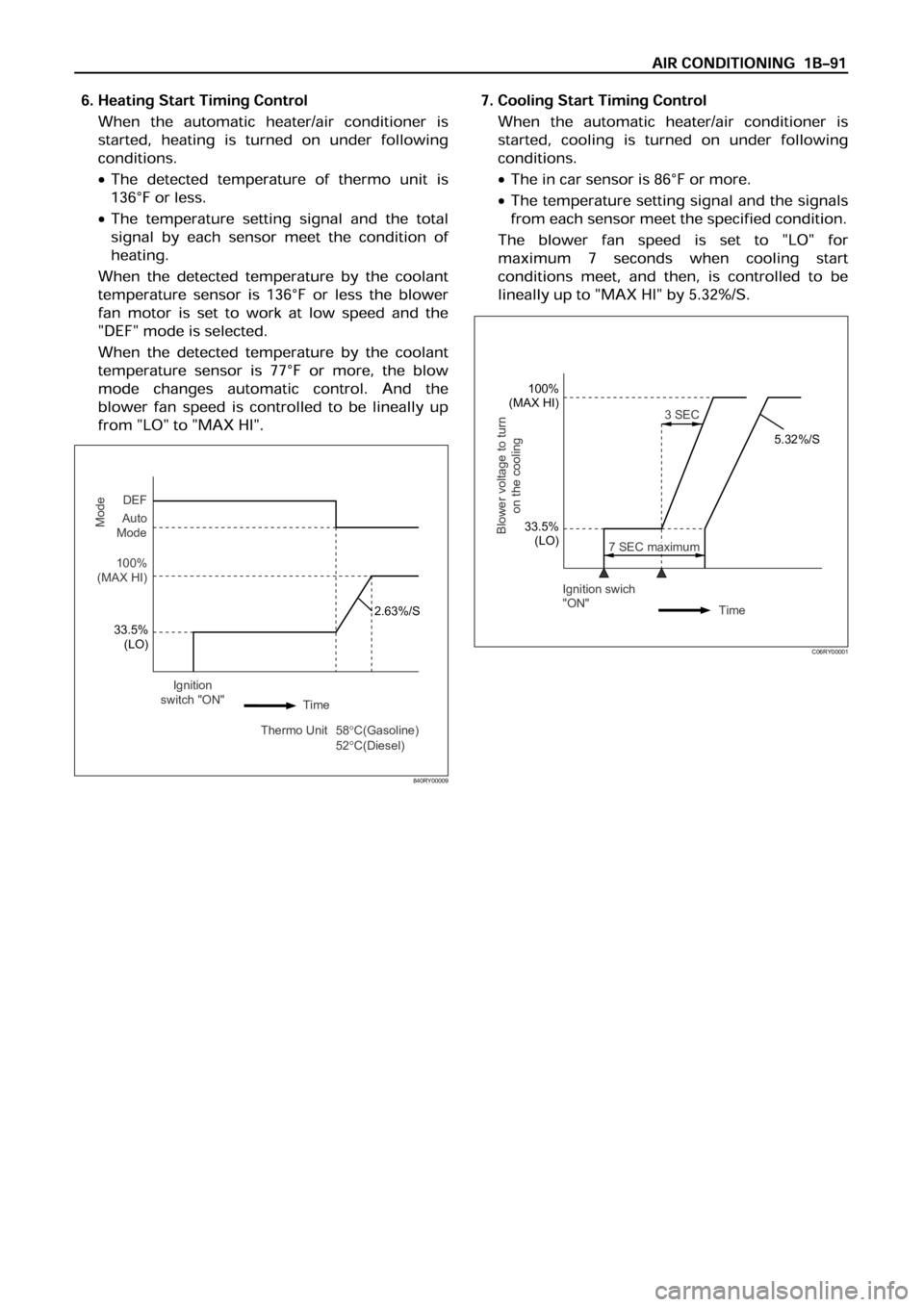
Ignition swich
"ON"
Time
Blower voltage to turn
on the cooling
7 SEC maximum3 SEC
100%
(MAX HI)
33.5%
(LO)5.32%/S
C06RY00001
33.5%
(LO)
2.63%/S
Mode
DEF
Auto
Mode
100%
(MAX HI)
Ignition
switch "ON"
Thermo Unit 58
C(Gasoline)
52C(Diesel) Time
840RY00009
Page 545 of 6000
4B1–12
DRIVE LINE CONTROL SYSTEM (SHIFT ON THE FLY)
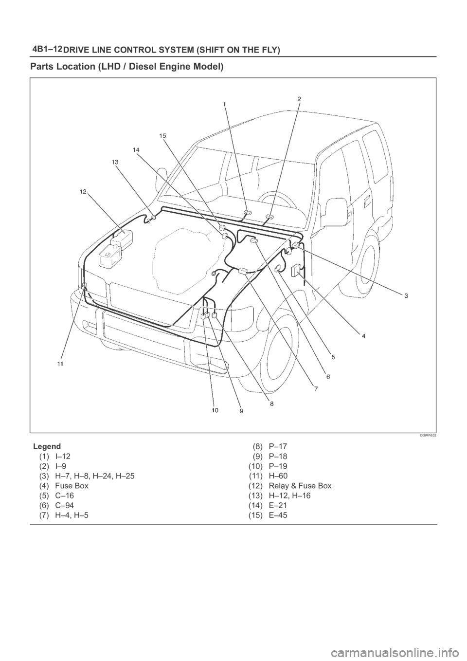
Parts Location (LHD / Diesel Engine Model)
D08RW852
Legend
(1) I–12
(2) I–9
(3) H–7, H–8, H–24, H–25
(4) Fuse Box
(5) C–16
(6) C–94
(7) H–4, H–5(8) P–17
(9) P–18
(10) P–19
(11) H–60
(12) Relay & Fuse Box
(13) H–12, H–16
(14) E–21
(15) E–45
Page 547 of 6000
4B1–14
DRIVE LINE CONTROL SYSTEM (SHIFT ON THE FLY)
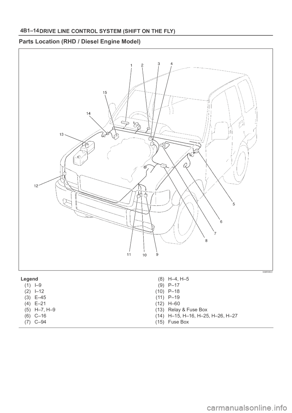
Parts Location (RHD / Diesel Engine Model)
D08RW831
Legend
(1) I–9
(2) I–12
(3) E–45
(4) E–21
(5) H–7, H–9
(6) C–16
(7) C–94(8) H–4, H–5
(9) P–17
(10) P–18
(11) P–19
(12) H–60
(13) Relay & Fuse Box
(14) H–15, H–16, H–25, H–26, H–27
(15) Fuse Box
Page 550 of 6000
4B1–17 DRIVE LINE CONTROL SYSTEM (SHIFT ON THE FLY)
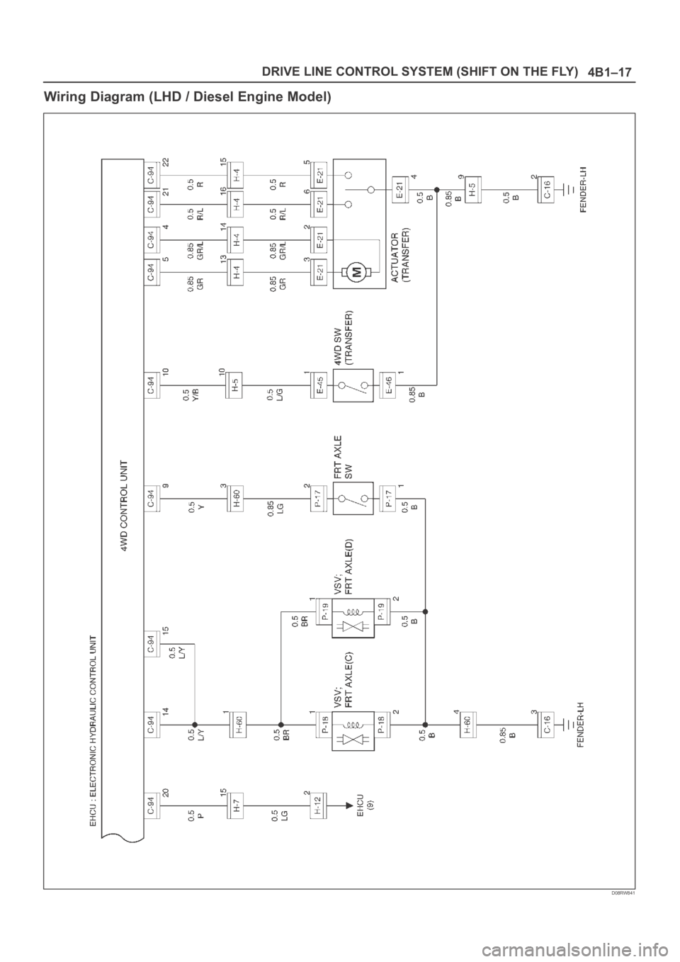
Wiring Diagram (LHD / Diesel Engine Model)
D08RW841
Page 553 of 6000
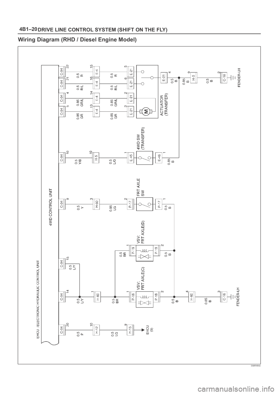
4B1–20
DRIVE LINE CONTROL SYSTEM (SHIFT ON THE FLY)
Wiring Diagram (RHD / Diesel Engine Model)
D08RW842
Page 578 of 6000
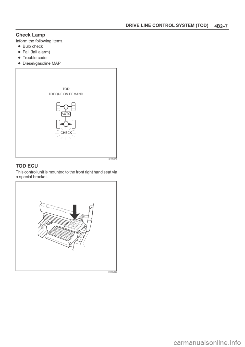
4B2–7 DRIVE LINE CONTROL SYSTEM (TOD)
Check Lamp
Inform the following items.
Bulb check
Fail (fail alarm)
Trouble code
Diesel/gasoline MAP
821RW078
TOD ECU
This control unit is mounted to the front right hand seat via
a special bracket.
F07RW029
Page 582 of 6000
4B2–11 DRIVE LINE CONTROL SYSTEM (TOD)
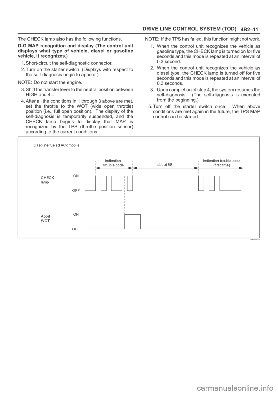
The CHECK lamp also has the following functions.
D-G MAP recognition and display (The control unit
displays what type of vehicle, diesel or gasoline
vehicle, it recognizes.)
1. Short-circuit the self-diagnostic connector.
2. Turn on the starter switch. (Displays with respect to
the self-diagnosis begin to appear.)
NOTE: Do not start the engine.
3. Shift the transfer lever to the neutral position between
HIGH and 4L.
4. After all the conditions in 1 through 3 above are met,
set the throttle to the WOT (wide open throttle)
position (i.e., full open position). The display of the
self-diagnosis is temporarily suspended, and the
CHECK lamp begins to display that MAP is
recognized by the TPS (throttle position sensor)
according to the current conditions.NOTE: If the TPS has failed, this function might not work.
1. When the control unit recognizes the vehicle as
gasoline type, the CHECK lamp is turned on for five
seconds and this mode is repeated at an interval of
0.3 second.
2. When the control unit recognizes the vehicle as
diesel type, the CHECK lamp is turned off for five
seconds and this mode is repeated at an interval of
0.3 seconds.
3. Upon completion of step 4, the system resumes the
self-diagnosis. (The self-diagnosis is executed
from the beginning.)
5. Turn off the starter switch once. When above
conditions are met again in the future, the TPS MAP
control can be started.
C04RW010
Page 615 of 6000
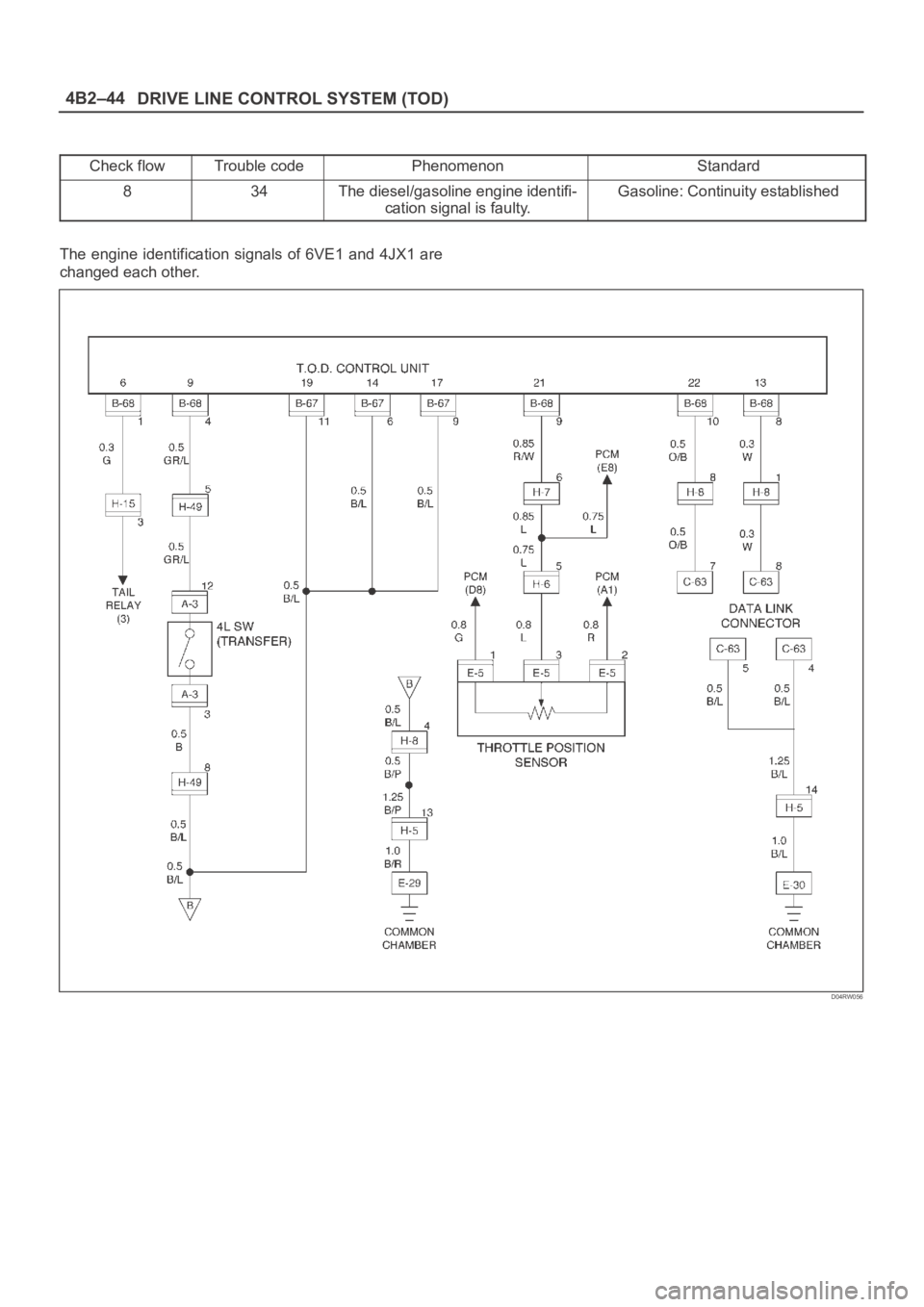
DRIVE LINE CONTROL SYSTEM (TOD) 4B2–44
Check flowTrouble codePhenomenonStandard
834The diesel/gasoline engine identifi-
cation signal is faulty.Gasoline: Continuity established
The engine identification signals of 6VE1 and 4JX1 are
changed each other.
D04RW056
Page 1070 of 6000
6C–3
ENGINE FUEL
Adhere to all Notices and Cautions.
All gasoline engines are designed to use only unleaded
gasoline. Unleaded gasoline must be used for proper
emission control system operation.
Its use will also minimize spark plug fouling and extend
engine oil life. Using leaded gasoline can damage the
emission control system and could result in loss of
emission warranty coverage.
All cars are equipped with an Evaporative Emission
Control System. The purpose of the system is to minimize
the escape of fuel vapors to the atmosphere.
Fuel Metering
The Engine Control Module (ECM) is in complete control
of this fuel delivery system during normal driving
conditions.
The intake manifold function, like that of a diesel, is used
only to let air into the engine. The fuel is injected by
separate injectors that are mounted over the intake
manifold.
The Manifold Absolute Pressure (MAP) sensor measures
the changes in the intake manifold pressure which result
from engine load and speed changes, which the MAP
sensor converts to a voltage output.
This sensor generates the voltage to change
corresponding to the flow of the air drawn into the engine.
The changing voltage is transformed into an electric
signal and provided to the ECM.
With receipt of the signals sent from the MAP sensor,
Intake Air Temperature sensor and others, the ECM
determines an appropriate fuel injection pulse width
feeding such information to the fuel injector valves to
effect an appropriate air/fuel ratio.
The Multiport Fuel Injection system utilizes an injection
system where the injectors turn on at every crankshaft
re vol u tion . Th e EC M con tro ls t he in je cto r on tim e so t ha t
the correct amount of fuel is metered depending on
driving conditions.
Two interchangeable “O” rings are used on the injector
that must be replaced when the injectors are removed.
The fuel rail is attached to the top of the intake manifold
and supplies fuel to all the injectors.
Fuel is recirculated through the rail continually while the
engine is running. This removes air and vapors from the
fuel as well as keeping the fuel cool during hot weather
operation.
The fuel pressure control valve that is mounted on the fuel
rail maintains a pressure differential across the injectors
under all operating conditions. It is accomplished by
controlling the amount of fuel that is recirculated back to
the fuel tank based on engine demand.
See Section “Driveability and Emission” for more
information and diagnosis.
Page 1396 of 6000
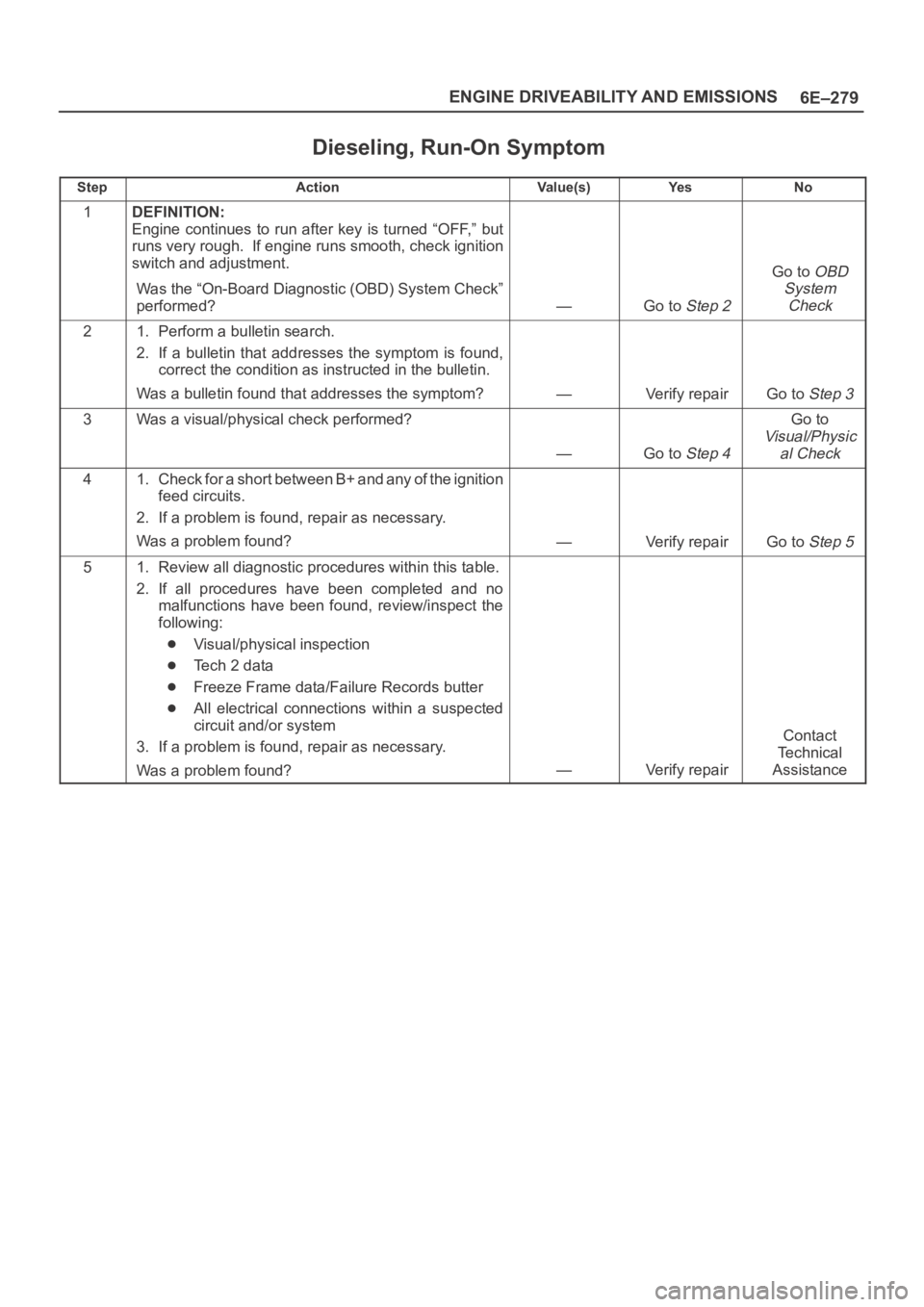
6E–279 ENGINE DRIVEABILITY AND EMISSIONS
Dieseling, Run-On Symptom
StepActionVa l u e ( s )Ye sNo
1DEFINITION:
Engine continues to run after key is turned “OFF,” but
runs very rough. If engine runs smooth, check ignition
switch and adjustment.
Was the “On-Board Diagnostic (OBD) System Check”
performed?
—Go to Step 2
Go to OBD
System
Check
21. Perform a bulletin search.
2. If a bulletin that addresses the symptom is found,
correct the condition as instructed in the bulletin.
Was a bulletin found that addresses the symptom?
—Verify repairGo to Step 3
3Was a visual/physical check performed?
—Go to Step 4
Go to
Visual/Physic
al Check
41. Check for a short between B+ and any of the ignition
feed circuits.
2. If a problem is found, repair as necessary.
Was a problem found?
—Verify repairGo to Step 5
51. Review all diagnostic procedures within this table.
2. If all procedures have been completed and no
malfunctions have been found, review/inspect the
following:
Visual/physical inspection
Te c h 2 d a t a
Freeze Frame data/Failure Records butter
All electrical connections within a suspected
circuit and/or system
3. If a problem is found, repair as necessary.
Was a problem found?
—Verify repair
Contact
Te c h n i c a l
Assistance