weight OPEL GRANDLAND X 2019 Manual user
[x] Cancel search | Manufacturer: OPEL, Model Year: 2019, Model line: GRANDLAND X, Model: OPEL GRANDLAND X 2019Pages: 277, PDF Size: 7.75 MB
Page 64 of 277

62Seats, restraintsEither a Top-tether strap or a supportleg must be used in addition to the
ISOFIX mounting brackets.
i-size child seats and vehicle seats
with i-size approval are marked with
i-size symbol, see illustration.
Top-tether anchors Top-tether anchors are marked with
the symbol : for a child seat.
In addition to the ISOFIX mounting
brackets, fasten the Top-tether strap
to the Top-tether anchors.
ISOFIX child restraint systems of
universal category positions are
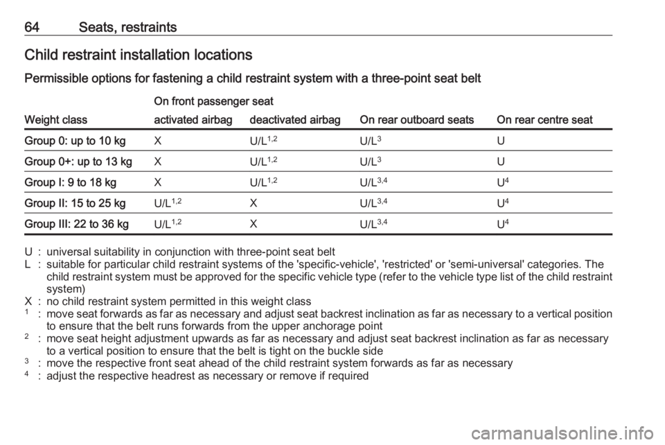
marked in the table by IUF 3 64.
Selecting the right system The rear seats are the most
convenient location to fasten a child
restraint system.
Children should travel facing
rearwards in the vehicle as long as
possible. This makes sure that the child's backbone, which is still very
weak, is under less strain in the event of an accident.
Suitable are child restraint systems
that comply with valid UN ECE
regulations. Check local laws and
regulations for mandatory use of child
restraint systems.The following child restraints are
recommended for the following
weight classes:
● Group 0, Group 0+ :
Maxi Cosi Cabriofix with or without ISOFIX base for children
up to 13 kg
● Group I : Duo Plus with ISOFIX
and Top-tether for children from 9 kg to 18 kg
● Group II, Group III : Kidfix XP with
or without ISOFIX for children
from 15 kg to 36 kg
● Group III : Graco Booster for
children from 22 kg to 36 kg
Ensure that the child restraint system to be installed is compatible with the
vehicle type.
Ensure that the mounting location of
the child restraint system within the
vehicle is correct, see following
tables.
Allow children to enter and exit the
vehicle only on the side facing away
from the traffic.
When the child restraint system is not in use, secure the seat with a seat beltor remove it from the vehicle.
Page 66 of 277

64Seats, restraintsChild restraint installation locations
Permissible options for fastening a child restraint system with a three-point seat belt
Weight class
On front passenger seat
On rear outboard seatsOn rear centre seat
activated airbagdeactivated airbagGroup 0: up to 10 kgXU/L 1,2U/L 3UGroup 0+: up to 13 kgXU/L1,2U/L3UGroup I: 9 to 18 kgXU/L1,2U/L3,4U4Group II: 15 to 25 kgU/L 1,2XU/L3,4U4Group III: 22 to 36 kgU/L 1,2XU/L3,4U4U:universal suitability in conjunction with three-point seat beltL:suitable for particular child restraint systems of the 'specific-vehicle', 'restricted' or 'semi-universal' categories. The
child restraint system must be approved for the specific vehicle type (refer to the vehicle type list of the child restraint
system)X:no child restraint system permitted in this weight class1:move seat forwards as far as necessary and adjust seat backrest inclination as far as necessary to a vertical position to ensure that the belt runs forwards from the upper anchorage point2:move seat height adjustment upwards as far as necessary and adjust seat backrest inclination as far as necessaryto a vertical position to ensure that the belt is tight on the buckle side3:move the respective front seat ahead of the child restraint system forwards as far as necessary4:adjust the respective headrest as necessary or remove if required
Page 67 of 277

Seats, restraints65Permissible options for fitting an ISOFIX child restraint system with ISOFIX brackets
Weight classSize classFixture
On front passenger seatOn rear outboard
seatsOn rear centre
seatactivated airbagdeactivated airbagGroup 0: up to 10 kgGISO/L2XXXXFISO/L1XXXXEISO/R1XILIL 3XGroup 0+: up to 13 kgEISO/R1XILIL 3XDISO/R2XILIL3XCISO/R3XILIL3XGroup I: 9 to 18 kgDISO/R2XILIL3,4XCISO/R3XILIL3,4XBISO/F2XIL, IUFIL, IUF 3,4XB1ISO/F2XXIL, IUFIL, IUF3,4XAISO/F3XIL, IUFIL, IUF 3,4XGroup II: 15 to 25 kgXXIL3,4XGroup III: 22 to 36 kgXXIL3,4X
Page 68 of 277

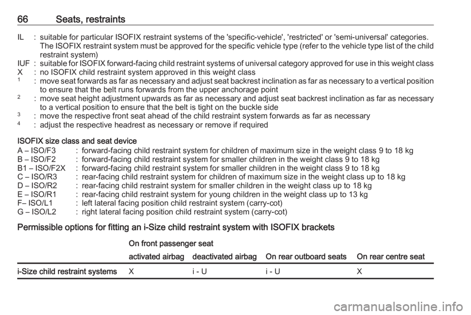
66Seats, restraintsIL:suitable for particular ISOFIX restraint systems of the 'specific-vehicle', 'restricted' or 'semi-universal' categories.
The ISOFIX restraint system must be approved for the specific vehicle type (refer to the vehicle type list of the child restraint system)IUF:suitable for ISOFIX forward-facing child restraint systems of universal category approved for use in this weight classX:no ISOFIX child restraint system approved in this weight class1:move seat forwards as far as necessary and adjust seat backrest inclination as far as necessary to a vertical positionto ensure that the belt runs forwards from the upper anchorage point2:move seat height adjustment upwards as far as necessary and adjust seat backrest inclination as far as necessary
to a vertical position to ensure that the belt is tight on the buckle side3:move the respective front seat ahead of the child restraint system forwards as far as necessary4:adjust the respective headrest as necessary or remove if required
ISOFIX size class and seat device
A – ISO/F3:forward-facing child restraint system for children of maximum size in the weight class 9 to 18 kgB – ISO/F2:forward-facing child restraint system for smaller children in the weight class 9 to 18 kgB1 – ISO/F2X:forward-facing child restraint system for smaller children in the weight class 9 to 18 kgC – ISO/R3:rear-facing child restraint system for children of maximum size in the weight class up to 18 kgD – ISO/R2:rear-facing child restraint system for smaller children in the weight class up to 18 kgE – ISO/R1:rear-facing child restraint system for young children in the weight class up to 13 kgF– ISO/L1:left lateral facing position child restraint system (carry-cot)G – ISO/L2:right lateral facing position child restraint system (carry-cot)
Permissible options for fitting an i-Size child restraint system with ISOFIX brackets
On front passenger seat
On rear outboard seatsOn rear centre seat
activated airbagdeactivated airbagi-Size child restraint systemsXi - Ui - UX
Page 78 of 277

76StorageVehicles without roof railing
Open all doors.
Mounting points are located in each
door frame of the vehicle body.
Detach the cover from each mounting
point and fasten the roof rack with the attached screws.
Loading information
● Heavy objects in the load compartment should be placed
against the seat backrests. Make
sure that the backrests are
securely engaged. If objects can
be stacked, heavier objects
should be placed at the bottom.
● Prevent sliding of loose objects by securing them with straps
attached to the lashing eyes
3 73.
● Do not allow the load to protrude above the upper edge of the
backrests.
● Do not place any objects on the load compartment cover or theinstrument panel, and do notcover the sensor on top of the
instrument panel.
● The load must not obstruct the operation of the pedals, parking
brake and gear selector, or
hinder the freedom of movement of the driver. Do not place any
unsecured objects in the interior.
● Do not drive with an open load compartment.9Warning
Always make sure that the load in
the vehicle is securely stowed.
Otherwise objects can be thrown
around inside the vehicle and
cause personal injury or damage
to the load or car.
● The payload is the difference between the permitted gross
vehicle weight (see identification
plate 3 246) and the EC kerb
weight.
Page 79 of 277

Storage77To calculate the payload, enter
the data for your vehicle in the
weights table at the front of this
manual.
The EC kerb weight includes
weights for the driver (68 kg),
luggage (7 kg) and all fluids (fuel
tank 90% full).
Optional equipment and
accessories increase the kerb
weight.
● Driving with a roof load increases
the sensitivity of the vehicle to
cross-winds and has a
detrimental effect on vehicle
handling due to the vehicle's
higher centre of gravity.
Distribute the load evenly and secure it properly with retaining
straps. Adjust the tyre pressure
and vehicle speed according to
the load conditions. Check and
retighten the straps frequently.
Do not drive faster than
120 km/h.
The permissible roof load is
85 kg. The roof load is the
combined weight of the roof rack and the load.
Page 157 of 277

Driving and operating155Deactivation
ESC and TC can be deactivated,
everytime it is required: press a.
The LED in the button a illuminates.
A status message appears in the
Driver Information Centre when ESC
and TC are deactivated.
ESC and TC are reactivated by
pressing the a button again, by
applying the brake or in the case that
the vehicle is driven faster than
50 km/h.
The LED in the button a extinguishes
when ESC and TC are reactivated.
ESC and TC are also reactivated the
next time the ignition is switched on.
Fault
If there is a fault in the system, the control indicator b illuminates
continuously and a message appears
in the Driver Information Centre. The
system is not operational.
Have the cause of the fault remedied
by a workshop.
Selective ride controlCaution
The vehicle is designed to drive
principally on-road, but it also
enables driving off-road
occasionally.
However, do not drive on terrain
where the vehicle could be
damaged due to obstacles, such
as stones among others and on
terrain with steep inclines and
poor grip.
Do not cross waters.
Caution
When driving off-road, sudden
motion and manoeuvres can
cause a collision or losing control.
Selective ride control is designed to
optimise traction in low-grip
conditions (snow, mud and sand).
It adapts to the terrain by acting on the
front wheels, in doing so this saves
the weight normally associated with a more conventional four wheel drive
system.
Page 198 of 277

196Driving and operatingTo close, turn the fuel filler cap
clockwise until it clicks.
Close the flap and allow it to engage.
Fuel filler cap
Only use genuine fuel filler caps.
Diesel-engined vehicles have special fuel filler caps.Trailer hitch
General information
Only use towing equipment that has
been approved for your vehicle. If
using non-factory fitted towing
equipment, deactivation of the hands- free tailgate operation may be
required 3 30.
Entrust retrofitting of towing
equipment to a workshop. It may be
necessary to make changes that
affect the cooling system, heat
shields or other equipment.
The bulb outage detection function for
trailer brake light cannot detect a
partial bulb outage. E.g. in case of
four bulbs with a power of 5 W each,
the function only detects lamp outage when only a single 5 W lamp remains
or none remain.
Trailers equipped with LED lights are
not suitable for the wiring harness of
this trailer hitch.
Fitting of towing equipment could
cover the opening of the towing eye.
If this is the case use the coupling ballbar for towing. Always keep the
coupling ball bar in the vehicle to have it on hand if needed.
Driving characteristics andtowing tips
Before attaching a trailer, lubricate
the coupling ball. However, do not do
so if a stabiliser, which acts on the coupling ball, is being used to reduce snaking movements.
During trailer towing do not exceed a
speed of 80 km/h. A maximum speed
of 100 km/h is only appropriate if an
oscillation damper is used and the
permissible gross trailer weight does
not exceed the vehicle’s curb weight.
For trailers with low driving stability
and caravan trailers, the use of an
oscillation damper is strongly
recommended.
If the trailer starts snaking, drive more
slowly, do not attempt to correct the
steering and brake sharply if
necessary.
When driving downhill, drive in the
same gear as if driving uphill and
drive at a similar speed.
Page 199 of 277

Driving and operating197Adjust tyre pressure to the value
specified for full load 3 257.
Trailer towing Trailer loadsThe permissible trailer loads are
vehicle and engine-dependent
maximum values which must not be
exceeded. The actual trailer load is
the difference between the actual
gross weight of the trailer and the
actual coupling socket load with the
trailer coupled.
The permissible trailer loads are
specified in the vehicle documents. In general, they are valid for gradients
up to 12%.
The permissible trailer load applies
up to the specified incline and at sea
level. Since engine power decreases
as altitude increases due to the air becoming thinner, therefore reducing
climbing ability, the permissible gross
train weight also decreases by 10%
for every 1000 m of altitude. The
gross train weight does not have to bereduced when driving on roads with
slight inclines (less than 8%, e.g.
motorways).
The permissible gross train weight must not be exceeded. This weight is
specified on the identification plate
3 246.
Vertical coupling load
The vertical coupling load is the load
exerted by the trailer on the coupling
ball. It can be varied by changing the
weight distribution when loading the
trailer.
The maximum permissible vertical
coupling load (70 kg) is specified on
the towing equipment identification
plate and in the vehicle documents.
Always aim for the maximum vertical
coupling load, especially in the case
of heavy trailers. The vertical coupling load should never fall below 25 kg.Rear axle load
When the trailer is coupled and the
towing vehicle fully loaded, the
permissible rear axle load (see
identification plate or vehicle
documents) may be exceeded by
60 kg , the gross vehicle weight rating
must not be exceeded. If the
permissible rear axle load is
exceeded, a maximum speed of
100 km/h applies.
Towing equipmentCaution
When operating without a trailer,
remove the coupling ball bar.
Page 223 of 277

Vehicle care221Tyre designations
E.g. 225/55 R 18 98 V225:tyre width, mm55:cross-section ratio (tyre height
to tyre width), %R:belt type: RadialRF:type: RunFlat18:wheel diameter, inches98:load index e.g. 98 is equivalent to 750 kgV:speed code letter
Speed code letter:
Q:up to 160 km/hS:up to 180 km/hT:up to 190 km/hH:up to 210 km/hV:up to 240 km/hW:up to 270 km/h
Choose a tyre appropriate for the
maximum speed of your vehicle.
The maximum speed is achievable at
kerb weight with driver (75 kg) plus
125 kg payload. Optional equipment
could reduce the maximum speed of
the vehicle.
Performance 3 253.
Directional tyres
Directional tyres should be mounted
so that they rotate in the correct
direction. The proper rotation
direction is indicated by a symbol (e.g. an arrow) on the sidewall.
Tyre pressure
Check the pressure of cold tyres at
least every 14 days and before any
long journey. Do not forget the spare
wheel. This also applies to vehicles
with tyre pressure monitoring system.
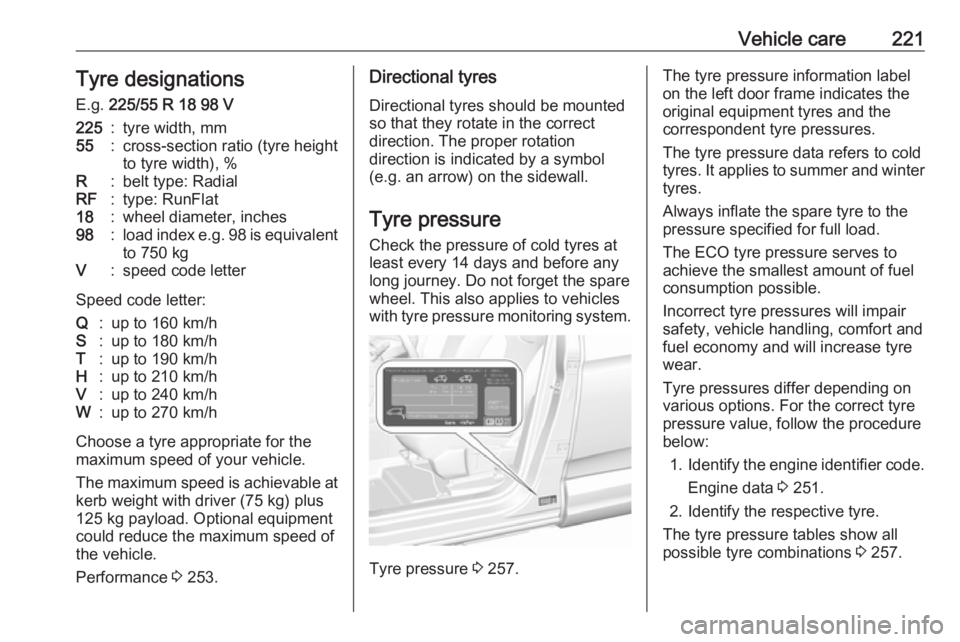
Tyre pressure 3 257.
The tyre pressure information label
on the left door frame indicates the
original equipment tyres and the
correspondent tyre pressures.
The tyre pressure data refers to cold
tyres. It applies to summer and winter tyres.
Always inflate the spare tyre to the
pressure specified for full load.
The ECO tyre pressure serves to
achieve the smallest amount of fuel
consumption possible.
Incorrect tyre pressures will impair
safety, vehicle handling, comfort and
fuel economy and will increase tyre
wear.
Tyre pressures differ depending on
various options. For the correct tyre
pressure value, follow the procedure
below:
1. Identify the engine identifier code.
Engine data 3 251.
2. Identify the respective tyre.
The tyre pressure tables show all
possible tyre combinations 3 257.