run flat OPEL GT-R 1973 Service Manual
[x] Cancel search | Manufacturer: OPEL, Model Year: 1973, Model line: GT-R, Model: OPEL GT-R 1973Pages: 625, PDF Size: 17.22 MB
Page 18 of 625
LUBRICATION AND MAINTENANCE OC-9
4. Remove dipstick and wipe clean.
5. Reinsert dipstick untip cap seats.
6. Remove dipstick and note reading.
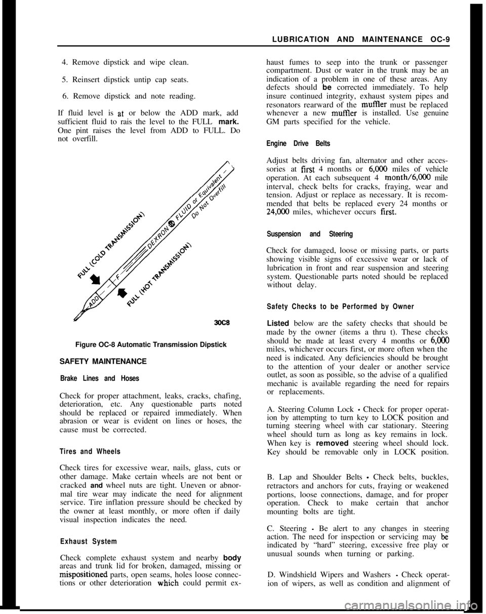
If fluid level is at, or below the ADD mark, add
sufficient fluid to rais the level to the FULL mark.
One pint raises the level from ADD to FULL. Do
not overfill.
3OC8Figure OC-8 Automatic Transmission Dipstick
SAFETY MAINTENANCE
Brake Lines and HosesCheck for proper attachment, leaks, cracks, chafing,
deterioration, etc. Any questionable parts noted
should be replaced or repaired immediately. When
abrasion or wear is evident on lines or hoses, the
cause must be corrected.
Tires and WheelsCheck tires for excessive wear, nails, glass, cuts or
other damage. Make certain wheels are not bent or
cracked and wheel nuts are tight. Uneven or abnor-
mal tire wear may indicate the need for alignment
service. Tire inflation pressure should be checked by
the owner at least monthly, or more often if daily
visual inspection indicates the need.
Exhaust SystemCheck complete exhaust system and nearby body
areas and trunk lid for broken, damaged, missing orm&positioned parts, open seams, holes loose connec-
tions or other deterioration wiuch could permit ex-haust fumes to seep into the trunk or passenger
compartment. Dust or water in the trunk may be an
indication of a problem in one of these areas. Any
defects should be corrected immediately. To help
insure continued integrity, exhaust system pipes and
resonators rearward of the muftler must be replaced
whenever a new mufIler is installed. Use genuine
GM parts specified for the vehicle.
Engine Drive BeltsAdjust belts driving fan, alternator and other acces-
sories at first 4 months or
6,ooO miles of vehicle
operation. At each subsequent 4 month/6,000 mile
interval, check belts for cracks, fraying, wear and
tension. Adjust or replace as necessary. It is recom-
mended that belts be replaced every 24 months or
24,C00 miles, whichever occurs first.
Suspension and SteeringCheck for damaged, loose or missing parts, or parts
showing visible signs of excessive wear or lack of
lubrication in front and rear suspension and steering
system. Questionable parts noted should be replaced
without delay.
Safety Checks to be Performed by OwnerListed below are the safety checks that should be
made by the owner (items a thru t). These checks
should be made at least every 4 months or
6,ooOmiles, whichever occurs first, or more often when the
need is indicated. Any deficiencies should be brought
to the attention of your dealer or another service
outlet, as soon as possible, so the advise of a qualified
mechanic is available regarding the need for repairs
or replacements.
A. Steering Column Lock
_ Check for proper operat-
ion by attempting to turn key to LOCK position and
turning steering wheel with car stationary. Steering
wheel should turn as long as key remains in lock.
When key is removed steering wheel should lock.
Key should be removable only in LOCK position.
B. Lap and Shoulder Belts
- Check belts, buckles,
retractors and anchors for cuts, fraying or weakened
portions, loose connections, damage, and for proper
operation. Check to make certain that anchor
mounting bolts are tight.
C. Steering
- Be alert to any changes in steering
action. The need for inspection or servicing may
beindicated by “hard” steering, excessive free play or
unusual sounds when turning or parking.
D. Windshield Wipers and Washers
- Check operat-
ion of wipers, as well as condition and alignment of
Page 32 of 625
I
STARTING SYSTEMlB- 11
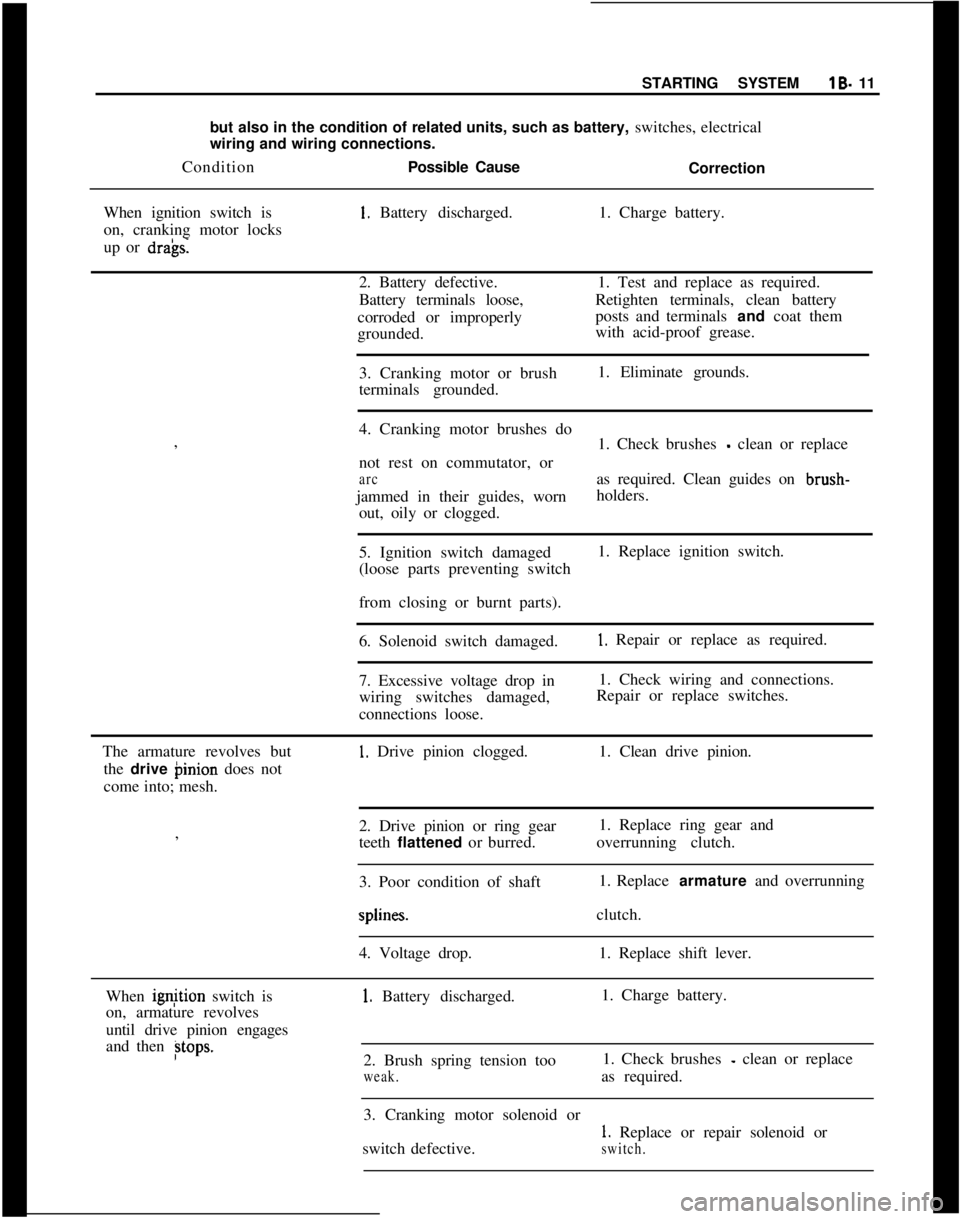
but also in the condition of related units, such as battery, switches, electrical
wiring and wiring connections.
ConditionPossible Cause
Correction
When ignition switch is1. Battery discharged.1. Charge battery.
on, cranking motor locks
up or
dra’gs.2. Battery defective.1. Test and replace as required.
Battery terminals loose,Retighten terminals, clean battery
corroded or improperlyposts and terminals and coat them
grounded.with acid-proof grease.
3. Cranking motor or brush1. Eliminate grounds.
terminals grounded.
I
4. Cranking motor brushes do
,
1. Check brushes
- clean or replace
not rest on commutator, or
arcas required. Clean guides on brush-
jammed in their guides, wornholders.
out, oily or clogged.
5. Ignition switch damaged1. Replace ignition switch.
(loose parts preventing switch
I
from closing or burnt parts).
6. Solenoid switch damaged.
1. Repair or replace as required.
7. Excessive voltage drop in1. Check wiring and connections.
wiring switches damaged,Repair or replace switches.
connections loose.
The armature revolves but
1. Drive pinion clogged.1. Clean drive pinion.
the drive binion does not
come into; mesh.
2. Drive pinion or ring gear1. Replace ring gear and
,
teeth flattened or burred.overrunning clutch.
I
3. Poor condition of shaft1. Replace armature and overrunningsplines.clutch.
4. Voltage drop.1. Replace shift lever.
When ignjtion switch is
1. Battery discharged.1. Charge battery.
on, armature revolves
until drive pinion engages
and then
Btops.2. Brush spring tension too1. Check brushes - clean or replace
weak.as required.
3. Cranking motor solenoid or
1. Replace or repair solenoid or
switch defective.
switch.
Page 33 of 625
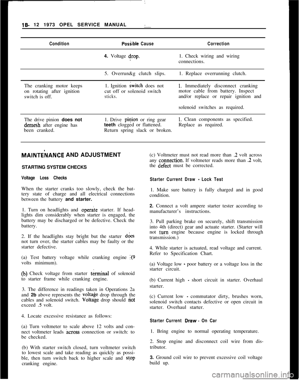
19- 12 1973 OPEL SERVICE MANUAL :ConditionPosiible CauseCorrection4. Voltage drop.1. Check wiring and wiring
connections.
5. Overrun&g clutch slips.1. Replace overrunning clutch.
The cranking motor keeps
on rotating after ignition
switch is off.1. Ignition
{witch does not
cut off or solenoid switch
sticks.
1, Immediately disconnect cranking
motor cable from battery. Inspect
and/or replace or repair ignition and
solenoid switches as required.
The drive pinion does notdemesh after engine has
been cranked.1. Drive pinion or ring gear
1. Clean components as specified.
teeth clogged or flattened.Replace as required.
Return spring slack or broken.MAlNTEilANCE AND ADJUSTMENT
/
STARTING SYSTEM CHECKS
Voltage Loss ChecksWhen the starter cranks too slowly, check the bat-
tery state of charge and all electrical connections
between the battery and starter.
1. Turn on headlights and
opera’te starter. If head-
lights dim considerably when starter is engaged, the
battery may be discharged or be defective. Check the
battery.
2. If the headlights stay bright but the starter d&s
not turn over, the starter cables may be faulty or the
starter defective.
(a) Test battery voltage while cranking engine
1(9volts minimum).
(b) Check voltage from starter tkrminal of solenoid
to starter frame while cranking engine.
3. The difference in readings taken in Operations 2a
and 2b above represents the
volt& drop through the
cables and solenoid switch. Voltdge drop should
Gotexceed
.5 volt.
4. Locate excessive resistance as follows:
(a) Turn voltmeter to scale above 12 volts and con-
nect voltmeter leads
across connection or switch: to
be checked.
(b) With starter switch closed, turn voltmeter switch
to lowest scale and take reading as quickly as possi-
ble, then turn switch back to higher scale and stop
cranking engine.(c) Voltmeter must not read more than
.2 volt across
any
c:onnection. If voltmeter reads more than .2 volt,
the
d~efect must be corrected.
Starter Current Draw - Lock Test1. Make sure battery is fully charged and in good
condition.
2. Connect a volt ampere starter tester according to
manufacturer’s instructions.
3. Pull parking brake on securely, shift transmission
into 4th (direct) gear and actuate starter. (Starter will
not
t,urn engine because engine is locked through
transmission.)
4. While starter is actuated, read voltage and current.
Refer to Specification Chart.
(a) Voltage low
_ poor battery or a voltage loss in the
starter circuit.
(b) Current high
- short circuit in starter. Overhaul
starter.
(c) Current low
- commutator dirty, brushes worn,
solenoid switch contacts defective or open circuit in
starter. Overhaul starter.
Starter Current Draw. On Car1. Bring engine to normal operating temperature.
2. Stop engine and disconnect coil wire from dis-
tributor.
3. Ground coil wire to prevent excessive coil voltage
build up.
Page 67 of 625
1F. 46 1973 OPEL SERVICE MANUAL
’
/
Headlight High-Low Beam Control and Passing:
SignalI
When the headlights have been switched on, high
and low beam selection is made by raising the direc-
tional signal lever toward steering wheel. Each
ti&the lever is raised, beam position, will change.
When the headlights are not on, a flashing headlight
signal may be given by raising and lotiering the di-
rectional signal lever. With the headlights on and
inlow beam position, raising and lowering the direc-
tional signal lever will also cause the headlights to
flash.
Fog Light SwitchAll Rallye models are equipped with two white f?g
lights mounted below the front bumper.
The fog light toggle switch is located on the
insty-ment cluster to the left of the temperature and
fuelgauge cluster.
/
The fog lights can be turned off at any time by the
toggle switch, but can only be tyrned on when: :
1. The ignition switch on or the
?gine running.!
2. The fog light toggle switch lower half is pushed
in.3. The parking lights and/or low beam headlights
are
OKThe fog lights are automatically turned off if the
ignition switch is on and the headlights are switched
to high beam position.
Courtesy LightThe courtesy light illuminates the interior of the Car
when any door is opened. The courtesy light can also
be turned on with all doors closed by tilting the l&s.
GT Headlamp MechanismThe concealed headlamps are moved mechanically.
Pushing actuating lever on left side of console opens
headlamps and pulling lever closes headlamps. Two
(2) meshing gear segments convert the movement, of
the lever to a rotation of 180 degrees. The pivots of
the headlamps lie below the centerline so that with
headlamps in closed position, the headlamp housing
is flush with front sheet metal. Refer to Group 110,
Section “F”, for service procedures on the GT head-
lamp mechanism.
A white indicator lamp in the instrument panel lights
if the headlamps are not completely opened lorclosed The switches of the headlamp electrical sys-
tem are located behind the left headlamp operating,
mechanism.
MAINTENANCE AND ADJUSTMENTSHEADLAMP AIMING
The headlamps must be properly aimed in order to
obtain maximum road illumination and safety that
has been built into the headlighting equipment. With
the Guide T-3 type sealed beam units, proper aiming
is even more important because the increased range
and power of this lamp make even slight variations
from recommended aiming hazardous to approach-
ing motorists. The headlamps must be checked for
proper aim whenever a sealed beam unit is replaced
and after an adjustment or repairs of the front end
sheet metal assembly.
Regardless of method used for checking headlamp
aim, car must be at normal weight, that is, with gas,
oil, water, and spare tire. Tires must be uniformly
inflated to specified pressure. If car will regularly
carry an unusual load in rear compartment, or a
trailer, these loads should be on car when headlamps
are checked. Some States have special requirements
for headlamp aiming adjustment, and these require-
ments should be known and observed.
Horizontal and vertical aiming of each seal beam
unit is provided by two adjusting screws which move
the mounting ring in the body against the tension of
the coil spring. There is no adjustment for focus,
since the sealed beam unit is set for proper focus
during manufacturing assembly.
MAJOR REPAIRHEADLIGHT SWITCH
- OPEL 1900. MANTA
Removal1. Remove instrument cluster cover panel. See Sec-
tion H.
2. Compress retaining springs and pull switch out.
See Figure 1 F-
1.3. Pull multiple socket off switch.
Installation
1: Plug multiple socket in switch and push switch in
panel until clips lock in place.
2. Replace instrument cover and secure with two (2)
screws.
Page 148 of 625
ROOF AND SUN ROOFZF-25ConditionCallseCorrectionSun roof lifts up on one
side only.Lifter wedge welded to under-
Remove sun roof panel and bend
side of sun roof panel doeslifter wedge so that it squarely hits
not run up ramp welded inramp. The only adjustment for
center of sun roof track.the ramp is the angle of the
rear portion. This should be
adjusted so that the wedge smoothly
rides up the ramp.
Transporter cable or drive
pinion damaged.If the transporter cable is worn
or damaged, replace both
cables. If drive pinion worn or
damaged, replace drive pinion and
also both transporter cables.
Sun roof scrapes on car roof
when closing sun roof.Lifters do not lie flat.Close sun roof, slide sun roof
frame to the rear and open and close
sun roof slightly noting operation
of lifters. Rework if necessary,plastjc lifter cushion with tile
to permit lifter to lie flat.
Sparingly lubricate lifter guide.
Sun roof frame becomes
detached.Attaching clips have lost
elasticity.Install new clips
Water enters car interior.
Water drain hoses blocked.
Bent water drain hoses
Rear water drain hoses have
been pulled out of rubber
grommets.
Velvet strips on front and
rear of sun roof do not seal
properly.Clean hoses with compressed air
or a flexible steel cable.
NOTE: To clear rear water
drain hoses, the sun roof panel
and frame must be removed.
Blowing out of rear drain hoses
from trunk compartment hose end
is not recommended due to
possibility of soiling car
interior.
Attempt to straighten drain
hoses by working a suitable
tube or cable through hose.
Replace hose if above corrective
action is not satisfactory.
Apply a small amount of rubber
cement to rear water drain
hoses and reinsert into rubber
grommet located in luggage
compartment floor panel.
Check sun roof for correct
height adjustment. If height
adjustment is correct, but a
tight seal does not exist,
relocate velvet strip upward
for better seal, or replace
velvet strip.
Page 190 of 625
FRONT END ALIGNMENT 3C-23
ing geometry, the following checks and inspections
must be made to insure correctness of alignment
equipment readings and alignment adjustments.
1. The front tires should have approximately the
same wear and all tires must be inflated to specified
pressures (see Wheel and Tire Specifications
- Sec-
tion 3G).
2. Check front wheel bearings for looseness and ad-
just if necessary (see Front Suspension Adjustments
- Section 3A).
3. Check for run-out of wheels and tires, (see Section
3G).
4. Check wheels and tires for balance and correct if
out-of-balance (See Section 3G).
5. Check for looseness at ball joints and tie
rdd ends;
if found excessive, it must be
corxcted before align-
ment readings will have any value.
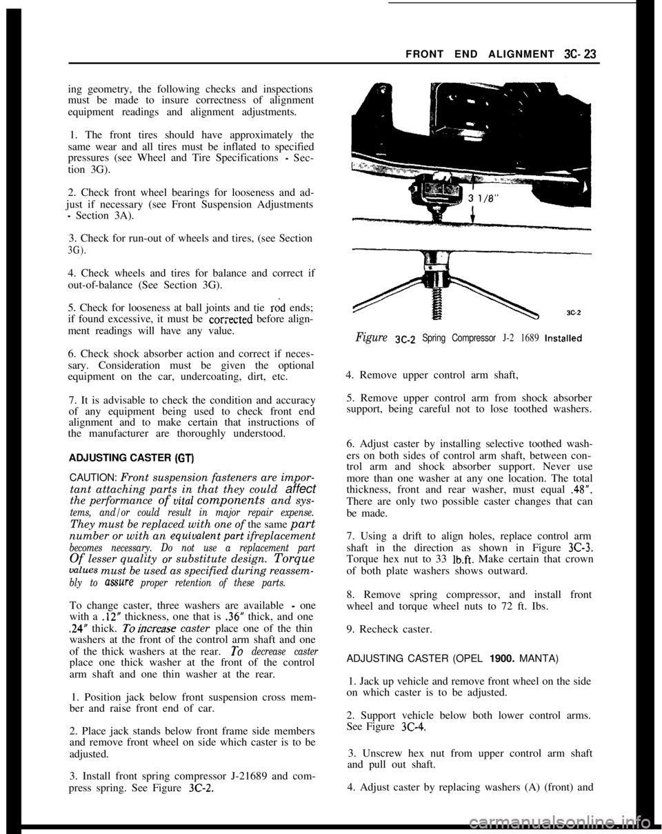
Figure SC-Z Spring Compressor J-2 1689 Installed
6. Check shock absorber action and correct if neces-
sary. Consideration must be given the optional
equipment on the car, undercoating, dirt, etc.
7. It is advisable to check the condition and accuracy
of any equipment being used to check front end
alignment and to make certain that instructions of
the manufacturer are thoroughly understood.
ADJUSTING CASTER (GT)
4. Remove upper control arm shaft,
5. Remove upper control arm from shock absorber
support, being careful not to lose toothed washers.
6. Adjust caster by installing selective toothed wash-
ers on both sides of control arm shaft, between con-
trol arm and shock absorber support. Never use
CAUTION: Front suspension fasteners are impor- more than one washer at any one location. The total
tant attaching parts in that they could
affectthickness, front and rear washer, must equal .48”.
the performance of uital components and sys-
tems, and/or could result in major repair expense.
There are only two possible caster changes that can
be made.
They must be replaced with one of the same
part
number or with an equiualentpart ifreplacement
becomes necessary. Do not use a replacement part
Of lesser quality or substitute design. Torque
values must be used as specified during reassem-
bly to mure proper retention of these parts.
7. Using a drift to align holes, replace control arm
shaft in the direction as shown in Figure
3C-3.
Torque hex nut to 33 lb.ft. Make certain that crown
of both plate washers shows outward.
To change caster, three washers are available
- one
with a
.12” thickness, one that is .36” thick, and one
.24” thick. Toincrease caster place one of the thin
washers at the front of the control arm shaft and one
of the thick washers at the rear.
To decrease caster
place one thick washer at the front of the control
arm shaft and one thin washer at the rear.
1. Position jack below front suspension cross mem-
ber and raise front end of car. 8. Remove spring compressor, and install front
wheel and torque wheel nuts to 72 ft. Ibs.
9. Recheck caster.ADJUSTING CASTER (OPEL
1900. MANTA)
2. Place jack stands below front frame side members
and remove front wheel on side which caster is to be
adjusted. 1. Jack up vehicle and remove front wheel on the side
on which caster is to be adjusted.
3. Install front spring compressor J-21689 and com-
press spring. See Figure
3C-2.
2. Support vehicle below both lower control arms.
See Figure
3C-4.
3. Unscrew hex nut from upper control arm shaft
and pull out shaft.
4. Adjust caster by replacing washers (A) (front) and
Page 203 of 625
3E- 361973 OPEL SERVICE MANUAL
and ignition switch in RUN position, the fog lights
are automatically switched off. Direction signals
work in the normal manner; pushing the lever up for
right turn signal and pulling the lever down for left
turn signal.
DESCRIPTION AND OPERATION OF HORN
The horn button is located in the center part of the
steering wheel. The horn is actuated by pushing on
the ends of the spokes for the Opel 1900 - Manta and
by pushing on the center horn button on 57R, 57L,
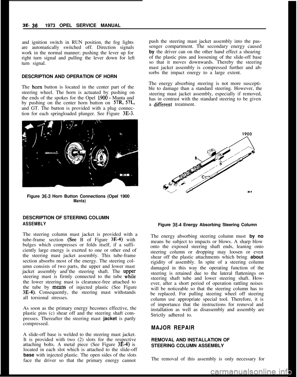
and GT. The button is provided with a plug connec-
tion for each springloaded plunger. See Figure
3E-3.Figure
3E-3 Horn Button Connections (Opel 1900Manta)DESCRIPTION OF STEERING COLUMN
ASSEMBLYThe steering column mast jacket is provided with a
tube-frame section
.(See B of Figure 3E-4) with
bulges which compresses or folds itself, if a suffi-
ciently large energy is exerted to one or other end of
the steering mast jacket assembly. This tube-frame
section absorbs most of the energy. The steering col-
umn consists of two parts, the upper and lower mast
jacket assembly and’the steering shaft. The
upp,ersteering mast is firmly connected to the tube while
the lower steering mast is clearance-free attached to
the tube by means of injected plastic (See Figure
3E-4). Consequently, the steering mast withstands
all torsional stresses.
As soon as the primary energy becomes effective, the
plastic pins (c) shear off and the steering shaft com-
presses. Thereafter the steering mast jacket is partly
compressed.
A slide-off base is welded to the steering mast jacket.
It is provided with two (2) slots for the respective
attaching bolts. A metal piece (See Figure 3E-4) is
located in each slot which is attached to the slide-off
base with injected plastic. The open sides of the slots
face the driver so that the primary energy cannotpush the steering mast jacket assembly into the pas-
senger compartment. The secondary energy caused
by the driver can on the other hand effect a shearing
of the plastic pins and loosening of the slide-off base
so that it moves downwards. Thereby the steering
mast jacket assembly is compressed further and ab-
sorbs the impact energy to a large extent.
The energy absorbing steering is not more suscepti-
ble to damage than a standard steering. However, the
steering mast jacket assembly, especially if removed,
has in contrast with the standard steering to be given
a difierent treatment.
Figure
3E-4 Energy Absorbing Steering Column
The energy absorbing steering column must by no
means be subject to impacts or blows. A sharp blow
onto the exposed steering shaft ends, leaning onto
steering column or dropping may loosen or even
shear off the plastic attachments which bring about
rigidity of assembly. In spite of a steering column
damaged in this way the operating function of the
steering is retained due to the lateral flattenings on
steering shaft tube and lower steering shaft. How-
ever, after a short period of operation rattling noises
will be noticeable so that the steering column has to
be replaced. For pulling steering wheel off steering
column use appropriate special tool. Therefore, it is
of importance that the instructions for removal and
installation as well as disassembly and assembly are
Strictly adhered to.
MAJOR REPAIRREMOVAL AND INSTALLATION OF
STEERING COLUMN ASSEMBLY
The removal of this assembly is only necessary for
Page 215 of 625
3E- 481973 OPEL SERVICE MANUAL
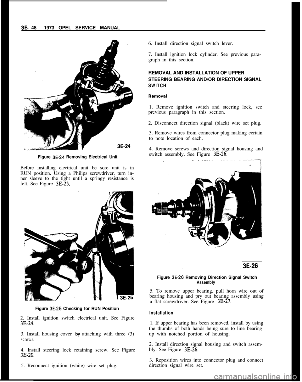
Figure 3E-24 Removing Electrical Unit
Before installing electrical unit be sore unit is in
RUN position. Using a Philips screwdriver, turn in-
ner sleeve to the tight until a springy resistance is
felt. See Figure 3E-25.Figure 3E-25 Checking for RUN Position
2. Install ignition switch electrical unit. See Figure
3E-24.3. Install housing cover by attaching with three (3)
screws.4. Install steering lock retaining screw. See Figure
3E-20.5. Reconnect ignition (white) wire set plug.6. Install direction signal switch lever.
7. Install ignition lock cylinder. See previous para-
graph in this section.
REMOVAL AND INSTALLATION OF UPPER
STEERING BEARING AND/OR DIRECTION SIGNAL
SWITCH1. Remove ignition switch and steering lock, see
previous paragraph in this section.
2. Disconnect direction signal (black) wire set plug.
3. Remove wires from connector plug making certain
to note location of each.
4. Remove screws and direction signal housing and
switch assembly. See Figure
3E-26.
..3E-26
Figure 3E-26 Removing Direction Signal Switch
Assembly5. To remove upper bearing, pull horn wire out of
bearing housing and pry out bearing assembly using
a flat screwdriver. See Figure
3E-27.
Installation1. If upper bearing has been removed, install by using
the thumbs of both hands being sure to line bearing
up with notched portion of housing.
2. Install direction signal housing and switch assem-
bly. See Figure 3B26.
3. Reposition wires into connector plug and connect
direction signal wire set.
Page 222 of 625
WHEELS AND TIRES3G- 55
WHEELS AND TIRES
CONTENTS
Subject
DESCRIPTION AND OPERATION: (Not Applicable)
DIAGNOSIS:
Car
RoughnessandVibration. . . . . . . . . . . . . . . . . . . . . . . . . . . . . . . . . . . . . . . .AbnormalTireWear
. . . . . . . . . . . . . . . . . . . . . . . . . . . . . . . . . . . . . . . . . . . . . . . . . . . . . . . . . .MAINTENANCE AND ADJUSTMENTS:
Demounting and Mounting Tubeless Tires
. . . . . . . . . . . . . .Wheel
andTireBalance. . . . . . . . . . . . . . . . . . . . . . . . . . . . . . . . . . . . . . . . . . . . . . . . . .MAJOR REPAIR: (Not Applicable)
SPECIFICATIONS:
Specifications
. . . . . . . . . . . . . . . . . . . . . . . . . . . . . . . . . . . . . . . . . . . . . . . . . . . . . . . . . . . . . . . . . . . . . .Page No.
3G-55
3G-58
3G-6136-6236-62
DIAGNOSIS
CAR ROUGHNESS AND VIBRATIONinflation pressures and perform tire inspection, in-
cluding removal of any foreign material on tire tread
or wheel large enough to upset balance.
Possible Causes
To assist in the diagnosis and correction of some of
the more stubborn cases of tire vibration and rough-
ness conditions that may be encountered, the follow-
ing information is offered:Tire inflation pressure recommendations are very
important at all times and particularly so on all ride
complaints. Raising or lowering tire pressures to
“improve” mileage or traction should not be at-
tempted.
VIBRATION, or a quivering motion condition, no-
ticeable by feel through the steering column, steering
wheel, floor
p&n, or by hood and fender shake, usu-
ally originates from the front wheels and tires. Front
end vibration, when caused by unbalanced front
wheels, can be generally felt as steering wheel “nib-ble”.Next, road-test the car with the owner, if possible,
and have the owner explain the specific ride disturb-
ance.After road-testing, raise car on hoist and proceed to
isolate the offending tire/wheel assembly.
Reproducing the Disturbance
A vibration felt through the seats as a side-to-side
disturbance can usually be attributed to the rearIn an attempt to reproduce the disturbance ex-
wheels and tires.perienced in the ride, a wheel spinner can be used on
the front wheels of the car.
Both front and rear vibration can be noticed mainly
at highway speeds, usually over 60 mph.The rear wheels may be spun by placing car in
“Drive” with engine running.
ROUGHNESS, noticeable primarily at speeds be-
tween 40 and 65 mph, can be felt (and occasionally
heard), and is due to certain irregularities in the tire.
Roughness usually sets up a “trembling” feel or a
shuddering effect.When spinning rear wheels, never exceed a speedom-
eter speed of 35 mph with a standard rear axle assem-
bly, or 75 mph on one with a positive traction rear
axle. Excessive speeds may cause damage to the rear
axle assembly.
Road-Test With Owner
When a ride complaint is encountered, first checkJack up both rear wheels by placing the jack under
the differential housing. Spin one wheel and tire with
the opposite wheel held from rotating by holding the
Page 225 of 625
3G- 581873 OPEL SERVICE MANUALTire Wear IrregularitiesAn additional cause of vibrations may sometimes be
tire wear irregularities. These can also produce noise
disturbances, and can be generally corrected by
rotating the tires, Figure
3G-6. Before proceeding
further, locate and correct the cause of the irregular
tire wear. See Figure
3G-7.Use the criss-cross method of rotation of tires only
when all four tires are equally worn. In some in-
stances, it may be necessary to put the truest running
assemblies (those with the lowest tolerances) on the
front of the car.
Wheel Nut Torque end Tightening SpecificationsDuring all wheel installations, it is important to use
the correct procedures for installing wheel nuts and
torquing them uniformly and in proper sequence.
This is important in order to avoid possible distor-
tion of the brake drum or disc, and to minimize
damage to lug and nut threads and wheel stud holes.
To assure uniform tightening of wheel lug nuts, the
following procedure is recommended:
1. Install wheel lug nuts in a criss-cross pattern and
tighten just enough to seat wheel against hub. This
assures proper piloting of the wheel on its hub.
2. Tighten lug nuts uniformly to proper torque of 65
Ib.ft. using criss-cross pattern.
An impact wrench should not be used, as uniform
torque control cannot be maintained.
Summary of Diagnosis end Correction of Tire and
Wheel Vibration1. Inflate all tires to recommended pressure and
road-test car with owner to define problem.
2. Spin front tire/wheel assemblies with wheel driv-
ing equipment. Rear wheels may be spun with tires
off the ground and with one wheel held at a time. The
offending tire may cause vibration that may be felt
by touching the bumper or fender. By process of
elimination, determine offending tire/wheel assem-
bly.
3. Check for tire/wheel unbalance. Balance, if neces-
sary.4. Check each tire/wheel assembly on the car for
radial runout on the tire tread. Wheel and tire assem-
blies exceeding
.050 inches may be considered as
offending assemblies. Offending tire/wheel assemblyshould be deflated and the tire repositioned (indexed)
180 degrees from original location.
5. After repositioning, rebalance tire/wheel assembly
(static and dynamic preferred).
6. Test drive and evaluate correction.
The following procedure should be used to determine
cause of roughness or vibration with car in operation
at various speeds:
I. Jack up all wheels having jack support rear end of
car at center of rear axle housing.
2. With transmission in “Drive”, run engine at vari-
ous car speeds to note speeds at which vibration or
roughness occurs.
3. Remove rear wheels and run engine again at the
critical speeds noted in step 2. If roughness is gone,
the condition is caused by unbalanced wheel and tire
assemblies.
4. If roughness still exists with rear wheels removed,
remove rear brake drums and repeat the running
test. Elimination of the roughness indicates out of
balance brake drums.
5. If roughness still exists with brake drums
removed, run engine with transmission in “Neutral”.
Elimination of the roughness indicates that propeller
shaft is out of balance. Continued roughness indi-
cates an out-of- balance engine.
ABNORMAL TIRE WEAR
General Operating ConditionsAssuming that there is no misalignment condition to
cause abnormal wear, the life of tires depends largely
upon car operation conditions and driving habits.
Tires wear at a much faster rate in some localities
than in others because of road and operating condi-
tions. Some types of roads are much more abrasive
than others. Tire wear is also dependent upon the
number of hills and mountains which the car must
go up and down, the severity of grades, the number
of starts and stops, driging speeds, the amount of rain
and snow, and prevailing temperatures. Tire
wear
increases rapidly with speed, temperature, and loadon tire. Tires used at low speeds, in cool climates, or
with light loads will have longer life than tires used
for high-speed driving in hot climates with heavy
loads.
Driving habits have a very important hearing on tire
life. A careful driver may obtain much greater mile-
age from a set of tires than would be obtained by a