wheel size OPEL GT-R 1973 Service Manual
[x] Cancel search | Manufacturer: OPEL, Model Year: 1973, Model line: GT-R, Model: OPEL GT-R 1973Pages: 625, PDF Size: 17.22 MB
Page 177 of 625

3A- 101973 OPEL SERVICE MANUAL
Figure 3A-18 Lower Ball Joint Notch Opel 1900 -
MantaUPPER CONTROL ARM REMOVAL AND
INSTALLATION
Removal GT1. Raise car and support at rear of front frame rails.
2. Remove front wheel.
3. Install spring compressor and compress spring
until there is 3-l/8” between compressor and lower
spring leaf.
4. Remove cotter pin and castle nut from upper ball
joint stud. Discard cotter pin.
5. Use tie rod remover J-21687 remove ball jointfrom.steering knuckle. 6. Support brake drum to
relieve tension on brake hose.
7. Remove hex nut from upper control arm shaft.
Remove shaft and washers from shock absorber sup
port. Do not damage threads on control arm shaft.
8. Remove control arm from car. Do not lose inner
toothed washers. Note size and location of toothed
washers.Removal
Opel 1900 . Manta
1, Raise car and support at rear of front frame rails.
2. Remove front wheel
3. Unscrew upper control arm to cross member
self-locking attaching nut.4. Unscrew ball joint from upper control arm. Do not
turn upper control arm ball joint flange, as this
would result in a change of camber.
5. Support front wheel hub so that brake hose is not
stressed.6. Pull out upper control shaft to cross member at-
taching bolt and remove control arm. Shims have to
be reinstalled in their original location to maintain
the proper caster setting.
Installation GT
CAUTION:
Fasteners are important attaching parts in
that they could affect the the
perfonmmce of vital
components and systems, and/or could result in ma-
jor repair expense. They must be replaced with one
of the same part number or with an equivalent part
if replacement becomes necessary. Do not use a re-
placement part or lesser quality or substitute design.
Torque values must be used as specified during reas-
sembly to
assure proper retention of these parts.If rubber bushings on control arms are worn, arms
must be replaced.
1. Slide rubber rings over bushings. Slide rings over
inner sleeves of bushings. Place control arm in posi-
tion on shock absorber support, installing toothed
washers in their original positions. See Figure 3A-
19.2. From front to rear, install control arm shaft. If
necessary, align washers and control arm bushings
with a small drift prior to installing control arm
shaft. See Figure
3A-19.3. Tighten hex nut on control arm shaft finger tight.
4. Increase tension on spring compressor in order to
relieve tension on control arm shaft. Then torque hex
nut on control arm shaft to 33
Ib.ft.5. Press ball joint stud into steering knuckle and
torque castle nut to 29 lb.ft. Install new cotter pin.
6. Remove spring compressor and lower car.
7. Check front end alignment.
Installation Opel 1900. Manta
CAUTION:
Fasteners are important attaching parts in
that they could at?&
the performance of vital com-
ponents and systems, and/or
coo/d result in major
repair expense. They must be replaced with one of
the same part number or with equivalent parts, if
replacement becomes necessary. Do not use a
re-
Page 229 of 625

3G- 621973 OPEL SERVICE MANUAL
1. Clean rims thoroughly, using No. 3 coarse steel
wool to remove all oxidized rubber, soap solution,
etc. Remove rust with wire brush.2. Inspect butt weld and other areas of rim contactedby tire beads to make certain there is no groove or
high spot. Remove any groove or high spot by tiling
smooth.
3. Inspect valve stem and replace it if damaged.
Make certain that valve stem is properly installed to
provide an air tight joint.
4. Before mounting a tubeless tire on a wheel, mois-
ten a cloth with mounting compound or soap solu-
tion and wipe rim-seal ridges of both beads to remove
all foreign substances.
5. Moisten base of both beads with mounting com-
pound or soap solution to help beads snap into place
when tire is inflated. Start tire over rim flange at
point opposite valve stem.
6. Inflate tire until both beads are firmly seated
against rim flanges and temporarily over inflate.
Leak test wheel and tire assembly and if satisfactory,
reduce to recommended pressure.
SPECIFICATIONSWHEEL AND TIRE BALANCE
Wheel and tire balance is the equal distribution of the
weight of the wheel and tire assembly around the axis
of rotation. Wheel unbalance is the principal cause of
tramp and general car shake and roughness and con-
tributes somewhat to steering troubles.
The original balance of the tire and wheel assembly
may change as the tire wears. Severe acceleration,
severe brake applications, fast cornering and side slip
wear the tires out in spots and often upset the origi-
nal balance condition and make it desirable to rebal-
ance the tire and wheel as an assembly. Tire and
wheel assemblies should be rebalanced after punc-
tures are repaired.
Because of the speed at which cars are driven, it is
necessary to test the wheel and tire assembly for
dynamic balance. Dynamic balancing of a wheel and
tire assembly must be done on a machine designed to
indicate out-of-balance conditions while the wheel is
rotating on the car. Since procedures differ with dif-
ferent machines, the instructions of the equipment
manufacturer must be carefully followed.
General SpecificationsWheels
Opel 1900
- Manta and GT ,._......,,,._.................,...,,..............................~,,,.................... 5.J x 13
Tires
1900 - Manta __.......,,___.,...,,..,.....,,....,,...........,...,,.,,...,.........,,..................,....................... 165-13
GT . . . . . . . ..__........_..............,...,,........,,,...,,..........,....,..,,...,,........,..................,,,.....................165-13
Tire Size and Pressures (Pounds Per Square Inch
Cold)
ModelTire Size51.53.54.57
165-1357R.57L165-13
77
165-13Recommended(Standard
PressureInflation)
FrontRear24
PSI32PSI23
PSI26PSI
19PSI23
PSI
NOTE:
1.Tire inflation pressures may increase as much as 6 pounds per square inch
when hot.
2.For continuous high-speed operation (over 75 MPH), increase tire inflation
pressures 4 pounds per square inch over the recommended pressures up to a
maximum of 30 pounds per square inch cool for 4 ply rating tires. When the
4 psi pressure adjustment for sustained high speed with maximum vehicle load
Page 290 of 625
DRUM BRAKES5c- 31
remove grooves, and the ridges in the lining should
be lightly removed with a lining grinder.
If brake linings are more than half worn, but do not
need replacement, the drum should be polished with
fine emery cloth but should not be rebored. At this
stage, eliminating the grooves in drum and smooth-
ing the ridges on lining would necessitate removal of
too much metal and lining, while if left alone, the
grooves and ridges match and satisfactory service
can be obtained.
If brake linings are to be replaced, a grooved drum
should be rebored for use with oversize linings. A
grooved drum, if used with new lining, will not only
wear the lining but will make it
diff%xlt, if not im-
possible, to obtain etXcient brake performance.
Out-of-Round DrumAn out-of-round drum makes accurate brake shoe
adjustment impossible and is likely to cause excessive
wear of other parts of brake mechanism due to its
eccentric action. An out-of-round drum can also
cause brake pulsation. Maximum permissible drumrunout is 004”. A drum that has more run-out than
this should be rebored. Runout can be accurately
checked by using an inside micrometer fitted with
proper extension rods.
When measuring a drum for run-out, take measure-
ments at open and closed edges of machined surface
and at right angles to each other.
Turning Brake DrumsIf a brake drum is to be turned, enough metal should
be removed to obtain a true, smooth braking surface.
Measure brake drum diameter; standard drum inner
diameter is 9.060”. Drums may be turned to an over-
size of ,030”. If maximum inner diameter after turn-
ing exceeds 9.090”, brake drum will have to be
replaced. Removal of more metal will affect dissipa-
tion of heat and may cause distortion of the drum.
1. Remove rear wheels and drums.
2. Mount brake drum on brake drum lathe and turn
drums as necessary, within limits.
3. After turning, check drum diameter. Inner diame-
ter not to exceed 9.090.
4. A newly-bored drum should always have center
contact with brake shoes. For this reason, arc grind
linings to
.OlO” under drum radius, or to ,020” under
drum diameter.
5. Clean and install drums and wheels.
BRAKE WHEEL CYLINDER OVERHAUL1. Remove wheel, drum, and brake shoes. Be careful
not to get grease or dirt on brake lining.
2. Disconnect brake pipe or hose from wheel cylinder
and cover opening with tape to prevent entrance of
dirt. Remove wheel cylinder from backing plate.
3. Remove boots, pistons, cups, and spring from cyl-
inder. Remove bleeder valve.
4. Discard rubber boots and piston cups. Thoroughly
clean all other parts with hydraulic brake fluid orDeclene. Do not use anti-freeze, alcohol, gasoline,
kerosene, or any other cleaning fluid that might con-
tain even a trace of mineral oil.
5. Inspect pistons and cylinder bore for scores, scrat-
ches, or corrosion. Light scratches may be polished
with crocus cloth. Do not use emery cloth or sandpa-
per.
Shght corro~on may be cleaned wth tine steel
wool. If scratches or corroded spots are too deep to
be polished satisfactorily, the cylinder should be re-
placed since honing is not recommended.
6. Dip internal parts in brake fluid and reassembly
wheel cylinder. When installing piston cups, use care
to avoid damaging the edges.
7. If the rear wheel backing plate is removed: Always
install new paper gaskets one on each side
- on the
backing plate. Prior to installation, lightly coat paper
gaskets with chassis lubricant. Torque backing plate
to rear axle housing bolts to 43
lb.ft. and wheel brake
cylinder to backing plate bolts to 5
lb.ft. Install wheel
cylinder on brake backing plate and connect brake
pipe or hose.
8. Install brake shoes, drum, and wheel, then flush
and bleed hydraulic system.
9. Adjust brakes, then road test car for brake per-
formance.
CAUTION:This brake backing plate to rear axle fis-
tener is an important attaching part in that it could
affect the performance of vital components and sys-
tems, and/or could result in major repair expense. It
must be replaced with one of the same part number
or with an equivalent part, if replacement becomes
necessary. Do not
use a replacement part of lesser
quahty or substitute design. Torque v&es must be
used as specified during reassembly to assure proper
retention of this part.
REPLACING BRAKE PIPESAny brake pipe assembly which is needed must be
made up from service bulk tubing and fittings. All
brake pipes must be made of tin or copper coated
wrapped steel tubing with the ends double lap flared.
Page 291 of 625
5C- 321973 OPEL SERVICE MANUAL
Never use copper tubing because copper is subject to
fatigue cracking which would result in brake failure.2. Cut tubing to length. The correct length may be
determined by measuring the old pipe using a cord
and adding l/8” for each double lap flare.
To make up a brake pipe assembly, proceed as fol-
lows:3. Double lap flare tubing ends, using a suitable flar-
ing tool such as J-8051. Follow the instructions in-
cluded in the tool set. Make sure fittings are installed
1. Procure the recommended tubing and fittings of
the correct size. (Outside diameter of tubing is used
to specify size.)before starting second flare.
4. Bend pipe assembly to match old pipe.
SPECIFICATIONS
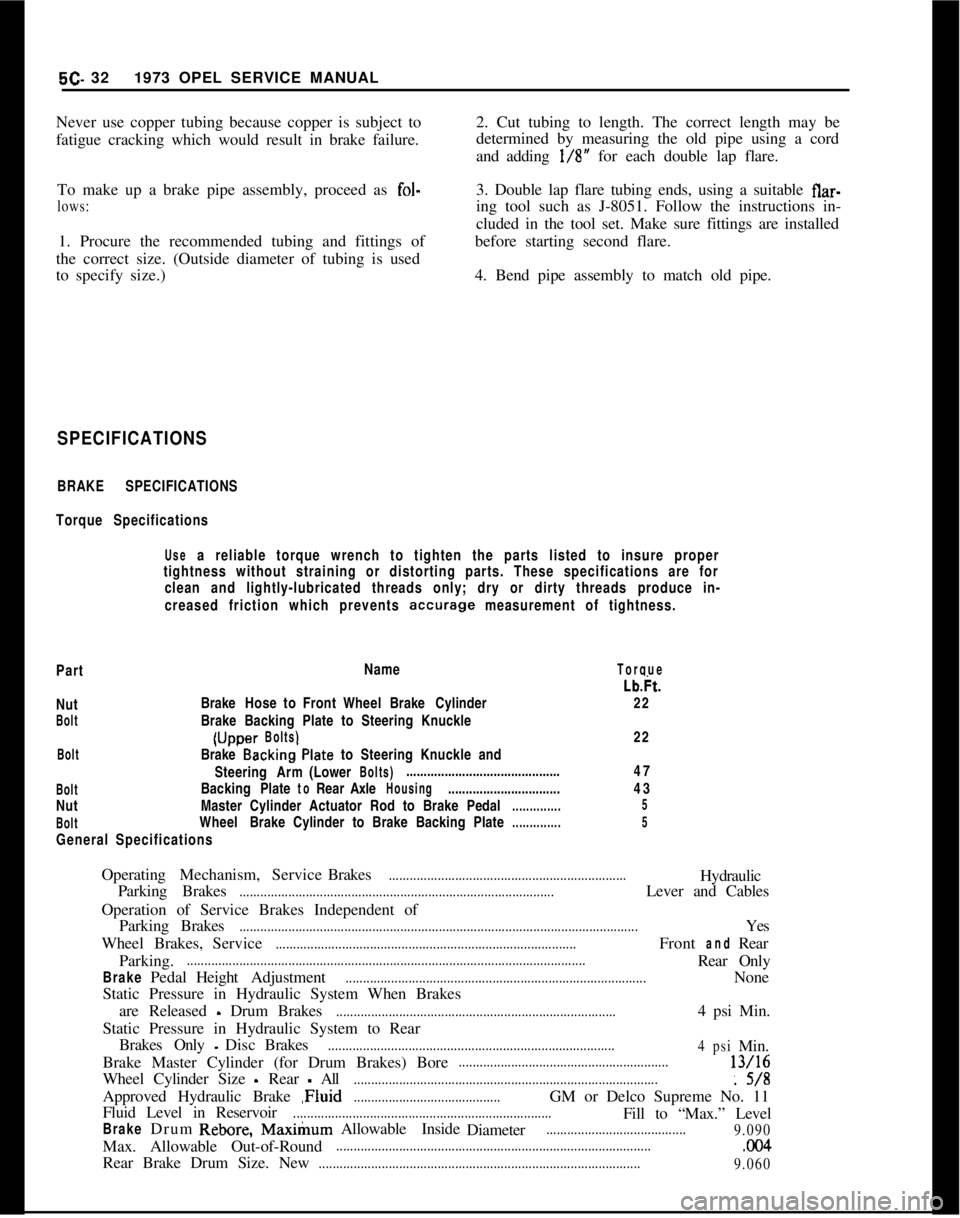
BRAKE SPECIFICATIONS
Torque Specifications
Use a reliable torque wrench to tighten the parts listed to insure proper
tightness without straining or distorting parts. These specifications are for
clean and lightly-lubricated threads only; dry or dirty threads produce in-
creased friction which prevents
accurage measurement of tightness.
PartName
TorqueNut
BoltBrakeHose to Front WheelBrake Cylinder
Brake Backing Plate to Steering Knuckle(Uccer
Bolts)Lb&.
22
22...BoltBrake Backing’Plate to Steering Knuckle and
SteeringArm(Lower
Bolts)............................................
BoltBackingPlatetoRearAxleHousing................................
NutMaster Cylinder Actuator Rod to BrakePedal
..............
BoltWheelBrake Cylinder to Brake Backing Plate
..............
General Specifications47
43
5
5OperatingMechanism,ServiceBrakes
....................................................................Hydraulic
Parking Brakes
..........................................................................................Lever and Cables
Operation of Service Brakes Independent of
ParkingBrakes
..................................................................................................................Yes
WheelBrakes,Service
......................................................................................FrontandRear
Parking.
..................................................................................................................Rear Only
BrakePedalHeightAdjustment......................................................................................None
Static Pressure in Hydraulic System When Brakes
are Released
- Drum Brakes................................................................................4 psi Min.
Static Pressure in Hydraulic System to Rear
BrakesOnly
-DiscBrakes..................................................................................
4psiMin.
Brake Master Cylinder (for Drum Brakes) Bore
............................................................13/16
Wheel Cylinder Size
- Rear - All.......................................................................................: 5/8
Approved Hydraulic Brake ,Fluid
..........................................GM or Delco Supreme No. 11
Fluid Level in Reservoir
..........................................................................Fill to “Max.” Level
BrakeDrumRebore,Max&urnAllowable Inside
Diameter........................................
9.090Max. Allowable Out-of-Round
...........................................................................................CKl4Rear Brake Drum Size. New
............................................................................................
9.060
Page 309 of 625
6A- 18 1973 OPEL SERVICE MANUAL
pressure. If heavy pressure is required, shell was not
started squarely and will be distorted if force into place.
12. Place lower bearing shell in bearing cap, then
check clearance
with plastic-type gauge, as previ-
ously described.
13. The desired clearance with a new bearing is
.0009” to .0025”. If this clearance cannot be obtained
with a standard size bearing, insert an undersize
bearing and check again
w&h plastic-type gauge
material.
14. When the proper size bearing has been selected,
clean out all plastic gauge material, oil the lower
shell and reinstall bearing cap. Clean the bolt holes
and lube bolts, then torque cap bolts to 72 lb. ft. The
crankshaft should turn freely at flywheel rim; how-
ever, a very slight drag is permissible if an undersize
bearing is used.
15. If the thrust bearing shell is disturbed or replaced
it is necessary to line up the thrust surfaces of the
bearing shell before the cap bolts are tightened. To
do this, move the crankshaft fore and aft the limit of
its travel several times (last movement fore) with the
thrust bearing cap bolts finger tight.
16. After bearing is installed and tested, loosen all
bearing cap bolts
l/2 turn and continue with other
bearings. When bearings have been installed and
tested, tighten all bearing cap bolts to 72 lb. ft.
17. Replace rear bearing oil seals.
18. Install pipe and screen assembly and oil pan.
Installation of Rear Bearing Oil
Seals (Engine in Vehicle)
1. Remove transmission, bell housing and clutch.
Refer to appropriate section for removal procedures.
Figure 6A-28 Removing Rear Main Oil Seal
2. Remove flywheel.
3. Punch a hole into oil seal and screw in a sheet
metal screw and pull out oil seal. See Figure
6A-28.
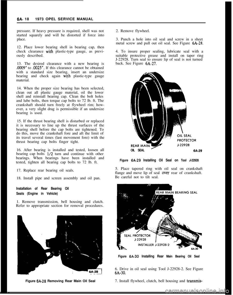
4. To insure proper sealing, lubricate seal with a
suitable protective grease and install on taper ring
J-22928. Turn seal to ensure lip of seal is not turned
back. See Figure
6A-27.
OIL SEAL’6A-29
Figure
6A-29 Installing Oil Seal on Tool J-22928
5. Place tapered ring with oil seal on crankshaft
flange and move lip of seal
over rear of crankshaft.
Be careful not to tilt seal.
Figure 6A-30 Installing Rear Main Bearing Oil Seal
6. Drive in oil seal using Tool J-22928-2. See Figure
6A-30.
7. Install flywheel, clutch, bell housing and transmis-
.
Page 310 of 625
ENGINE MECHANICAL AND MOUNTS6A- 19
sion. When replacing flywheel use new bolts and
torque to 43 lb.ft.
PISTON, RINGS AND CONNECTING RODS
Removal and Disassembly of Piston
and Rod Assemblies
1. Drain oil.
2. Remove oil pan. 3. Remove cylinder head.
4. Examine the cylinder bores above the ring travel.
If bores are worn so a ridge exists, remove the ridges
with a ridge reamer to avoid damaging rings or
cracking ring lands in pistons during removal.
5. Mark the cylinder number on all pistons, connect-
ing rods and caps. Starting at the front end of the
crankcase, the cylinders are numbered l-2-3-4,
6. Remove cap and bearing shell from number 1
connecting rod.
7. Push the piston and
rod assembly up and out of
top cylinder. Then reinstall cap and bearing shell on
rod.
0
-J-23436-4
J-23436-2+
J-6047
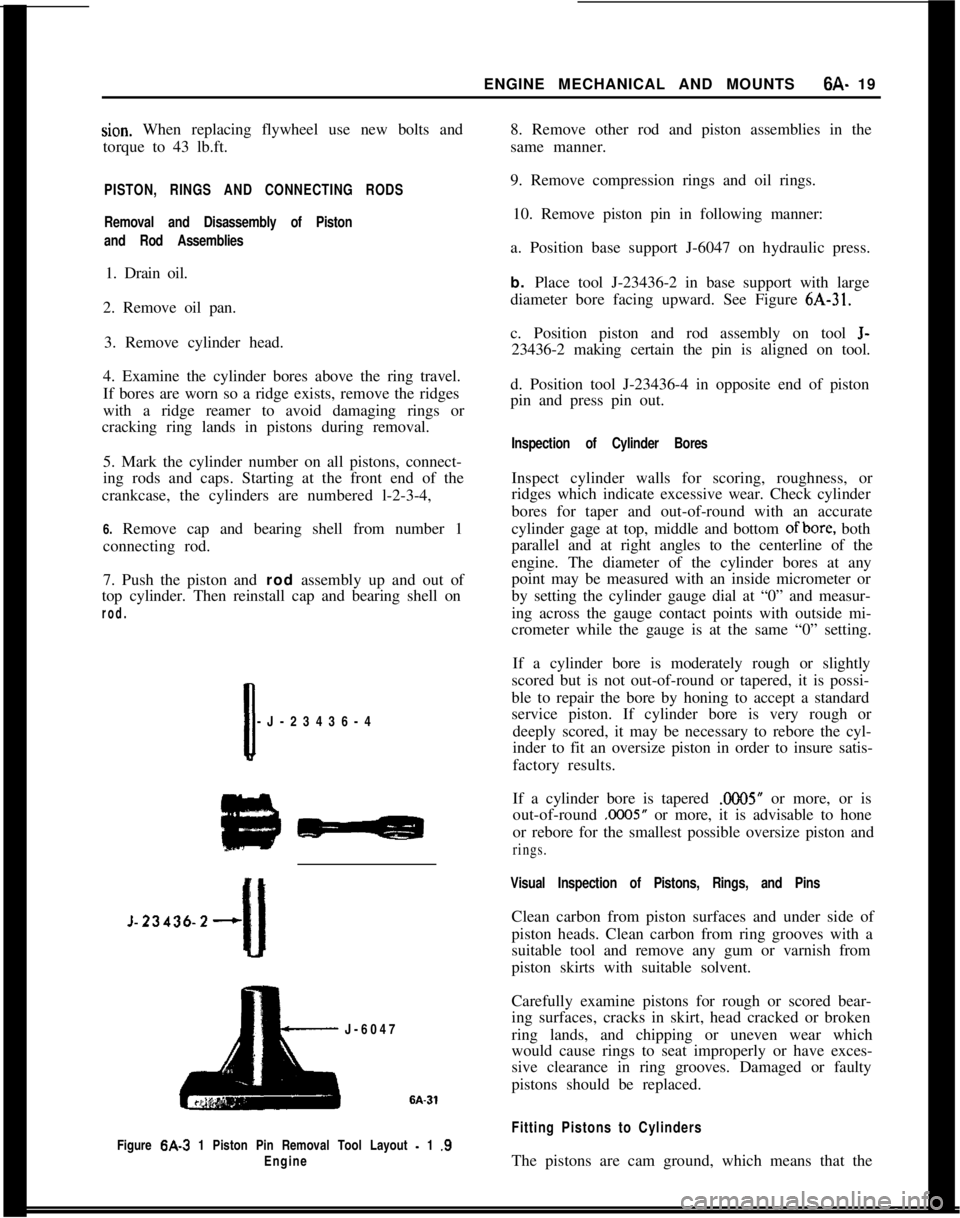
Figure
6A-3 1 Piston Pin Removal Tool Layout - 1 .S
Engine
8. Remove other rod and piston assemblies in the
same manner.
9. Remove compression rings and oil rings.
10. Remove piston pin in following manner:
a. Position base support J-6047 on hydraulic press.
b. Place tool J-23436-2 in base support with large
diameter bore facing upward. See Figure
6A-31.
c. Position piston and rod assembly on tool
J-
23436-2 making certain the pin is aligned on tool.
d. Position tool J-23436-4 in opposite end of piston
pin and press pin out.
Inspection of Cylinder Bores
Inspect cylinder walls for scoring, roughness, or
ridges which indicate excessive wear. Check cylinder
bores for taper and out-of-round with an accurate
cylinder gage at top, middle and bottom
ofbore, both
parallel and at right angles to the centerline of the
engine. The diameter of the cylinder bores at any
point may be measured with an inside micrometer or
by setting the cylinder gauge dial at “0” and measur-
ing across the gauge contact points with outside mi-
crometer while the gauge is at the same “0” setting.
If a cylinder bore is moderately rough or slightly
scored but is not out-of-round or tapered, it is possi-
ble to repair the bore by honing to accept a standard
service piston. If cylinder bore is very rough or deeply scored, it may be necessary to rebore the cyl-
inder to fit an oversize piston in order to insure satis-
factory results.
If a cylinder bore is tapered
.ooO5” or more, or is
out-of-round
.0005” or more, it is advisable to hone
or rebore for the smallest possible oversize piston and
rings.
Visual Inspection of Pistons, Rings, and Pins
Clean carbon from piston surfaces and under side of
piston heads. Clean carbon from ring grooves with a
suitable tool and remove any gum or varnish from
piston skirts with suitable solvent.
Carefully examine pistons for rough or scored bear-
ing surfaces, cracks in skirt, head cracked or broken
ring lands, and chipping or uneven wear which
would cause rings to seat improperly or have exces-
sive clearance in ring grooves. Damaged or faulty
pistons should be replaced.
Fitting Pistons to Cylinders
The pistons are cam ground, which means that the
Page 497 of 625
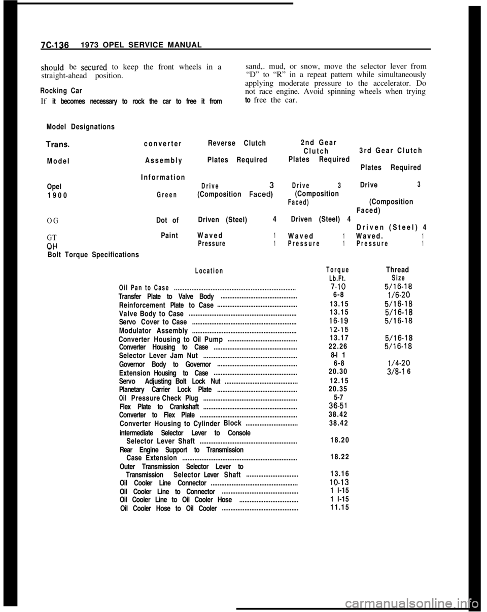
7C-1361973 OPEL SERVICE MANUALshould be secured to keep the front wheels in a
straight-ahead position.sand,. mud, or snow, move the selector lever from
“D” to “R” in a repeat pattern while simultaneously
applying moderate pressure to the accelerator. DoRocking Carnot race engine. Avoid spinning wheels when trying
If it becomes necessary to rock the car to free it fromto free the car.
Model DesignationsTrans.
converterReverse Clutch
ModelAssemblyPlates Required2nd Gear
Clutch3rd Gear Clutch
Plates Required
Plates RequiredOpel
1900
OG
GT
CIHInformation
Drive
(Composition Faced:
Drive3Drive3
Green
(Composition
Faced)(CompositionFaced)
Dot ofDriven (Steel)4Driven (Steel) 4
Driven (Steel) 4
PaintWaved1Waved1Waved.1Pressure1Pressure1Pressure1-.
Bolt Torque Specifications
Location
Oil Pan to Case......................................................................Transfer Plate to Valve Body............................................
ReinforcementPlatetoCase..............................................
ValveBodytoCase..............................................................
ServoCovertoCase............................................................
Modulator Assembly............................................................
ConverterHousingtoOilPump........................................
Converter Housing to Case................................................
Selector Lever Jam Nut......................................................
Governor Body to Governor..............................................
ExtensionHousing to Case................................................
Servo AdjustingBolt Lock Nut..........................................
Planetary Carrier Lock Plate..............................................
OilPressureCheckPlug......................................................
Flex Plate to Crankshaft......................................................
Converter to Flex Plate........................................................
ConverterHousingtoCylinderBlock..............................
intermediate Selector Lever to Console
Selector Lever Shaft........................................................
Rear Engine Support to Transmission
CaseExtension..................................................................
Outer Transmission Selector Lever to
TransmissionSelectorLeverShaft..............................
Oil Cooler Line Connector..................................................
Oil Cooler Line to Connector............................................
Oil Cooler Line to Oil Cooler Hose..................................
Oil Cooler Hose to Oil Cooler............................................
Torque
Lb.Ft.7-10
6-8
13.15
13.1516-1812.15
13.17
22.26
8-l 1
6-8
20.30
12.15
20.35
5-736.5
138.42
38.42
Thread
Size
5/16-18
l/6-20
5/16-18
5/16-18
5/16-18
5/16-18
5/16-18
l/4-20
3/8-l 6
18.20
18.22
13.1610-13
1 l-15
1 l-15
11.15
Page 624 of 625
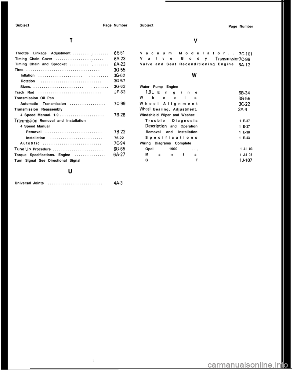
SubjectPage Number1
Throttle Linkage Adjustment........,:.......6E-51
Timing Chain Cover.......................6A-23
Timing Chain and Sprocket.........
':.......6A-23
Tires...................................36-55
Inflation.....................
.;.......3G-62
Rotation.............................36-57
Sizes.........................
........3G-62
Track Rod..............................3F-53
Transmission Oil Pan
Automatic Transmission.................7C-99
Transmission Reassembly
4 Speed Manual. 1.9.....................76-28Tranmission Removal and Installation
4 Speed Manual
Removal...........................7B-22
Installation.........................76-22
Auto&tic............................7c-94Tune’Up Procedure........................66-65
Torque Specifications. Engine...............6A-27
Turn Signal See Directional Signal
Universal Joints..........................4A-3Subject
VPage Number
Vacuum Modulator..7C-101
Valve Body Transmlssmn7C.99
Valve and Seat Reconditioning Engine6A-12
WWater Pump Engine1.9L Engine
Wheels
Wheel Alignment
Whee! Bearing, Adjustment,
Windshield Wiper and Washer:
Trouble Diagnosis:Description and Operation
Removal and Installation
Specifications
Wiring Diagrams Complete
Opel 1900 ._.
Manta
GT
1 E-37
1 E-37
1 E-38
1 E-43
1 J-l 03
1 J-l 05lJ-10768-3436-553C-223A-4