spark plugs replace OPEL GT-R 1973 Service Manual
[x] Cancel search | Manufacturer: OPEL, Model Year: 1973, Model line: GT-R, Model: OPEL GT-R 1973Pages: 625, PDF Size: 17.22 MB
Page 20 of 625
LUBRICATION AND MAINTENANCE OC-11
Throttle Linkage
Check for damaged or missing parts, interference or
binding. Any deficiencies should be corrected with-
out delay.
Headlights
Check for proper aim. Correct as necessary. More
frequent checks should be made if oncoming motor-
ists signal when you are already using your low
beams, or if illumination of the area ‘ahead seems
inadequate.
Underbody
In geographic areas using a heavy concentration of
road salt or other corrosive materials for snow re-
moval or road dust control, flush and inspect the
complete under side of the car at least once each
year, preferably after a winter’s exposure. Particular
attention should be given to cleaning out underbody
members where dirt and other foreign materials may
have collected.
EMISSION CONTROL MAINTENANCE
Thermostatically Controlled Air Cleaner
Inspect installation to make certain that all hoses and
ducts are connected and correctly installed. Also,
check valve for proper operation.
Carburetor Choke
Check choke mechanism for free operation. A bind-
ing condition may have developed from petroleum
gum formation on the choke shaft or from overtight-
ening of air cleaner clamp. Also check electric choke
terminal connections and fuse.
Timing, Dwell and Distributor
Adjust timing and dwell accurately as outlined under
Tune-Up in Group 6 at the first 4 months or 6,ooOmiles of operation, then at 12 month or
12,OQO mile
intervals. Adjustments must be made with test equip-
ment known to be accurate.
Replace distributor points every 12 months or 12,000
miles and carefully clean and inspect the complete
distributor cap to prevent misfiring and deteriora-
tion.
Carburetor and Idle
SpeedTorque carburetor attaching bolts and/or nuts to 12
ft.lbs. to compensate for compression of gasket atiirst 4 months or 6,000 miles of vehicle operation.Adjust idle speed to specifications with known accu-
rate equipment.
Proper functioning of the carburetor is particularly
essential to control of emissions. Correct mixtures
for emission compliance and idle quality have been
preset by Opel. Plastic idle mixture limiters have
been installed on the idle mixture screw, idle air
screw, and throttle stop screw to preclude unauthor-
ized adjustment. The plastic caps on the idle mixture
screw and the idle adjustment screw must be
removed to perform an idle speed adjustment. The
plastic cap on the throttle stop screw is not to be
removed unless some major carburetor repair or re-
placement which affects the throttle stop screw ad-
justment has been necessary.
Carburetor Fuel Inlet Filter
Replace filter at 12 month or
12,OCO mile intervals
or more often if clogged.
Spark Plugs
Replace at
6,ooO mile intervals when operating with
leaded fuels or at 12,000 mile intervals when using
unleaded fuels. Use of leaded fuels results in lead
deposits on spark plugs and can cause misfiring at
mileages less than
12,OilO miles. Where misfiring oc-
curs prior to
6,ooO miles, spark plugs in good condi-
tion can often be cleaned, tested and reinstalled in an
engine with acceptable results.
Spark Plug Wires
Inspect spark plug wires for evidence of checking or
cracking of exterior insulation and tight fit in the
distributor cap and at the spark plugs. Exterior of
wires should be cleaned, any evidence of corrosion
on ends removed and wire replace if deteriorated.
Positive Crankcase Ventilation System
The PCV metered orifice should be cleaned at 12,000
mile intervals under normal use, and at 6,000 mile
intervals when the vehicle is used under the follow-
ing conditions: driving in dusty conditions, extensive
idling, trailer pulling and short trip operation at
freezing temperatures (engine not thoroughly
warmed-up).
Evaporation Control System
Check all fuel and vapor lines and hoses for proper
connections and correct routing as well as condition.
Remove canister and check for cracks or damage.
Replace damaged or deteriorated parts as necessary.
Replace filter in open end of canister at 24month/24,000 mile intervals.
Page 39 of 625
1 C- 18 1973 OPEL SERVICE MANUAL
IGNITIPN SYSTEM
CbNTENTS
Subject
DESCRIPTION AND OPERATION: Ignition System ..................................................................
Ignition
Switc,h....................................................................
Ignition Coil
..........................................................................\
Distributor
............................I...............................................
DIAGNOSIS: (Not Available)
MAINTENANCE AND ADJUSTMENTS: Contact PointReplacement ............................................
Dwell Angle Adjustment :
................................................
Ignition Timing Adjustment ..........................................
Ignition Wire Inspection :
..................................................
Check Ignition Output ......................................................
Check Distributor
..............................................................
Check Spark Plugs
............................................................
MAJOR REPAIR: Distributor Removal ..........................................................
Disassembly ........................
I...............................................
Reassembly
..........................I...............................................
Distributor Installation
....................................................
SPECIFICATIONS: /
Ignition
Coil ..........................................................................
Distributor
....‘........................i...............................................
Spark Plugs ........................................................................\
..
DESCRIPTION AND OPERATION
INGITION SYSTEM
The ignition system basically consists of an ignitipn
switch, ignition coil, distributor, battery and related
wiring. The ignition switch is located in the steering
column, the ignition coil is located left front inner fender
skirt and the distributor is located at the left
front of the engine.
IGNITION SWITCH
The combined ignition switch and steering lock ian
be switched to any one of the below listed positions.
Insert key with notch pointing upward.
Page No.
lC-18
lC-18
lC-19
lC-19
1 c-20
1 c-20
1 c-20
lC-21 r
lC-21
1 c-22
1 c-22
1 r-23
1 C-23
1 c-24
1 C-25
1 C-26
1 C-26
1 C-26
(Fully counterclockwise) Lock position. Ignition
locked, steering locked, only with key removed.
Electrical circuits disconnected except to main light-
ing switch and dome lamp. The
key can be removed.
0- (First position clockwise from lock) Garage posi-
tion. ‘The key and lock assembly must be pushed “in”
to reach this position from lock. The steering is un-
locked and the ignition is off. The electrical circuits
are the same as in lock position. The key cannot be withdrawn.
l- [Chposition.) All electrical circuits controlled by
ignition switch are completed through the switch.
The key cannot
be removed while switch is in drive
position.
Page 42 of 625
IGNITION SYSTEMlC-214. Rota&distributor counterclockwise slightly until
contact pbints just start to open. This must be done
very carefully or engine will not start.
5. Install distributor cap. Make sure spark plug wires
are correctly installed in distributor cap, through clip
and on spark plugs.
Finish TimingIContact boint gap
(.016” at widest gap) or dwell 50
degrees plus or minus 3 degrees should always be
checked before adjusting ignition timing.
1. Connekt timing light to No. 1 spark plug.
2. Disconnect and plug vacuum advance unit and
retard u$it hoses.
3. Connect a tachometer from distributor side of coil
to
groun$l.4. Start dngine. Set idle speed to 900 RPM.
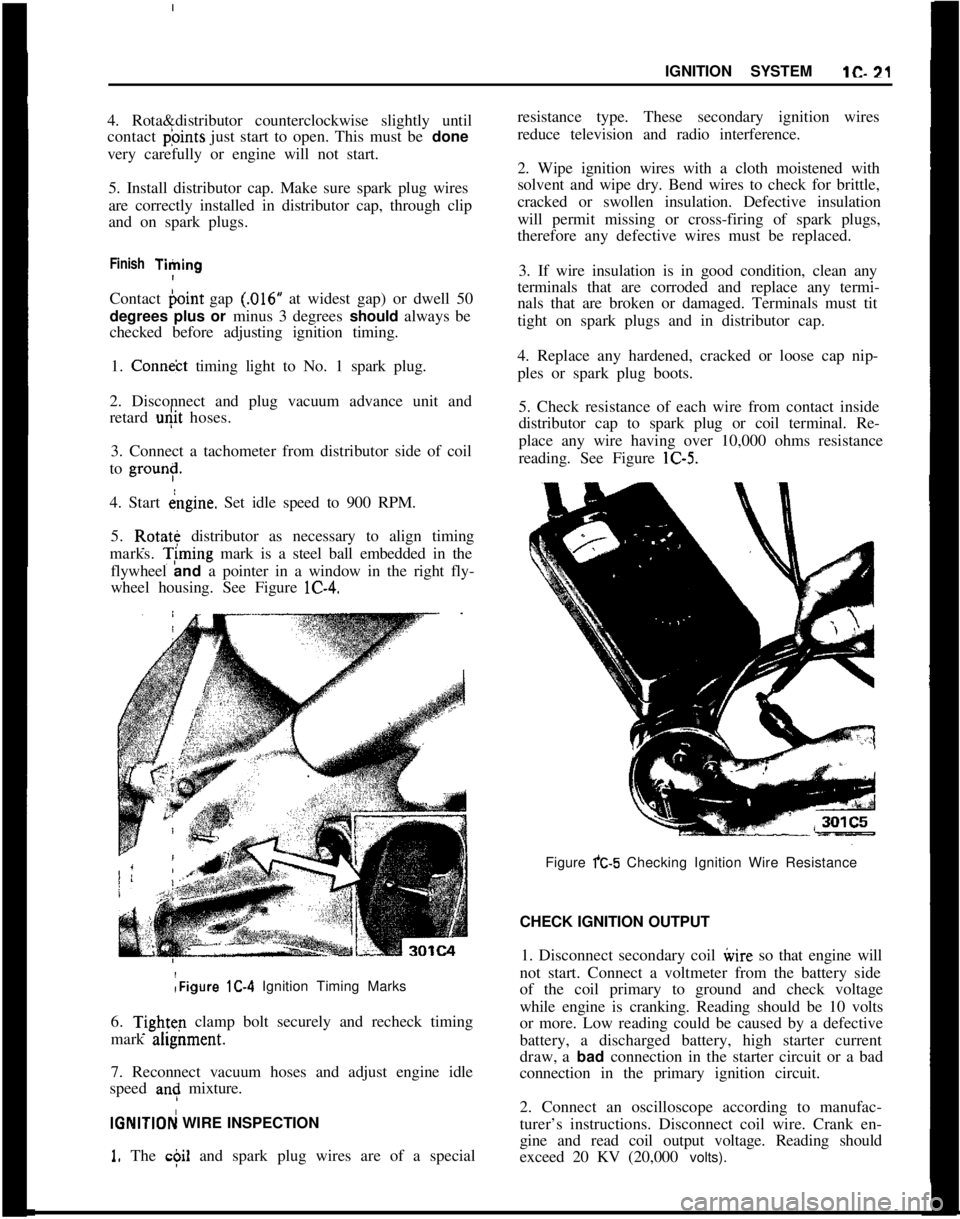
5. Rotate distributor as necessary to align timing
marks. T;ming mark is a steel ball embedded in the
flywheel and a pointer in a window in the right fly-
wheel housing. See Figure lC-4.:Figure lC-4 Ignition Timing Marks
6.
Tightq clamp bolt securely and recheck timing
mark ahgnment.
7. Reconnect vacuum hoses and adjust engine idle
speed
an: mixture.
IGNlTlOFj WIRE INSPECTION
1. The c$il and spark plug wires are of a specialresistance type. These secondary ignition wires
reduce television and radio interference.
2. Wipe ignition wires with a cloth moistened with
solvent and wipe dry. Bend wires to check for brittle,
cracked or swollen insulation. Defective insulation
will permit missing or cross-firing of spark plugs,
therefore any defective wires must be replaced.
3. If wire insulation is in good condition, clean any
terminals that are corroded and replace any termi-
nals that are broken or damaged. Terminals must tit
tight on spark plugs and in distributor cap.
4. Replace any hardened, cracked or loose cap nip-
ples or spark plug boots.
5. Check resistance of each wire from contact inside
distributor cap to spark plug or coil terminal. Re-
place any wire having over 10,000 ohms resistance
reading. See Figure lC-5.
Figure fC-5 Checking Ignition Wire Resistance
CHECK IGNITION OUTPUT
1. Disconnect secondary coil ivire so that engine will
not start. Connect a voltmeter from the battery side
of the coil primary to ground and check voltage
while engine is cranking. Reading should be 10 volts
or more. Low reading could be caused by a defective
battery, a discharged battery, high starter current
draw, a bad connection in the starter circuit or a bad
connection in the primary ignition circuit.
2. Connect an oscilloscope according to manufac-
turer’s instructions. Disconnect coil wire. Crank en-
gine and read coil output voltage. Reading should
exceed 20 KV (20,000 volts).
Page 43 of 625
lC- 22 1973 OPEL SERVICE MANUAL j
3. Start engine and disconnect a wire from a spark
plug. Read output voltage of disconnected spark
plug circuit. Reading should exceed 20 KV
(20,poO
volts).I
CHECK DISTRIBUTOR
!1. Clean distributor cap and inspect it for cracks or
tracking. Inspect inner segments for erosion and
outer sockets for corrosion.
2. Clean and inspect ignition wires. Make sure resist-
ance of each wire is less than 10,000 ohms. Replace
any defective spark plug boots or distributor
capnipples. See paragraph lC-12.
3. Inspect breaker points and replace if necessary.
Adjust breaker point gap to
,016 inch with rubbing
block on peak of cam lobe or check dwell and adjust
if not 50 degrees plus or minus 3 degrees. 4. Check
dwell variation by reading dwell at idle and at 3000
RPM. Dwell must not vary more than 3 degrees.
Excessive variation means distributor shaft, cam or
breaker plate are worn or damaged--overhaul dis-
tributor and replace defective parts.
5. Check distributor condenser for a minimum series
resistance and insulation leakage. Check for a
capacity between
.15 and .20 microfarads.
6. Check total advance (centrifugal and vacuum) at
2500 engine RPM using a timing light having a dial
for reading advance.
(a) The timing marks are aligned with both the
vacuum advance and the vacuum retard hoses dis-
connected and plugged.
Engine idle should be 900 RPM.
(b) Reconnect vacuum hoses. Run engine at
3600RPM and adjust knob until timing marks are
aligned. Read advance on dial. Maximum centrifugal
advance should be between 28-32 degrees.
7. If total advance is out of specifications, check
centrifugal advance only, at
2500 RPM. Discon+ectand plug all vacuum hoses. Maximum vacuum ad-
vance should be l-5 degrees at 4.5-5.0 in. hg.
8. Replace centrifugal or vacuum advance parts as
required to bring distributor total advance within
specifications.
9. Check operation of vacuum retard unit (rear unit)
by first making sure timing marks are aligned with
vacuum hoses disconnected and at slow idle (700
RPM). Then connect vacuum hose to vacuum retard
unit (rear unit). Timing ball should move in a retard
direction (upward).
CHEICK SPARK PLUGS1. Remove spark plugs. If electrodes are badly worn,
discard plugs. If inner or outer porcelain is cracked
or broken, discard plugs.
2. Note color and general appearance of inner end of
spark plug. Brown to grayish
- tan deposits and slight
electrode wear indicate correct spark plug heat
range. Plugs having this appearance may be cleaned,
regapped, tested and reinstalled.
3. Clean spark plugs in a sand blast type cleaner.
Clean only enough to remove deposits, not enough to
wear away porcelain. If deposits are too hard to
remove or if porcelain is glazed, discard plugs.
4. After cleaning spark plugs, clean tiring surfaces of
electrodes with a line file.
5. Test cleaned spark plugs on a pressure tester by
comparing spark of the used plugs with that of a new
plug. Install tested plugs, using new gaskets.
6. If removed spark plugs have excessive carbon foul-
ing and if the car will be driven mostly at low speeds
in city driving, it is advisable to replace plugs with
a hotter plug, AC43FS.
7. If removed plugs show rapid electrode wear or
inner porcelain breakage at low mileage. Check for
a vacuum leak such as a poor manifold to head fit.
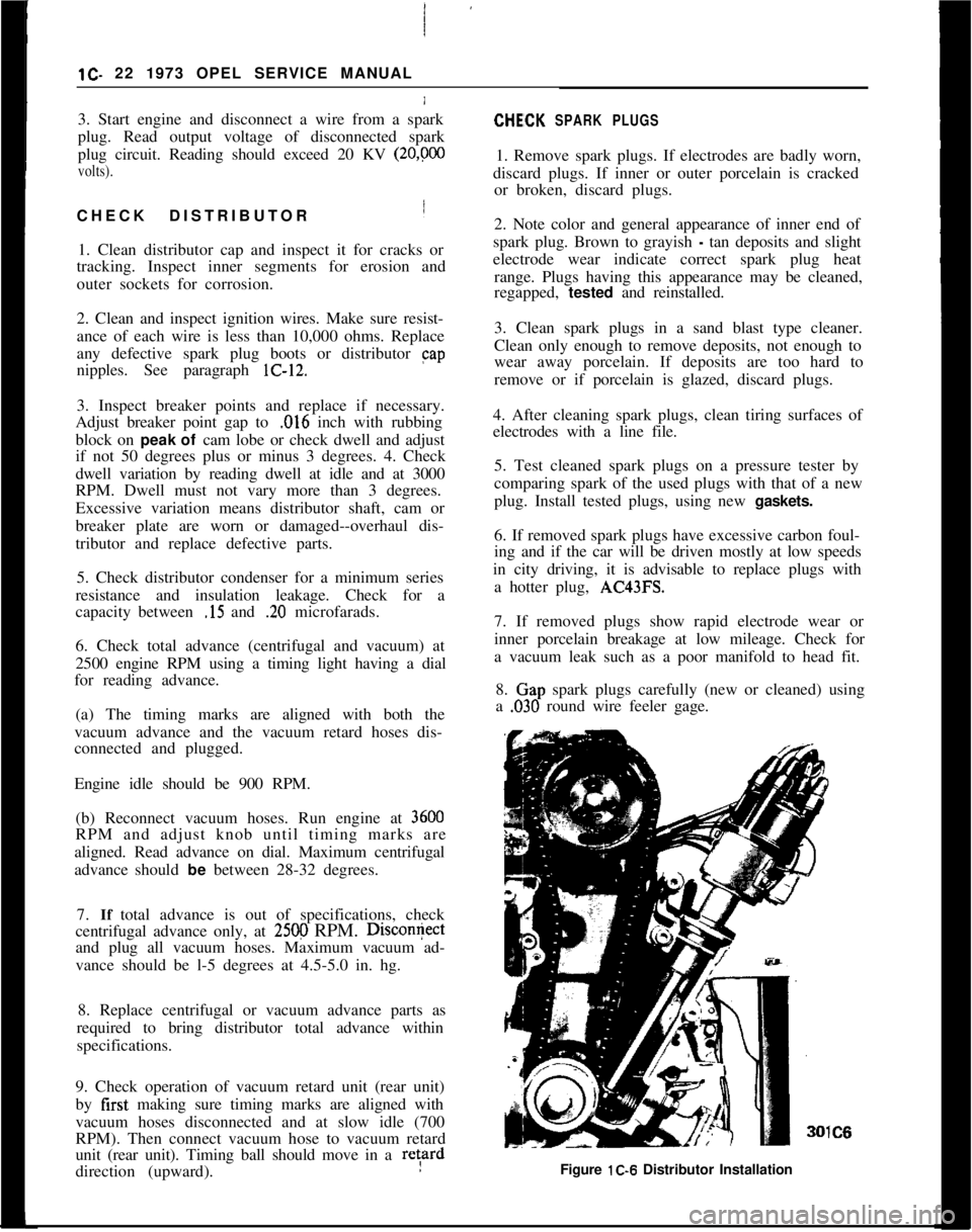
8.
Clap spark plugs carefully (new or cleaned) using
a
,030 round wire feeler gage.IC6
Figure lC-6 Distributor Installation
Page 47 of 625
lC- 261973 OPEL SERVICE MANUAL /
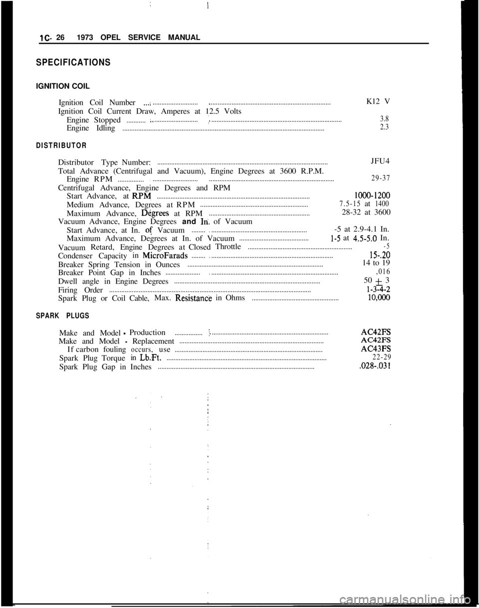
SPECIFICATIONSIGNITION COIL
Ignition Coil Number
.,.:.................................................................................................K12 V
Ignition Coil Current Draw, Amperes at 12.5 Volts
EngineStopped
...........:.........................._............................................................................3.8Engine Idling
....................................................................................................................2.3
DISTRIBUTORDistributor TypeNumber:
..................................................................................................JFU4
Total Advance (Centrifugal and Vacuum), Engine Degrees at 3600 R.P.M.
EngineRPM
..................................................................................................................29-37Centrifugal Advance, Engine Degrees and RPM
StartAdvance,atRPM
........................................................................................lOOO-1200MediumAdvance,DegreesatRPM
..............................................................7.5-15at1400Maximum Advance, Dkgrees at RPM
..........................................................28-32 at 3600
Vacuum Advance, Engine Degrees and
In. of Vacuum
Start Advance, at In. of Vacuum
................................................................-5 at 2.9-4.1 In.
Maximum Advance, Degrees at In. of Vacuum
........................................l-5 at 4.5-5.0 In.
VacuumRetard,EngineDegreesatClosedThrottle
............................................................-5CondenserCapacityinMicroFarads
...............................................................................15-.20Breaker Spring Tension in Ounces
..............................................................................14 to 19
Breaker Point Gap in Inches
..............................................................................................,016Dwell angle in Engine Degrees
....................................................................................50 + 3
Firing Order
....................................................................................................................l-32-2
SparkPlug or CoilCable,Max.Resistancti in Ohms
..................................................10,ooO
SPARK PLUGSMake and Model
-Production................I....................................................................AC42FS
Make and Model
- Replacement...................................................................................AC42FS
Ifcarbonfouling
occurs,use.....................................................................................AC43FS
SparkPlugTorqueinLb:Ft.
............................................................................................22-29Spark Plug Gap in Inches
...........................................................................................028-.03 1
Page 340 of 625
CARBURETOR AND THROTTLE LINKAGE6E- 49DIAGNOSIS
CARBURETORCondition I
Hesitation or Stall Upon Light AccelerationCorrection
1. Check spark plugs and plug gap. Plug gap should
be
,030 in.
2. Check dwell and timing.
3. Adjust carburetor.
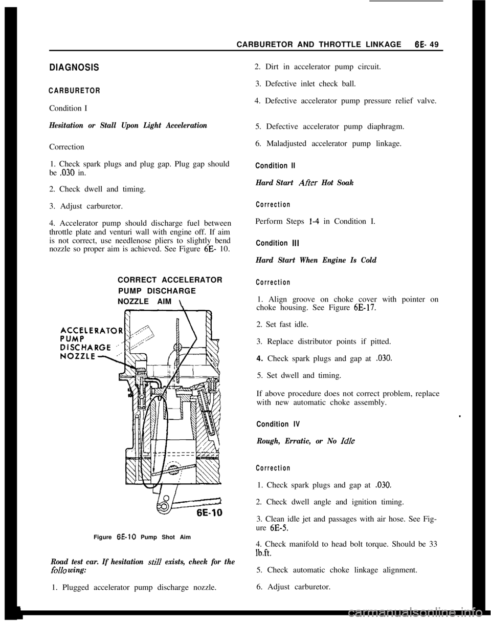
4. Accelerator pump should discharge fuel between
throttle plate and venturi wall with engine off. If aim
is not correct, use needlenose pliers to slightly bend
nozzle so proper aim is achieved. See Figure 6E- 10.
CORRECT ACCELERATOR
PUMP DISCHARGE
NOZZLE AIM
\Figure 6E-10 Pump Shot Aim
Road test car. If hesitation still exists, check for the
folI0 wing:1. Plugged accelerator pump discharge nozzle.2. Dirt in accelerator pump circuit.
3. Defective inlet check ball.
4. Defective accelerator pump pressure relief valve.
5. Defective accelerator pump diaphragm.
6. Maladjusted accelerator pump linkage.
Condition II
Hard Start Afier Hot Soak
CorrectionPerform Steps l-4 in Condition I.
Condition Ill
Hard Start When Engine Is Cold
Correction1. Align groove on choke cover with pointer on
choke housing. See Figure
6E-17.2. Set fast idle.
3. Replace distributor points if pitted.
4. Check spark plugs and gap at
,030.5. Set dwell and timing.
If above procedure does not correct problem, replace
with new automatic choke assembly.
Condition IV
Rough, Erratic, or No Idle
Correction1. Check spark plugs and gap at
,030.2. Check dwell angle and ignition timing.
3. Clean idle jet and passages with air hose. See Fig-
ure
6E-5.4. Check manifold to head bolt torque. Should be 33
lb.ft.5. Check automatic choke linkage alignment.
6. Adjust carburetor.
Page 357 of 625
6G- 661973 OPEL SERVICE MANUAL
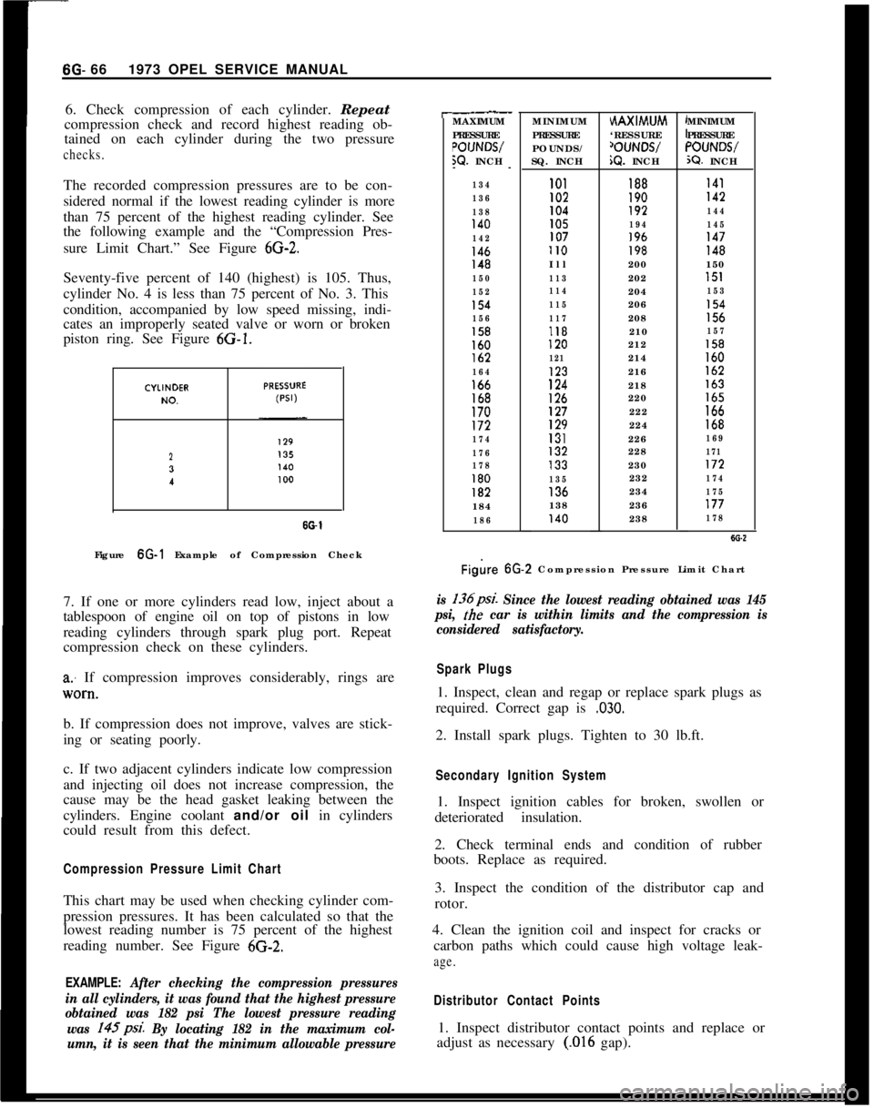
6. Check compression of each cylinder. Repeat
compression check and record highest reading ob-
tained on each cylinder during the two pressurechecks.The recorded compression pressures are to be con-
sidered normal if the lowest reading cylinder is more
than 75 percent of the highest reading cylinder. See
the following example and the “Compression Pres-
sure Limit Chart.” See Figure
6G-2.Seventy-five percent of 140 (highest) is 105. Thus,
cylinder No. 4 is less than 75 percent of No. 3. This
condition, accompanied by low speed missing, indi-
cates an improperly seated valve or worn or broken
piston ring. See Figure 6G-1.
23
I
SO-1Figure 6G-1 Example of Compression Check
7. If one or more cylinders read low, inject about a
tablespoon of engine oil on top of pistons in low
reading cylinders through spark plug port. Repeat
compression check on these cylinders.
a: If compression improves considerably, rings are
lV0*tl.b. If compression does not improve, valves are stick-
ing or seating poorly.
c. If two adjacent cylinders indicate low compression
and injecting oil does not increase compression, the
cause may be the head gasket leaking between the
cylinders. Engine coolant and/or oil in cylinders
could result from this defect.
Compression Pressure Limit ChartThis chart may be used when checking cylinder com-
pression pressures. It has been calculated so that the
lowest reading number is 75 percent of the highest
reading number. See Figure 6G-2.
EXAMPLE: After checking the compression pressures
in all cylinders, it was found that the highest pressure
obtained was 182 psi The lowest pressure reading
was 145psi.
By locating 182 in the maximum col-
umn, it is seen that the minimum allowable pressure
r-.__MAXIMUM
PRESSURE
POIJNWW. INCH
--
134
136
138
140
142
146148
150
152
154
156
158160lb2
164166168170172
174
176
178
180182184
186MINIMUM
PRESSURE
POUNDS/
SQ. INCHHAXIMUM
‘RESSURE
‘OUNWiQ. INCHMINIMUM
PRESSURE“OUNWX?. INCH
101188I41I02190142104192144105194145107196147II0198148Ill200150
113202151
114204153
115206154
117208156118210157120212158
121214160123216162
124218163
126220165127222166129224168131226169132228171133230172
135232174136234175138236177140238178
Figire 6G.2 Compression Pressure Limit Chart
is 136psi. Since the lowest reading obtained was 145
psi,
the car is within limits and the compression is
considered satisfactory.
Spark Plugs1. Inspect, clean and regap or replace spark plugs as
required. Correct gap is
,030.2. Install spark plugs. Tighten to 30 lb.ft.
Secondary Ignition System1. Inspect ignition cables for broken, swollen or
deteriorated insulation.
2. Check terminal ends and condition of rubber
boots. Replace as required.
3. Inspect the condition of the distributor cap and
rotor.
4. Clean the ignition coil and inspect for cracks or
carbon paths which could cause high voltage leak-
age.
Distributor Contact Points1. Inspect distributor contact points and replace or
adjust as necessary
(.016 gap).
Page 359 of 625
6G- 68 1973 OPEL SERVICE MANUAL
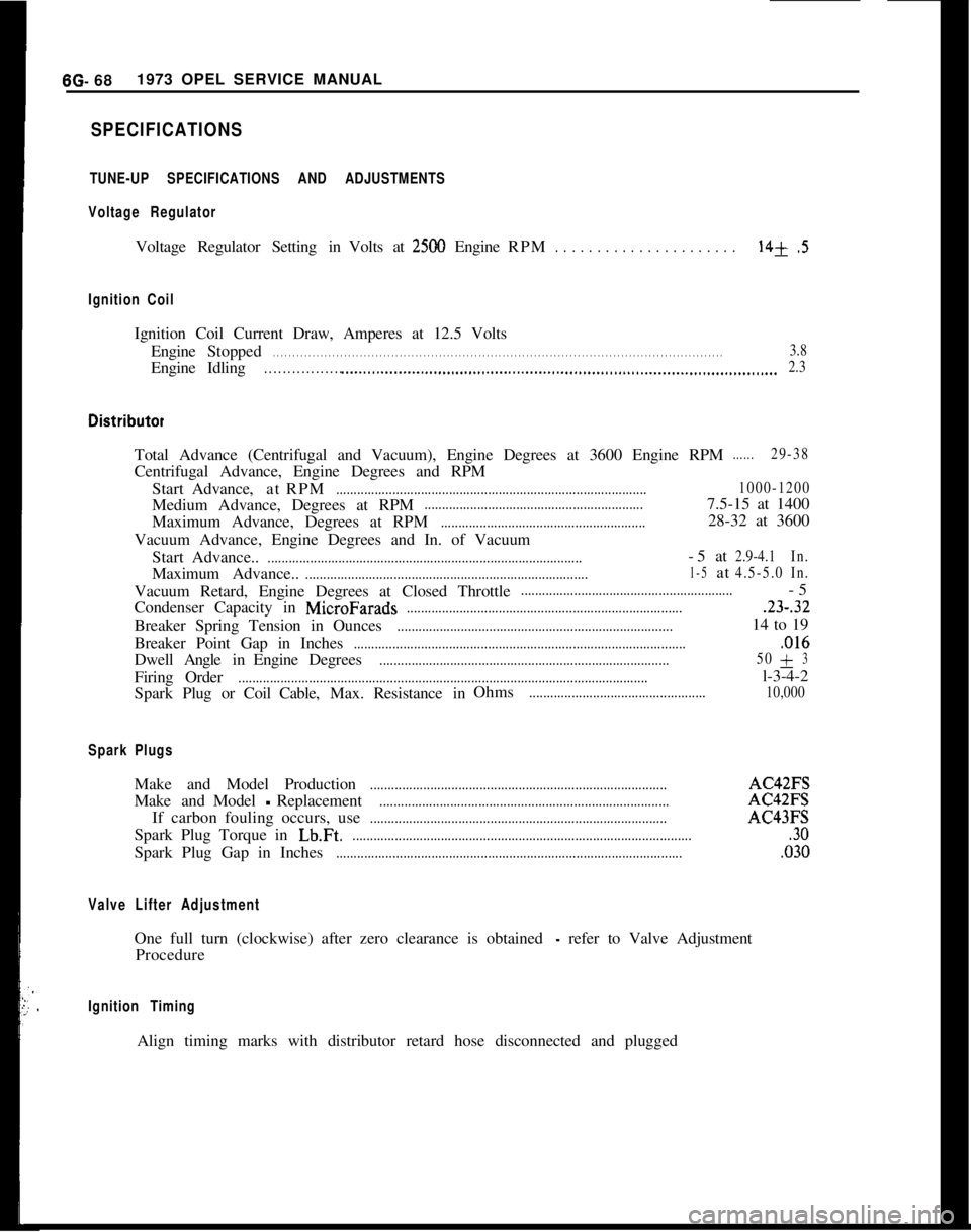
SPECIFICATIONS
TUNE-UP SPECIFICATIONS AND ADJUSTMENTS
Voltage Regulator
Voltage Regulator Setting in Volts at2500 Engine RPM. . . . . . . . . . . . . . . . . . . . . .14+.5
Ignition Coil
Ignition Coil Current Draw, Amperes at 12.5 Volts
Engine Stopped
. . . . . . . . . . . . . . . . . . . . . . . . . . . . . . . . . . . . \
. . . . . . . . . . . . . . . . . . . . . . . . . . . . . . . . . . . . \
. . . . . . . . . . . . . . . . . . . . . . . . . . . . . . . . . . . . \
. . . . . .3.8
EngineIdling. . . . . . . . . . . . . . . . . .._.....................................................................\
........................... 2.3
Total Advance (Centrifugal and Vacuum), Engine Degrees at 3600 Engine \
RPM......29-38
Centrifugal Advance, Engine Degrees and RPM
Start Advance, atRPM
........................................................................\
................ 1000-1200
Medium Advance, Degrees at RPM..............................................................7.5-15 at 1400
Maximum Advance, Degrees at RPM
..........................................................28-32 at 3600
Vacuum Advance, Engine Degrees and In. of Vacuum Start Advance..
........................................................................\
.................-5at2.9-4.1 In.
Maximum Advance..........................................................................\
........1-5at4.5-5.0In.
Vacuum Retard, Engine Degrees at Closed Throttle............................................................-5
Condenser Capacity in
MicroFarads........................................................................\
.......23-.32
Breaker Spring Tension in Ounces........................................................................\
......14 to 19
Breaker Point Gap in Inches
........................................................................\
......................,016
Dwell AngleinEngine Degrees........................................................................\
.......... 50+3
Firing
Order........................................................................\
............................................l-3-4-2
Spark Plug or Coil Cable,Max.Resistance in Ohms
..................................................
10,000
Spark Plugs
Make and Model Production........................................................................\
............AC42FS
Make andModel
-Replacement........................................................................\
..........AC42FS
If carbon fouling occurs, use
........................................................................\
............AC43FS
Spark Plug Torque in
Lb.Ft.........................................................................\
.........................30
Spark Plug Gap in Inches........................................................................\
..........................,030
Valve Lifter Adjustment
One full turn (clockwise) after zero clearance is obtained - refer to Valve Adjustment
Procedure
Ignition Timing
Align timing marks with distributor retard hose disconnected and plugged\