jack points OPEL GT-R 1973 Service Manual
[x] Cancel search | Manufacturer: OPEL, Model Year: 1973, Model line: GT-R, Model: OPEL GT-R 1973Pages: 625, PDF Size: 17.22 MB
Page 13 of 625
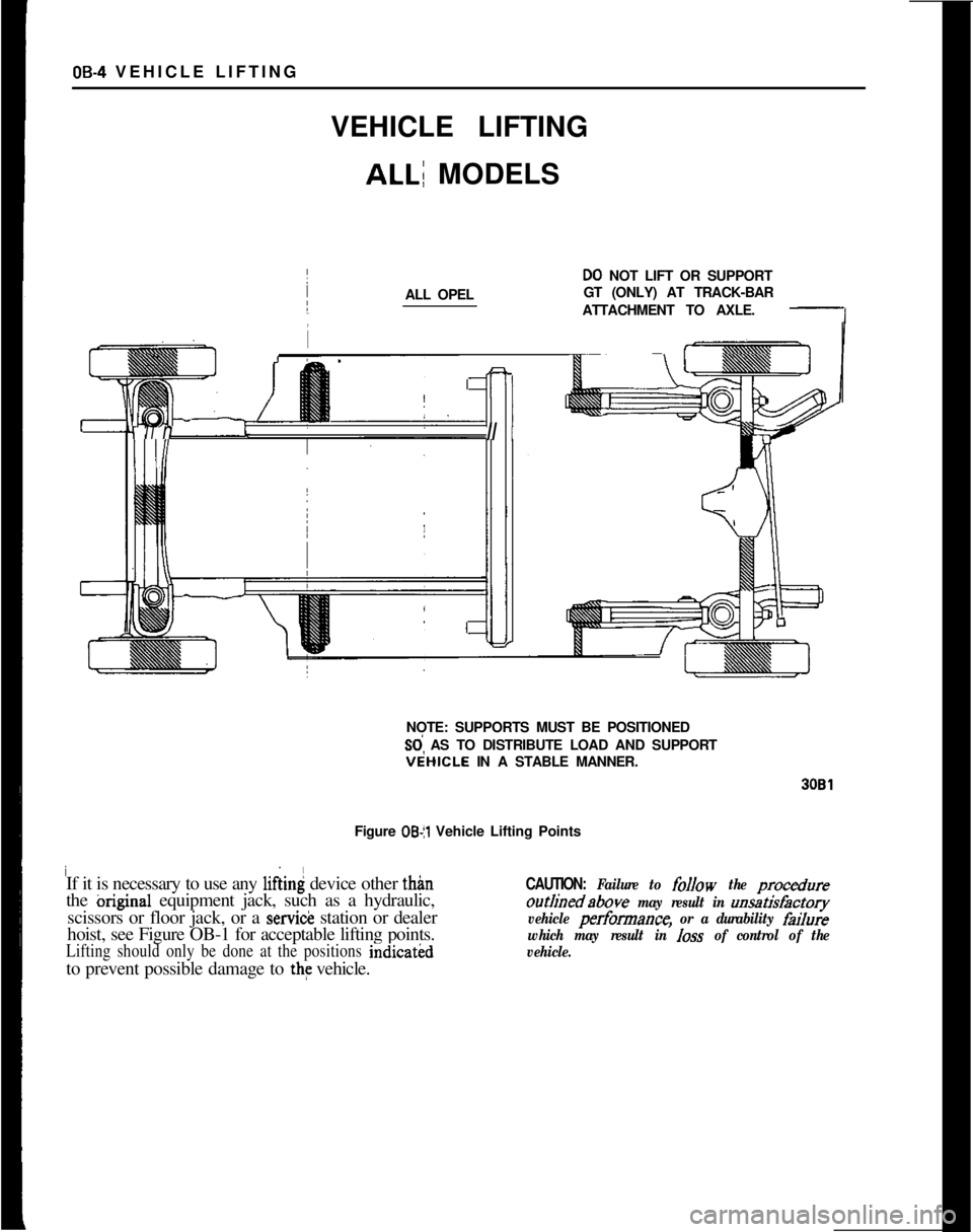
08-4 VEHICLE LIFTING ~
~ VEHICLE LIFTING
ALL; MODELS
ALL OPEL
DO NOT LIFT OR SUPPORT
GT (ONLY) AT TRACK-BAR
ATTACHMENT TO AXLE.
i
FIT nII IINOTE: SUPPORTS MUST BE POSITIONEDSd AS TO DISTRIBUTE LOAD AND SUPPORTVtiHICLE IN A STABLE MANNER.
3081Figure
OB
scissors or floor jack, or a
servicJz station or dealer
hoist, see Figure OB-1 for acceptable lifting points.
Lifting should only be done at the positions indicatkdto prevent possible damage to the vehicle.
CAUTION: Failure to follow the procedure
outljnedabove may result in unsatisfactory
vehicle perfomance,
or a durability failure
which may result in
loss of control of the
vehicle.
Page 173 of 625
3A- 6 1973 OPEL SERVICE MANUAL
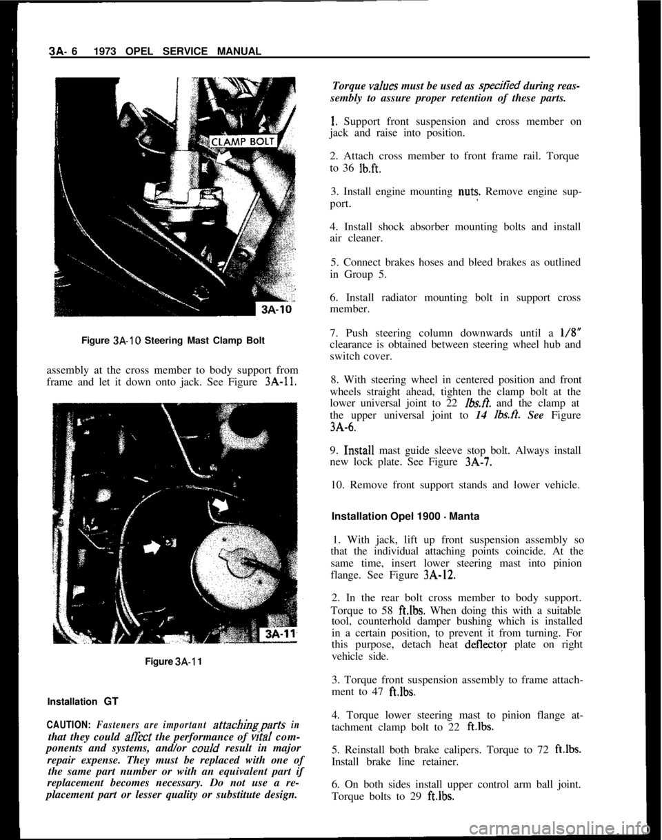
Figure 3A-10 Steering Mast Clamp Bolt
assembly at the cross member to body support from
frame and let it down onto jack. See Figure
3A-11.
Figure 3A-1 1
Installation
GT
CAUTION: Fasteners are important attachingparts in
that they could affect the performance of vitaI com-
ponents and systems, and/or
coo/d result in major
repair expense. They must be replaced with one of the same part number or with an equivalent part if
replacement becomes necessary. Do not use a re-
placement part or lesser quality or substitute design. Torque
values
must be used as speciiied during reas-
sembly to assure proper retention of these parts.
I. Support front suspension and cross member on
jack and raise into position.
2. Attach cross member to front frame rail. Torque
to 36
lb.ft.
3. Install engine mounting nut? Remove engine sup-
port.
4. Install shock absorber mounting bolts and install
air cleaner.
5. Connect brakes hoses and bleed brakes as outlined
in Group 5.
6. Install radiator mounting bolt in support cross
member.
7. Push steering column downwards until a
l/8”
clearance is obtained between steering wheel hub and
switch cover.
8. With steering wheel in centered position and front
wheels straight ahead, tighten the clamp bolt at the
lower universal joint to 22
fbs.fi. and the clamp at
the upper universal joint to 14
lbs.ft. See Figure
3A-6.
9. Inr;tall mast guide sleeve stop bolt. Always install
new lock plate. See Figure
3A-7.
10. Remove front support stands and lower vehicle.
Installation Opel 1900 - Manta
1. With jack, lift up front suspension assembly so
that the individual attaching points coincide. At the
same time, insert lower steering mast into pinion
flange. See Figure
3A-12.
2. In the rear bolt cross member to body support.
Torque to 58
ft.lbs. When doing this with a suitable
tool, counterhold damper bushing which is installed
in a certain position, to prevent it from turning. For
this purpose, detach heat
deflectqr plate on right
vehicle side.
3. Torque front suspension assembly to frame attach-
ment to 47
ft.lbs.
4. Torque lower steering mast to pinion flange at-
tachment clamp bolt to 22
ft.lbs.
5. Reinstall both brake calipers. Torque to 72 ft.lbs.
Install brake line retainer.
6. On both sides install upper control arm ball joint.
Torque bolts to 29
ft.lbs.
Page 174 of 625
FRONT SUSPENSION3A- 7
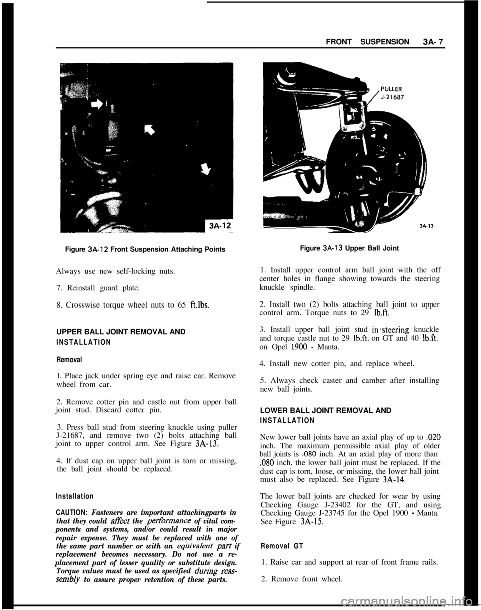
Figure 3A-12 Front Suspension Attaching Points
Always use new self-locking nuts.
7. Reinstall guard plate.
8. Crosswise torque wheel nuts to 65 ft.lbs.UPPER BALL JOINT REMOVAL AND
INSTALLATION
RemovalI. Place jack under spring eye and raise car. Remove
wheel from car.
2. Remove cotter pin and castle nut from upper ball
joint stud. Discard cotter pin.
3. Press ball stud from steering knuckle using puller
J-21687, and remove two (2) bolts attaching ball
joint to upper control arm. See Figure 3A-13.
4. If dust cap on upper ball joint is torn or missing,
the ball joint should be replaced.
Installation
CAUTION:
Fasteners are important attachingparts in
that they could
afEct the pertkmance of vital com-
ponents and systems, and/or could result in major
repair expense. They must be replaced with one of
the same part number or with an
equivaknt pa-t if
replacement becomes necessary. Do not use a re-
placement part of lesser quality or substitute design.
Torque values must be used as specified
durikg reas-
sembly to assure proper retention of these parts.Figure 3A-13 Upper Ball Joint
1. Install upper control arm ball joint with the off
center holes in flange showing towards the steering
knuckle spindle.
2. Install two (2) bolts attaching ball joint to upper
control arm. Torque nuts to 29 Ibft.
3. Install upper ball joint stud in%eering knuckle
and torque castle nut to 29
Ib.ft. on GT and 40 lb&.
on Opel
1900 - Manta.
4. Install new cotter pin, and replace wheel.
5. Always check caster and camber after installing
new ball joints.
LOWER BALL JOINT REMOVAL AND
INSTALLATIONNew lower ball joints have an axial play of up to
,020inch. The maximum permissible axial play of older
ball joints is
,080 inch. At an axial play of more than
,080 inch, the lower ball joint must be replaced. If the
dust cap is torn, loose, or missing, the lower ball joint
must also be replaced. See Figure
3A-14.The lower ball joints are checked for wear by using
Checking Gauge J-23402 for the GT, and using
Checking Gauge J-23745 for the Opel 1900
- Manta.
See Figure
3A-15.
Removal GT1. Raise car and support at rear of front frame rails.
2. Remove front wheel.
Page 211 of 625
3E. 441973 OPEL SERVICE’MANUAL
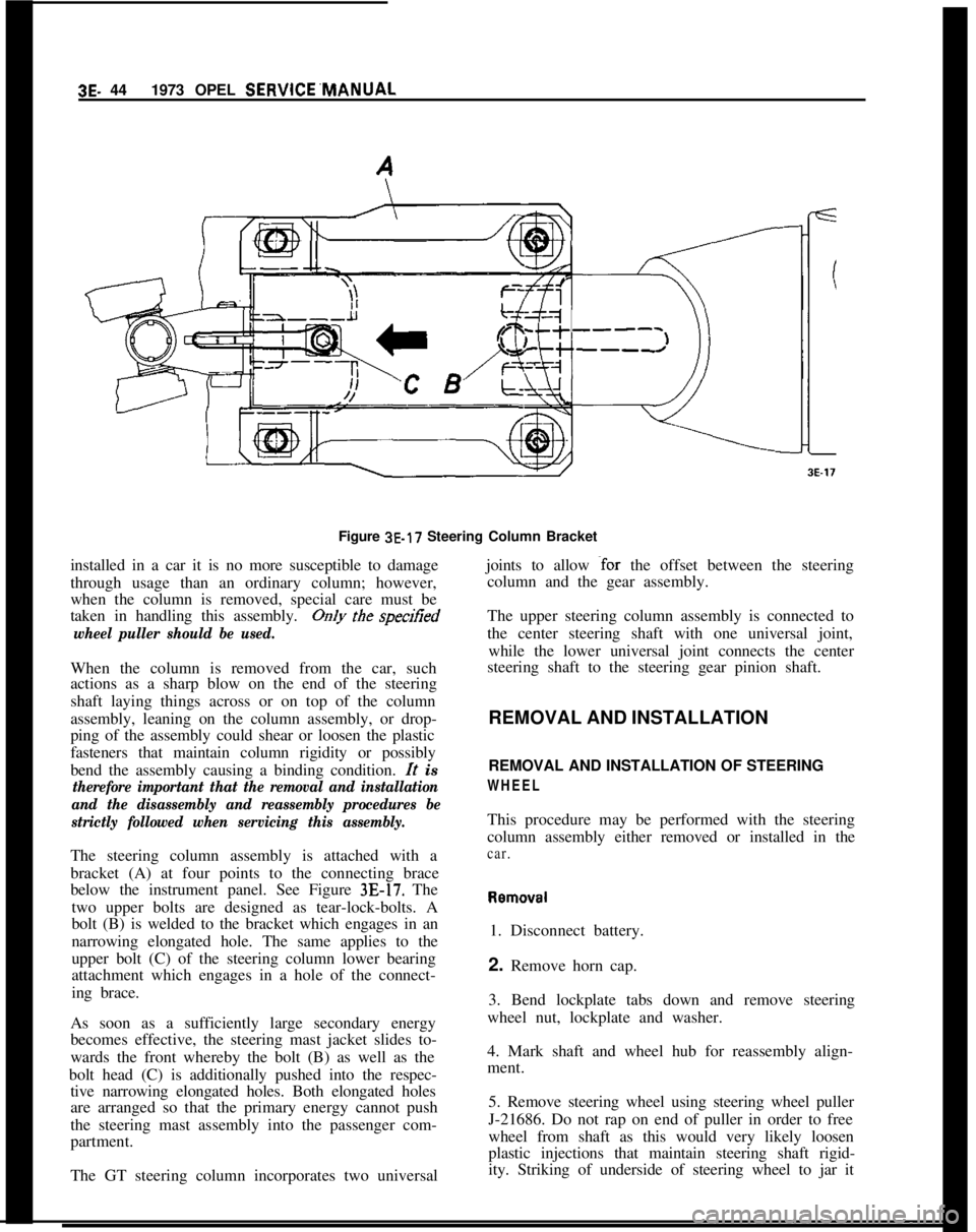
Figure 3E-17 Steering Column Bracket
installed in a car it is no more susceptible to damage
through usage than an ordinary column; however,
when the column is removed, special care must be
taken in handling this assembly.Only the speufied
wheel puller should be used.When the column is removed from the car, such
actions as a sharp blow on the end of the steering
shaft laying things across or on top of the column
assembly, leaning on the column assembly, or drop-
ping of the assembly could shear or loosen the plastic
fasteners that maintain column rigidity or possibly
bend the assembly causing a binding condition.
It is
therefore important that the removal and installation
and the disassembly and reassembly procedures be
strictly followed when servicing this assembly.The steering column assembly is attached with a
bracket (A) at four points to the connecting brace
below the instrument panel. See Figure
3E-17. The
two upper bolts are designed as tear-lock-bolts. A
bolt (B) is welded to the bracket which engages in an
narrowing elongated hole. The same applies to the
upper bolt (C) of the steering column lower bearing
attachment which engages in a hole of the connect-
ing brace.
As soon as a sufficiently large secondary energy
becomes effective, the steering mast jacket slides to-
wards the front whereby the bolt (B) as well as the
bolt head (C) is additionally pushed into the respec-
tive narrowing elongated holes. Both elongated holes
are arranged so that the primary energy cannot push
the steering mast assembly into the passenger com-
partment.
The GT steering column incorporates two universaljoints to allow
~for the offset between the steering
column and the gear assembly.
The upper steering column assembly is connected to
the center steering shaft with one universal joint,
while the lower universal joint connects the center
steering shaft to the steering gear pinion shaft.
REMOVAL AND INSTALLATION
REMOVAL AND INSTALLATION OF STEERING
WHEELThis procedure may be performed with the steering
column assembly either removed or installed in the
car.Removal
1. Disconnect battery.
2. Remove horn cap.
3. Bend lockplate tabs down and remove steering
wheel nut, lockplate and washer.
4. Mark shaft and wheel hub for reassembly align-
ment.
5. Remove steering wheel using steering wheel puller
J-21686. Do not rap on end of puller in order to free
wheel from shaft as this would very likely loosen
plastic injections that maintain steering shaft rigid-
ity. Striking of underside of steering wheel to jar it
Page 289 of 625
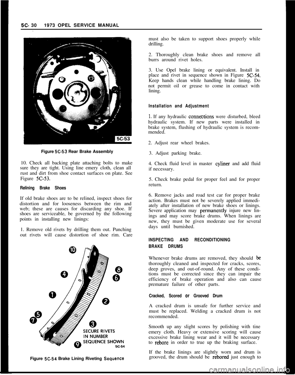
Figure 5C-53 Rear Brake Assembly
10. Check all backing plate attaching bolts to make
sure they are tight. Using line emery cloth, clean all
rust and dirt from shoe contact surfaces on plate. See
Figure Z-53.
Relining Brake ShoesIf old brake shoes are to be relined, inspect shoes for
distortion and for looseness between the rim and
web; these are causes for discarding any shoe. If
shoes are serviceable, be governed by the following
points in installing new linings:
1. Remove old rivets by drilling them out. Punching
out rivets will cause distortion of shoe rim. Care5C- 301973 OPEL SERVICE MANUAL
must also be taken to support shoes properly while
drilling.
2. Thoroughly clean brake shoes and remove all
burrs around rivet holes.
3. Use Opel brake lining or equivalent. Install in
place and rivet in sequence shown in Figure
Z-54.Keep hands clean while handling brake lining. Do
not permit oil or grease to come in contact with
lining.
Installation and Adjustment
1. If any hydraulic conne&tions were disturbed, bleed
hydraulic system. If new parts were installed in
brake system, flushing of hydraulic system is recom-
mended.
2. Adjust rear wheel brakes.
3. Adjust parking brake.
4. Check fluid level in master cyliner and add fluid
if necessary.
5. Check brake pedal for proper feel and for proper
return.
6. Remove jacks and road test car for proper brake
action. Brakes must not be severely applied immedi-
ately after installation of new brake shoes or linings.
Severe application may perinanently injure new lin-
ings and may score brake drums. When linings are
new, they must be given moderate use for several
days until burnished.
INSPECTING AND RECONDITIONING
BRAKE DRUMSWhenever brake drums are removed, they should
bethoroughly cleaned and inspected for cracks, scores,
deep groves, and out-of-round. Any of these condi-
tions must be corrected since they can impair the
efficiency of brake operation and also can cause
premature failure of other parts.
Cracked, Scored or Grooved DrumA cracked drum is unsafe for further service and
must be replaced. Welding a cracked drum is not
recommended.
Smooth up any slight scores by polishing with tine
emery cloth. Heavy or extensive scoring will cause
excessive brake lining wear and it will be necessary
to rebore in order to true up the braking surface.
Figure 5C.54 Brake Lining Riveting
SequenceIf the brake linings are slightly worn and drum is
grooved, the drum should be rebored just enough to
Page 332 of 625
FUEL SYSTEM6C- 41
covered with sound deadening compound. See Fig-
ure
6C-10.7. Remove fuel tank vent hose and tiller hose. See
Figure 6C- 11.
8. Remove fuel tank attaching bolts and gauge wire
and remove tank.
Installation
1. Install tank and tighten attaching bolts.
2. Replace gauge wire. Install vent hose, making cer-
tain it is not kinked and seal vent hose hole in floor.
3. Install spare tire support attaching brackets, sup-
port panel, hold-down, and brackets.
4. Install spare tire and jack.
5. Install fuel line and rubber cap.
6. Connect battery.FUEL LINES. FUEL GAUGE TANK UNITS
All fuel lines are plastic and have an outside diameter
of
,240 inches. Unlike metal lines, plastic lines are
not flared.
When replacing a plastic line, place the line in hot
water to make it flexible. Using the old line as a
pattern, form the new line. Let the line cool com-
pletely, then route it in the same location as the old
line. To prevent chafing against the underbody, nine
(9) rubber grommets are placed at points on the line
between the fuel tank and the fuel pump. When re-
placing fuel gauge tank units, coat gasket on both
sides and first threads of attaching screws with seal-
ing compound.
CLEANING FUEL TANK
1. Remove fuel tank.
2. Empty fuel tank through filler neck.
3. Remove fuel gauge tank unit, together with suc-
tion tube and screen. Clean screen and blow out from
cover side. Flush fuel tank.
SPECIFICATIONSFuel Tank Capacity (Gallons)
Opel 1900 and Manta
....................................................................................................11.9GT
....................................................................................................................................13.2FuelGaugeType
........................................................................................................Electrical
Fuel Pump Type
......................................................................................................Mechanical
Fuel Pump Drive
..................................................................................Eccentric on Camshaft
Fuel Pump Pressure at 1950 (RPM)................................................................3.1 to 3.7 P.S.I.FuelFilter
............................................................................................................In-LineFilter