engine coolant OPEL GT-R 1973 User Guide
[x] Cancel search | Manufacturer: OPEL, Model Year: 1973, Model line: GT-R, Model: OPEL GT-R 1973Pages: 625, PDF Size: 17.22 MB
Page 325 of 625
6B- 341973 OPEL SERVICE MANUAL
test by partially draining the cooling system and dis-
connecting the water outlet housing from the ther-
mostat housing which is mounted on the right front
side of cylinder head.
The standard thermostat valve should start to open
at 189 degrees F and fully open at approximately 212
degrees F. If thermostat does not operate at specified
temperatures, it should be replaced as it cannot be
repaired.MAJOR REPAIR
WATER PUMP REPAIRSThe water pump bearing outer race is shrunk fit into
the water pump cover. For this reason the cover,
shaft bearing, and hub are not repairable.
Water Pump RemovalOpel radiators do not have a drain plug. Drain radia-
tor by first, loosening radiator cap, then remove
lower hose from lower radiator tank.
1. Drain coolant into a clean container. Remove
radiator and shroud.
2. Remove fan belt.
3. Remove fan blade and pulley on water pump shaft.
4. Disconnect inlet hose and heater hose from water
pump. Remove bolts, pump assembly and gasket
from timing chain cover.
5. Check pump shaft bearing for end play or rough-
ness in operation. If bearings are not in serviceable
condition, the assembly must be replaced.
Water Pump Installation1. Make sure the gasket surfaces on pump and timing
chain covers are clean. Install pump assembly with
new gasket. Bolts must be tightened uniformly.
Torque to 11 lb. ft.
2. Install radiator and shroud. Connect radiator hose
to pump inlet and heater hose to nipple.
3. Install fan pulley and fan blade, tighten attaching
bolts securely. Install belts and adjust for proper
tension.4. Fill cooling system and check
,for leaks at pump
and hose joints.
RADIATOR REMOVAL AND INSTALLATION
RemovalI. Loosen radiator cap, then remove lower radiator
hose and drain radiator coolant into suitable con-
tainer.
2. On vehicles with automatic transmission, unscrew
oil lines from connectors on lower radiator tank and
plug lines. On GT models with automatic transmis-
sion the lines have to be disconnected at the coupling
before removing from the tank. It is essential that no
dirt enters the oil lines. When unscrewing oil lines,
hold connectors on lower radiator tank with pliers to
avoid leakages. Ensure that no dirt enters oil cooler.
3. Remove lower attaching nut and slide radiator
upward and out of engine compartment.
Installation1. Install radiat,or into engine compartment and se-
cure lower attaching nut.
2. On vehicles with automatic transmissions, fasten
oil cooler lines to lower radiator tank. It is essential
that no dirt enters the oil lines. When tightening oil
lines, hold connectors on lower radiator tank with
pliers to avoid leakages. Ensure that no dirt enters oil
cooler. Torque to 1 I-15
lbs.ft.3. Install lower radiator hose and add collected coo-
lant.
All Opels are provided with a radiator initial fill of
an antifreeze solution containing corrosion inhibitor.
The antifreeze has either a glycol or glycerin base
and protects the engine against freezing, down to
minus 22 degrees F. (minus 30 degrees C.). Before
the start of the cold season, coolant must be checked
with a hydrometer and if necessary, brought to the
necessary specific gravity by adding anti-freeze with
a glycol or glycerin base. As the specific gravities of
all anti- freeze solutions having a glycol or glycerin
base are practically the same, the hydrometer can be
used for all these types. Because of the tolerances of
the hydrometer, or slight differences in specific
gravity, variations of plus or minus 5 degrees can be
expected. Coolant must be checked at a temperature
of plus 68 degrees F. (plus 20 degrees C.)
Page 357 of 625
6G- 661973 OPEL SERVICE MANUAL
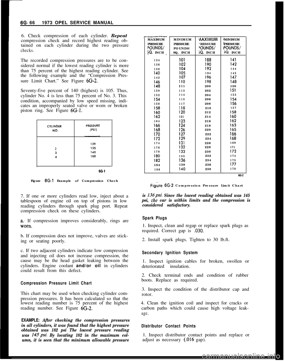
6. Check compression of each cylinder. Repeat
compression check and record highest reading ob-
tained on each cylinder during the two pressurechecks.The recorded compression pressures are to be con-
sidered normal if the lowest reading cylinder is more
than 75 percent of the highest reading cylinder. See
the following example and the “Compression Pres-
sure Limit Chart.” See Figure
6G-2.Seventy-five percent of 140 (highest) is 105. Thus,
cylinder No. 4 is less than 75 percent of No. 3. This
condition, accompanied by low speed missing, indi-
cates an improperly seated valve or worn or broken
piston ring. See Figure 6G-1.
23
I
SO-1Figure 6G-1 Example of Compression Check
7. If one or more cylinders read low, inject about a
tablespoon of engine oil on top of pistons in low
reading cylinders through spark plug port. Repeat
compression check on these cylinders.
a: If compression improves considerably, rings are
lV0*tl.b. If compression does not improve, valves are stick-
ing or seating poorly.
c. If two adjacent cylinders indicate low compression
and injecting oil does not increase compression, the
cause may be the head gasket leaking between the
cylinders. Engine coolant and/or oil in cylinders
could result from this defect.
Compression Pressure Limit ChartThis chart may be used when checking cylinder com-
pression pressures. It has been calculated so that the
lowest reading number is 75 percent of the highest
reading number. See Figure 6G-2.
EXAMPLE: After checking the compression pressures
in all cylinders, it was found that the highest pressure
obtained was 182 psi The lowest pressure reading
was 145psi.
By locating 182 in the maximum col-
umn, it is seen that the minimum allowable pressure
r-.__MAXIMUM
PRESSURE
POIJNWW. INCH
--
134
136
138
140
142
146148
150
152
154
156
158160lb2
164166168170172
174
176
178
180182184
186MINIMUM
PRESSURE
POUNDS/
SQ. INCHHAXIMUM
‘RESSURE
‘OUNWiQ. INCHMINIMUM
PRESSURE“OUNWX?. INCH
101188I41I02190142104192144105194145107196147II0198148Ill200150
113202151
114204153
115206154
117208156118210157120212158
121214160123216162
124218163
126220165127222166129224168131226169132228171133230172
135232174136234175138236177140238178
Figire 6G.2 Compression Pressure Limit Chart
is 136psi. Since the lowest reading obtained was 145
psi,
the car is within limits and the compression is
considered satisfactory.
Spark Plugs1. Inspect, clean and regap or replace spark plugs as
required. Correct gap is
,030.2. Install spark plugs. Tighten to 30 lb.ft.
Secondary Ignition System1. Inspect ignition cables for broken, swollen or
deteriorated insulation.
2. Check terminal ends and condition of rubber
boots. Replace as required.
3. Inspect the condition of the distributor cap and
rotor.
4. Clean the ignition coil and inspect for cracks or
carbon paths which could cause high voltage leak-
age.
Distributor Contact Points1. Inspect distributor contact points and replace or
adjust as necessary
(.016 gap).
Page 358 of 625
2. If inspection of contact points indicates excessive
burning, pitting or wear, check condenser and re-
place if necessary.
3. Inspect all connections and wires in the primary
ignition circuit. Correct any abnormal conditions
found.Carburetor1. Clean fuel strainer in fuel pump. To prevent fuel
leakage in pump, disconnect “IN” line from pump
and raise end above fuel level. The in-line fuel filter
should be replaced every 12,000 miles or every 12
months.
2. Check for freedom of choke valve operation and
clean shaft if necessary, with suitable solvent.
3. Inspect throttle cable or linkage bracket and re-
turn spring for wear. With helper depressing acceler-
ator pedal to floor, check for wide open throttle.
Adjust accelerator pedal height so wide open throttle
is obtained when pedal is within
l/2 inch from floor.
Lubricate linkage pivot points with engine oil.
Air CleanerCheck paper element every 6,000 miles and replace
every
24,ooO miles. If a vehicle is operated in dusty
territory, check condition of air cleaner element
more frequently and replace if necessary.
Fan Belt1. Inspect belt for wear, cracks or frayed points.
Replace and/or adjust as necessary. Specified ten-
sion for belt using Gauge J-23600 is 45 lbs.
Cooling System1. Inspect the radiator, water pump, cylinder head
areas and all radiator and heater hose connections
for evidence of engine coolant leaks.
2. Inspect all hoses for deterioration from gas and oil
contact. Correct as required.
Inspection should be made with engine operating at
normal temperature, cooling system completely
filled, temperature control lever fully open and nor-
mal pressure in the system. Normal pressure should
be 13.2 to 15.2 psi.
Engine Lubrication SystemInspect engine for evidence of oil leakage. Correctany abnormal condition with sealastic or new seals
and gaskets.
Battery
1. Inspect battery, battery mount and cables and
check electrolyte level. Proper level should be just
above the cell plates.
CAUTION:Do not over fill.
2. Determine the serviceability of the battery by ap-
plying the 421 Battery Test.
Positive Crankcase VentilationClean crankcase ventilator metered orifice in the in-
take manifold fitting every 6,000 miles. Also all hoses
and fittings should be inspected, cleaned and re-
placed, if necessary.
To clean, remove rubber hose from metered orifice
and apply air pressure to orifice to remove any for-
eign particles that may be trapped.
Valve Lifter AdjustmentRefer to Engine Mechanical and Mounts section for
valve lifter adjustment procedure.
Engine Tune-Up Instrument ChecksThe following instrument checks and adjustments
serve as a final check on engine condition. These
checks may discover some new problems that may
not have been obvious before. The engine is also
given its final adjustments that will assure maximum
performance, reliability, and proper emission con-
trol.
Refer to Electrical Group for checking procedures of
the following:
Cranking Voltage Check
Ignition Timing
Distributor Advance
Ignition Output
Secondary Resistance
Current Output and Voltage Setting
Idle Speed and Mixture AdjustmentsRefer to carburetor section.
Page 443 of 625
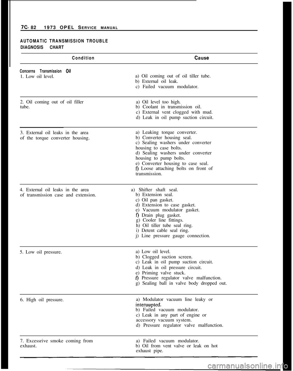
7C- 821973 OPEL SERVICE MANUALAUTOMATIC TRANSMISSION TROUBLE
DIAGNOSIS CHART
Condition
CEllE.e
Concerns Transmission Oil1. Low oil level.a) Oil coming out of oil tiller tube.
b) External oil leak.
c) Failed vacuum modulator.
2. Oil coming out of oil filler
tube.a) Oil level too high.
b) Coolant in transmission oil.
c) External vent clogged with mud.
d) Leak in oil pump suction circuit.
3. External oil leaks in the area
of the torque converter housing.a) Leaking torque converter.
b) Converter housing seal.
c) Sealing washers under converter
housing to case bolts.
d) Sealing washers under converter
housing to pump bolts.
e) Converter housing to case seal.
fj Loose attaching bolts on front of
transmission.
4. External oil leaks in the area
of transmission case and extension.a) Shifter shaft seal.
b) Extension seal.
c) Oil pan gasket.
d) Extension to case gasket.
e) Vacuum modulator gasket.
f) Drain plug gasket.
g) Cooler line fittings.
h) Oil tiller tube seal ring.
i) Detent cable seal ring.
j) Line pressure gauge connection.
5. Low oil pressure.a) Low oil level.
b) Clogged suction screen.
c) Leak in oil pump suction circuit.
d) Leak in oil pressure circuit.
e) Priming valve stuck.
t) Pressure regulator valve malfunction.
g) Sealing ball in valve body dropped out.
6. High oil pressure.a) Modulator vacuum line leaky orinteruupted.
b) Failed vacuum modulator.
c) Leak in any part of engine or
accessory vacuum system.
d) Pressure regulator valve malfunction.
7. Excessrive smoke coming from
exhaust.a) Failed vacuum modulator.
b) Oil from vent valve or leak on hot
exhaust pipe.
Page 514 of 625

HEATER SYSTEM - GT9A- 5
MAJOR REPAIR
REMOVAL AND INSTALLATION INSTRUMENT
PANEL FRESH AIR OUTLET
Removal
1. Remove instrument panel cover assembly. Refer
to Group 1.
2. Snap grille out of outlet.
3. Remove knob from lever and remove outlet.
Installation
1. Install outlet and knob onto lever.
2. Snap grille into outlet.
3.
Install instrument panel cover assembly. Refer to
Group 1.
REMOVAL AND INSTALLATION KICK PANEL
FRESH AIR OUTLET
Removal
Using a screwdriver, carefully pry out outlet.
Installation
Install outlet.
REMOVAL AND INSTALLATION BLOWER
SWITCH
Removal
i. Remove instrument panel assembly. Refer to
Group 1.
2. Unscrew switch assembly from panel.
Installation
1. Screw switch assembly to instrument panel.
2. Install instrument panel assembly. Refer to Group
1.
REMOVAL AND INSTALLATION HEATER
Ramova!
1. Remove lower radiator hose, drain, and collect
coolant. 2. Detach coolant feed (A) and return (B) hoses, in
engine compartment from heater core. See Figure
9A-5.
Figure 9A-5 Heater Hose Connections
3. In engine compartment remove hood lock control
cable retaining clip and cable from lock bar. See Figure
9A-6.
Figure 9A-6 Hood Release Control Cable
4. Remove console shift cover between seats using
the following instructions:
a. Remove ash tray and remove two screws under it.
Page 517 of 625
9A-8 1973 OPEL SERVICE MANUAL
Installation
1. Install heater blower and case assembly, securing
with one (1) bolt at the top and two (2) nuts from the
bottom. See Figure
9A-15.
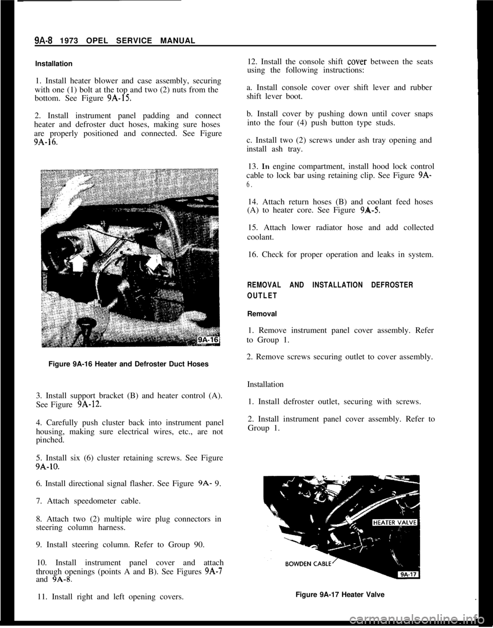
2. Install instrument panel padding and connect
heater and defroster duct hoses, making sure hoses
are properly positioned and connected. See Figure
9A-16.
Figure 9A-16 Heater and Defroster Duct Hoses
3. Install support bracket (B) and heater control (A).
See Figure
9A-12.
4. Carefully push cluster back into instrument panel
housing, making sure electrical wires, etc., are not
pinched.
5. Install six (6) cluster retaining screws. See Figure
9A-10.
6. Install directional signal flasher. See Figure
9A- 9.
7. Attach speedometer cable.
8. Attach two (2) multiple wire plug connectors in
steering column harness.
9. Install steering column. Refer to Group 90.
10. Install instrument panel cover and attach
through openings (points A and B). See Figures
9A-7
and 9A-8.
11. Install right and left opening covers. 12. Install the console shift
cover
between the seats
using the following instructions:
a. Install console cover over shift lever and rubber
shift lever boot.
b. Install cover by pushing down until cover snaps into the four (4) push button type studs.
c. Install two (2) screws under ash tray opening and
install ash tray. 13.
In engine compartment, install hood lock control
cable to lock bar using retaining clip. See Figure
9A-
6.
14. Attach return hoses (B) and coolant feed hoses
(A) to heater core. See Figure
9A-5.
15. Attach lower radiator hose and add collected
coolant.
16. Check for proper operation and leaks in system.
REMOVAL AND INSTALLATION DEFROSTER
OUTLET
Removal
1. Remove instrument panel cover assembly. Refer
to Group 1.
2. Remove screws securing outlet to cover assembly.
Installation1. Install defroster outlet, securing with screws.
2. Install instrument panel cover assembly. Refer to
Group 1.
Figure 9A-17 Heater Valve
Page 518 of 625

HEATER SYSTEM. GT9A- 9
REMOVAL AND INSTALLATION HEATER VALVE
Removal
1. Remove lower radiator hose and drain and collect
coolant.
2. Disconnect control cable.
3. Loosen heater hose clamps and remove valve from
hoses. See Figure 9A-17.SPECIFICATIONS
EngineRecommended Coolant
.__,.__...._...__.,.,...,......Thermostat Opens At (Degrees) F.
..__..___...Installation
1. Install valve into heater hoses and install hose
clamps.
2. Connect control cable.
3. Install lower radiator hose and add collected coo-
lant.
.....................................Ethylene-Glycol Base
...................................................................189Cooling
SystemCapacity(WithHeater)..........................................................................6Qt.BlowerMotorType
......................................................................................................12VDC
BlowerFanType
..................................................................................................SquirrelCage
Page 520 of 625

HEATER SYSTEM. OPEL 1900. MANTA9A- 11air is attained, as the water does not cool down in the
second part of the core.
A Water Outlet
B Water Inlet
The center lever actuates the two-stage blower mo-
tor.Lever positions:
Left to Center
- Motor Switched Off
Right of Center
- Lo Blower
Right
- Hi Blower
The lower lever opens and closes the air door which
channels the air flow to either the lower heater out-
lets or to the defroster outlets.
In the left lever position, the air inlet is closed. Up
to the center position, the air is directed
t,o the lower
heater outlets.
When moving the lever from center position towards
the right, the air flow to the lower
heatezr outlets is
reduced and increased to the defroster
csutlets.With the lever in its right position, the air is directed
to the defroster outlets only. For windshield defrost-
ing, all levers have to be moved to the right.
FUNCTION OF THE HEATER AND VENTILATION
SYSTEMThe engine hood is provided with slots in front of the
windshield. The air is directed through the slots into
the heater housing located in the engine compart-
ment, flows into the air distributor housing, and
from there to the lower heater outlets and,/or defros-
ter outlets, depending on the position of the control.
The two-stage blower motor is arranged in the heater
housing above the heater core and actuated by the
center control. The blower motor draws in the air
entering through the slots, blows the air through the
heater core into the air distributor housin:?, and from
there to the lower heater outlets and/or defroster
outlets, depending on the position of the lower con-
trol. See Figure 9A-32.
The heater valve regulates the flow of coolant
through the heater core, thereby varying
t:he temper-
ature of the air flow past the core.
The ventilation of vehicle interior is completed by a
draft-free air circulation pattern. Vent
slots are ar-
ranged below the back window which
are: connected
through channels to the rear quarter
iside panel.
From here, the inside air escapes into
the! open. TheFigure
9A-32 Air Flow
head wind (caused by the car traveling down the
road) promotes this process so that there is always
fresh air in vehicle interior.
On the Model 54 Station Wagon, there will be no air
outlets in the rear. For adequate flow-through type
ventilation, it will be necessary to open a rear win-
dow.Aside from the fresh air admission through the
heater system, two fresh air inlet nozzles are ar-
ranged in the center of the instrument panel. These
nozzles can be turned to direct the air flow in the
desired direction. In addition, rotary flaps allow the
regulation of the entering air or to shut off the air
completely.
These nozzles admit unheated fresh air only and
operate independent of the heater and defroster sys-
tem.
DIAGNOSIS
HEATER SYSTEM TROUBLE DIAGNOSIS
TROUBLETemperature of heated air at outlets too low.
CAUSE AND CORRECTIONCheck radiator cap for proper sealing action. Re-
place, if necessary.
Check for adequate coolant supply. If level is down,
correct cause of coolant loss and refill radiator.
Inspect hose for kinks. Relieve kink or replace hoses.
Check thermostat operation by measuring tempera-
ture of coolant at radiator. Temperature should be
within 5 degrees F. of thermostat rated value (189
degrees F.).
Page 525 of 625

9A-16 1973 OPEL SERVICE MANUAL
Figure 9A-44 Shroud Cover AttachmentsFigure 9A-46 Heater Motor Attaching Screws
Figure 9A-45 Heater Motor Wires
InstallationFigure 9A-47 Sealing Shroud
1. Install heater motor, attaching with three (3)
screws. See Figure 9A-46.
2. Connect multiple plug on left side of shroud. See
Figure 9A-45.3. Seal shroud cover front and rear contacting areas
with sealing cement. See Figure 9A-47.
4. Install shroud cover, attaching with five (5)
screws.SPECIFICATIONS
EngineRecommended Coolant
..........................................................................Ethylene-Glycol Base
ThermostatOpensAt(Degrees)
F.......................................................................................189Cooling System Capacity (With Heater)
..........................................................................6 Qt.
Blower Motor Type
......................................................................................................12 VDC
Blower Fan Type
..............................................................................................................Blade
Numberof FanBlades
..............................................................................................................7
Page 563 of 625

96-54 1973 OPEL SERVICE MANUAL
valve. The filter screen at the inlet port may be re-
placed. Remove screen by threading a lo-32 NF
screw into old filter screen. With a washer and a nut
on the screw arranged to work as a puller screw, hold
the body of the screw and turn the nut. Insert the
new filter screen into the inlet port and lightly tap
screen only enough to seat.
1. Install expansion valve using new o-rings during
installation. Lubricate o-rings prior to installation
using No. 525 viscosity oil.
2. Install evaporator assembly and case attaching
screws. See Figure 9B-70.3. Install blower motor assembly into case and se-
cure with attaching screws. See Figure
9B-69.4. Install finger guard shields and fan housing case.
See Figure
9B-69.5. Install resistor assembly and electrical connector.
Install blower motor connector. See Figure
9B-69.6. Install assembly into car carefully guiding
evaporator pipes up through cowl opening. See Fig-
ure
9B-71.Figure 93-7 1 Inlet and Outlet Pipes and O-Rings
-Opel 1900 Manta
7. Install two (2) upper attaching evaporator at-
taching nuts. See Figures 9B-66 and
9B-67.8. Install two (2) attaching case mounting bracket
to instrument panel screws. See Figure
9B-67.9. Connect two (2) drain hoses underneath evapora-
tor.10. Install evaporator inlet and outlet pipes retainer
and rubber grommet. See Figure
9B-65.11. Connect vacuum cut-off switch and electrical
wiring, making sure the delay restrictor and checkvalve hoses are installed correctly. See Figures
9B-63and 64.
.gB-72 Delay Restrictor and Check Valve Hose.Assembly
12. Install refrigerant hoses and pipes using new
o-rings on line fittings and evacuate system. Refer to
EVACUATING SYSTEM.
13. While system is being evacuated, install in-line
fuse and left side of distributor duct. See Figure 9B-
61.14. Install glove box.
15. Install negative battery cable and charge system.
Refer to CHARGING SYSTEM.
REMOVAL AND INSTALLATION OF CONDENSER
ASSEMBLY -OPEL 1900. MANTA
Removal
1. Remove negative battery cable from battery.
2. Remove air cleaner.
3. Discharge system. Refer to DISCHARGING
SYSTEM.
4. While system is discharging, remove lower radia-
tor hose from radiator and drain coolant into a suita-
ble container.
5. Remove fan shroud.
6. On vehicles with automatic transmission, un-
screw oil lines from connectors on lower radiator
tank and plug lines. It is essential that no dirt enters
the oil lines. When unscrewing oil lines, hold connec-
tors on lower radiator tank with pliers to avoid leak-
ages. Ensure that no dirt enters oil cooler.
7. Remove upper radiator hose from radiator.
8. Remove lower attaching nut and slide radiator
upward and out of engine compartment.
9. Remove inlet and outlet hoses from condenser