flat tire OPEL GT-R 1973 User Guide
[x] Cancel search | Manufacturer: OPEL, Model Year: 1973, Model line: GT-R, Model: OPEL GT-R 1973Pages: 625, PDF Size: 17.22 MB
Page 230 of 625

WHEELS AND TIRES36-63would require inflation pressures above the maximum allowable, speed must be
limited to 75 miles per hour.
3.Cool tire inflation pressure: After vehicle has been inoperative for 3 hours
or more, or driven less than one mile. Hot tire inflation pressure: After vehicle
has been driven
10 miles or more at 60-70 MPH.
4.Vehicles with luggage racks do not have a vehicle load limit greater than
specified.
5. When towing trailers, the allowable passenger and cargo load must be
reduced by an amount equal to the trailer tongue load on the trailer hitch.
Torque SpecificationWheelNuts
. . . . . . . . . . . . . . . . . . . . . . . . . . . . . . . . . . . . . . . . . . . . . . . . . . . . . . . . . . . . . . . . . . . . . . . . . . . . . . . . . .65lb.ft.
IFigure 3G-8 Wheel and Tire - Exploded View
Page 271 of 625

5B- 121973 OPEL SERVICE MANUAL
A = BRAKE ON
THE RUBBER FLUID SEAL TIGHTLY GRIPPING PISTON
IS DEFLECTED IN DIRECTION OF PISTON TRAVELAFRICTION PAD
BRAKE DISCRUBBER FLUID SEALBRAKE
IICALIPER
IPISTON
I
CE BETWEEN RUNNING CLEARAN
FRICTION PAD AND BRAKE DISC
B = BRAKE OFFBTHE PISTON IS RETRACTED BY THE AMOUNT OF
RUBBER FLUID SEAL DEFLECTION. THIS AMOUNT
IS EQUAL TO RUNNING CLEARANCE.SBZZ
Figure 58-22 Rubber Fluid Seal -Automatic Piston Retractiondraulic pressure, and the friction pads and pistonsmove away from the brake disc, leaving a small run-
ning clearance. The brake disc can now rotate freely.
The amount of brake travel is dependent upon the
amount of running clearance. For this reason therunout of the brake disc should be checked, besides
bleeding of the brake system and adjusting the rear
brake shoes, when the pedal free travel is too great.during braking, the rubber seals in the annular
grooves of the brake caliper bores deflect laterally in
the direction of piston movement. See Figure
5B-22,View (A). The seal remains deflected for the duration
of the braking operation. After braking, the caliper
bores are relieved of hydraulic pressure and the rub-
ber seals resume their normal position, thus pulling
or retracting the pistons. The distance traveled by
the pistons is equal to that of the running clearance
between brake disc and friction pads.
The running clearance between brake disc and
fric-tion pads is attained as follows: When the pistons in
the caliper halves are moved towards the brake discThe shifting of the pistons in the direction of the
brake disc due to friction pad wear has no effect on
the running clearance. The running clearance re-mains the same in all piston positions.
DIAGNOSIS
DISC BRAKE TROUBLE DIAGNOSIS
ConditionPulls
Possible Cause
I. Incorrect tire
pressures.Correction1. Inflate evenly on both sides to
the recommended pressures (see
Owner’s Manual).
Page 535 of 625

98-26 1973 OPEL SERVICE MANUAL
greater than the opposing pressure in the power ele-
ment. Therefore, the valve remains closed. When the
compressor is started, it will reduce the pressure and
temperature of the refrigerant in the cooling coil to
a point where the vapor pressure in the power ele-
ment becomes the stronger. The seat then moves off
the orifice and liquid starts to flow through the valve
orifice into the cooling coil.
The purpose of the power element is to help deter-
mine the quantity of liquid that is being metered into
the cooling coil. As the temperature of the low pres-
sure line changes at the bulb, the pressure of
the
vapor in the power element changes, resulting in a
change of the position of the seat. For example, if the
cooling coil gets more liquid than is required, the
temperature of the low pressure line is reduced and
the resultant lowering of the bulb temperature
reduces the pressure of the vapor in the power ele-
ment, allowing the seat to move closer to the orifice.
This immediately reduces the amount of liquid leav-
ing the valve. Under normal operation, the power
element provides accurate control of the quantity of
refrigerant to the cooling coil.
To employ our tire pump analogy once more for
clarity, it is the same situation that would exist if you were inflating a tire with a very slow leak. Providing
you pumped the air into the tire as fast as it leaked
out, you would be able to maintain pressure even
though the air would merely be circulating through the tire and leaking out through the puncture.
To Sum Up
So far, we’ve discussed only what each unit in an air
conditioning system does. We’ve learned that the
evaporator is the unit in which liquid refrigerant
soaks up heat from the air, the compressor is a pump
for squeezing this heat out of the vapor, the con-
denser is a radiator for getting rid of the heat, and the
thermostatic expansion valve is a device for regulat-
ing the pressure on the refrigerant. Now, let’s
find
out how the temperature of the cooled air is con-
trolled.
METHOD OF TEMPERATURE CONTROL
To achieve temperature control, the compressor is
run intermittently, automatically turning on and off
as necessary to maintain proper temperature.
Thermostatic Switch
The compressor can be started and stopped au-
tomatically through the use of an electro-magnetic
clutch and a thermostat affected by variations of temperature.
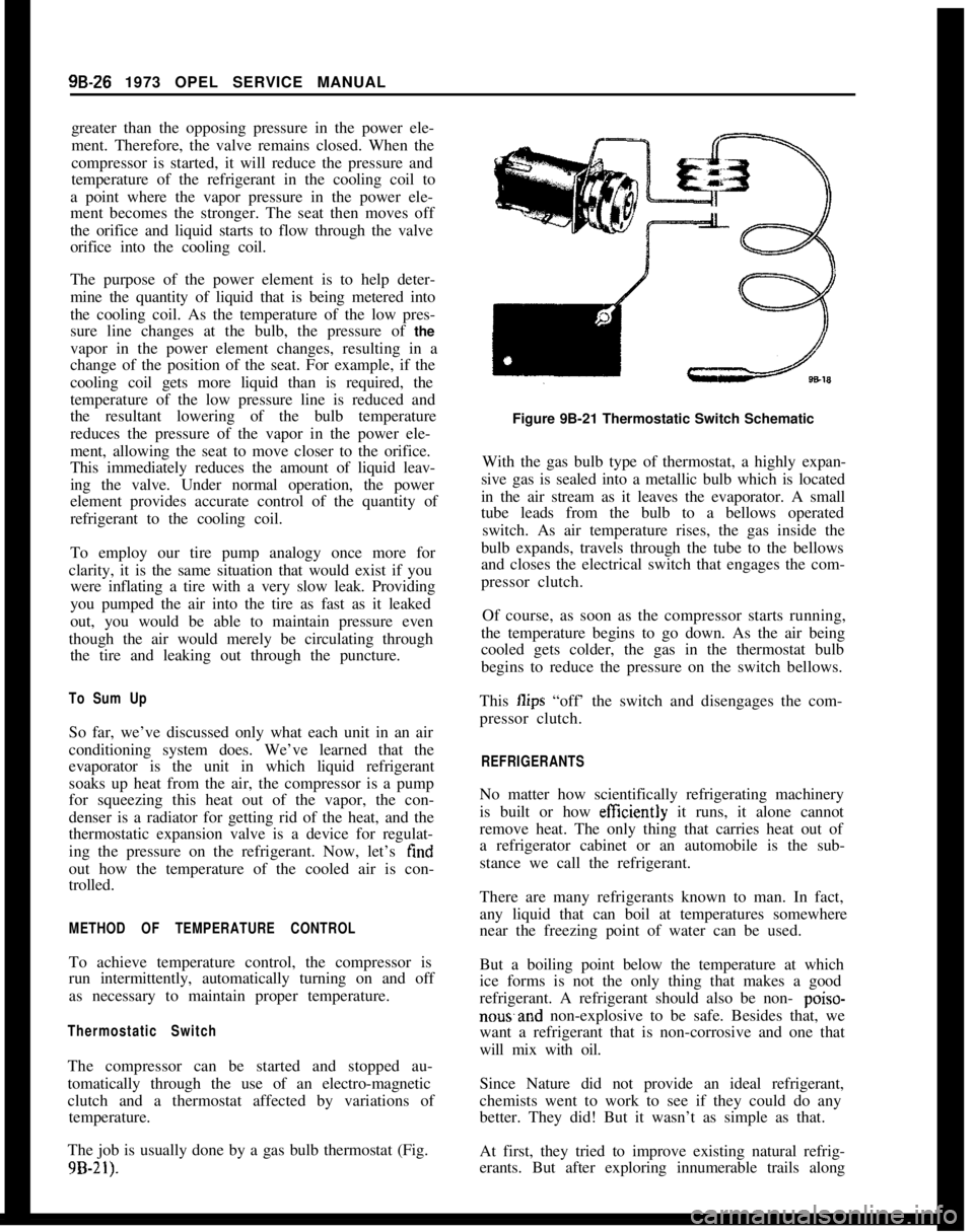
The job is usually done by a gas bulb thermostat (Fig.
9B-21).
Figure 9B-21 Thermostatic Switch Schematic
With the gas bulb type of thermostat, a highly expan-
sive gas is sealed into a metallic bulb which is located
in the air stream as it leaves the evaporator. A small
tube leads from the bulb to a bellows operated switch. As air temperature rises, the gas inside the
bulb expands, travels through the tube to the bellows
and closes the electrical switch that engages the com-
pressor clutch.
Of course, as soon as the compressor starts running,
the temperature begins to go down. As the air being
cooled gets colder, the gas in the thermostat bulb
begins to reduce the pressure on the switch bellows.
This
Ilips “off’ the switch and disengages the com-
pressor clutch.
REFRIGERANTS
No matter how scientifically refrigerating machinery
is built or how
efftciently it runs, it alone cannot
remove heat. The only thing that carries heat out of
a refrigerator cabinet or an automobile is the sub-
stance we call the refrigerant.
There are many refrigerants known to man. In fact,
any liquid that can boil at temperatures somewhere
near the freezing point of water can be used.
But a boiling point below the temperature at which
ice forms is not the only thing that makes a good
refrigerant. A refrigerant should also be non-
poiso-
nowand non-explosive to be safe. Besides that, we
want a refrigerant that is non-corrosive and one that
will mix with oil.
Since Nature did not provide an ideal refrigerant,
chemists went to work to see if they could do any
better. They did! But it wasn’t as simple as that.
At first, they tried to improve existing natural refrig-
erants. But after exploring innumerable trails along
Page 622 of 625

Subject
Page NumbelSubjectPage Number4.Speed Manual I..
Clutch
Detent Cable Adjustment
:Differential
Directional Signal Switch
Repair Opel 1900 & Manta
Repair GT
:Disassembly of
4.Speed Manual Transmission
DistributorFunction of Valves and Hydraulic Control Units
Opel
3.Speed Automatic.................
74-21
Fuse Chart..............................lG-56
Fusible Link.............................
lA-8Specifications.
Point Replacement..
..,78-127A-
17c-9148-73E-393E-4878.23
1C-26
1 c-20
GEGas Tank See Fuel Tank
General Specifications
Engine...............................6A-28
Opel 3.Speed Automatic
.................7C-134
Transmission, Manual.,
..................78-33
Clutch...............................7A-7
Body................................ZA-4
Governor Drive Gear
Opel
3.Speed Automatic.................7C-103
Grille
Opel 1900 & Manta.....................8A-7
GT..................................8A-6 Electrically Heated Rear Window
Engine
General Description
Cooling System
Lubrication System
Trouble Diagnosis
Exhaust Manifold
Exhaust System
Removal and Installation
External Oil Leaks,
Opel 3 Speed Automatic
FFast Idle Adjustment
..................
Filter-Engine Oil
......................
Fluid Checking Procedure Transmission
Opel 3Speed Automatic.............
Frame-Opel 1900 & Manta.............
Frame
GT-Opel......................
SWVOOpel Xipeed Automatic...........
Front Suspension
Opel1900&Manta.................
GT..............................
Front Wheel Alignment................
Front Wheel Bearing Adjustment
All Series.........................
Fuel Gauge
Trouble Diagnosis
Opell$OO&Manta...............
GT............................
Fuel Pump Operation..................
Fuel System
Fuel Tank (Opel 1900 & Manta)
.......
Fuel Lines (Opel 1900 & Manta)
.......
Fuel Tank
(GT)....................
Fuel Gauge Tank Unit
(GT)...........
Fuel Lines
(GT)....................
Fuel Tank Removal and Installation....
Cleaning Tank.....................
lH-576A-268-326A-46A-66A-126D-427C-816E-51
oc-77C~Bl2B-826-77c-1003A-23A-23C-223A-4
HHazard Warning Flasher
....................lG-55
Headlamp Aiming
.........................1 F-46
Headlamp Switch
Opel 190.0 & Manta
.....................1 F-46
Headlamp Mechanism GT
..................8A-2
Heater System Opel 1900 &Manta
Trouble Diagnosis
......................9A-11
Description and Operation
................9A-10
Adjustments and Minor Service............9A-12
Removal and Installation
.................9A-12
Specifications..........................$A-16
Heater System GT
Trouble Diagnosis
......................9A-4
Description and Operation
................9A-2
Adjustments and Minor Service
............9A-4
Removal and Installation.................9A-5
Specifications..........................$A-9Horn
Operation.............................lG-54
Hydraulic Operation
Opel
3.Speed Automatic.................7C-64
IIdentification Number Vehicle...............
OA-1ldle.Adjustment
..........................6E-51
Inflation Pressures, Tires.
...................36-62
Ignition Coil
Specifications.
.........................
lC-26Identification, Engine
......................
OA-1Ignition System
Timing...............................
lC-20Instrument Panel Parts Removal
Page 624 of 625

SubjectPage Number1
Throttle Linkage Adjustment........,:.......6E-51
Timing Chain Cover.......................6A-23
Timing Chain and Sprocket.........
':.......6A-23
Tires...................................36-55
Inflation.....................
.;.......3G-62
Rotation.............................36-57
Sizes.........................
........3G-62
Track Rod..............................3F-53
Transmission Oil Pan
Automatic Transmission.................7C-99
Transmission Reassembly
4 Speed Manual. 1.9.....................76-28Tranmission Removal and Installation
4 Speed Manual
Removal...........................7B-22
Installation.........................76-22
Auto&tic............................7c-94Tune’Up Procedure........................66-65
Torque Specifications. Engine...............6A-27
Turn Signal See Directional Signal
Universal Joints..........................4A-3Subject
VPage Number
Vacuum Modulator..7C-101
Valve Body Transmlssmn7C.99
Valve and Seat Reconditioning Engine6A-12
WWater Pump Engine1.9L Engine
Wheels
Wheel Alignment
Whee! Bearing, Adjustment,
Windshield Wiper and Washer:
Trouble Diagnosis:Description and Operation
Removal and Installation
Specifications
Wiring Diagrams Complete
Opel 1900 ._.
Manta
GT
1 E-37
1 E-37
1 E-38
1 E-43
1 J-l 03
1 J-l 05lJ-10768-3436-553C-223A-4