clock OPEL GT-R 1973 Owner's Guide
[x] Cancel search | Manufacturer: OPEL, Model Year: 1973, Model line: GT-R, Model: OPEL GT-R 1973Pages: 625, PDF Size: 17.22 MB
Page 420 of 625
AUTOMATIC TRANSMISSION7c- 59
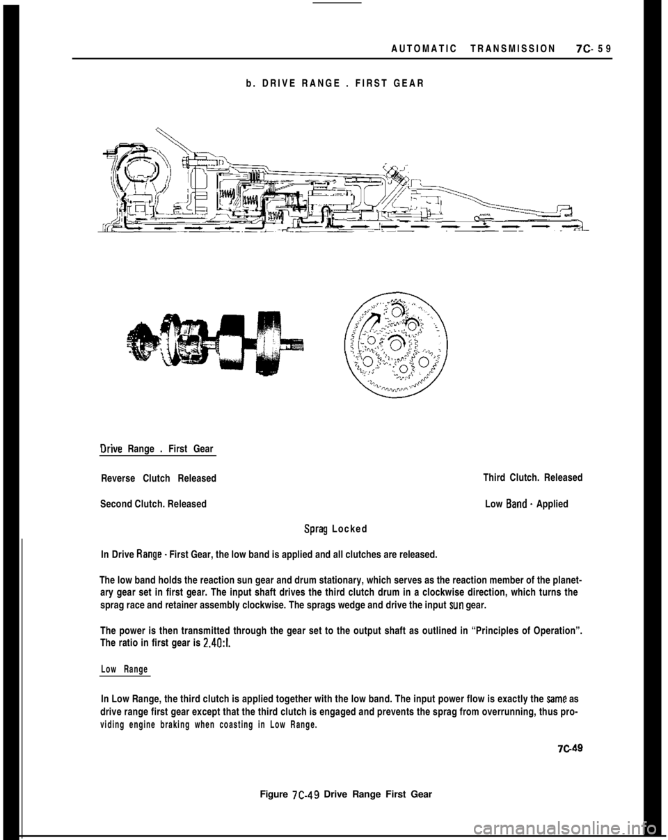
b. DRIVE RANGE . FIRST GEAROrive Range . First Gear
Reverse Clutch Released
Second Clutch. Released
Sprag Locked
In Drive Range. First Gear, the low band is applied and all clutches are released.
Figure 7C-49 Drive Range First GearThird Clutch. Released
Low Band. Applied
The low band holds the reaction sun gear and drum stationary, which serves as the reaction member of the planet-
ary gear set in first gear. The input shaft drives the third clutch drum in a clockwise direction, which turns the
sprag race and retainer assembly clockwise. The sprags wedge and drive the input
sun gear.
The power is then transmitted through the gear set to the output shaft as outlined in “Principles of Operation”.
The ratio in first gear is 2.4O:l.
Low RangeIn Low Range, the third clutch is applied together with the low band. The input power flow is exactly the
Same as
drive range first gear except that the third clutch is engaged and prevents the sprag from overrunning, thus pro-
viding engine braking when coasting in Low Range.
7c49
Page 421 of 625

7C- 601973 OPEL SERVICE MANUAL
c. DRIVE RANGE. SECONO GEAROrive Range . Second Gear
Reverse Clutch - Released
Second Clutch -Applied
Sprag
- Overrunning
In Drive Range. Second Gear, the low band and second clutch are applied.Third Clutch
- Released
Low Band -Applied
The input shaft drives the third clutch drum and the second clutch composition plates. When the second clutch
piston is applied, the rotating second clutch composition plates are locked
w the second clutch steel plates. Since
the second clutch drum is now rotating in a clockwise direction, the ring gear is driven clockwise. As described in
“Principles of Operation”, the carrier is driven in a clockwise direction. The long planet pinions also drive the
short planet pinions, which drive the input sun gear clockwise, causing the sprag assembly to overrun. The ratio
is 1.48:1.
second Range
In Second Range, the Power flow is exactly the seme as drive range - second gear.7c50
Figure
7C-50 Drive Range - Second Gear
Page 478 of 625

AUTOMATIC TRANSMISSION 7C-117WIRE CRIMPED
INTO COPPERTUBING
Figure 7C-178
19. Inspect condition of the third clutch composition
and steel plates. Do not diagnose a composition
drive plate by color,A. Dry composition plates with compressed air and
inspect the composition surface for:
1. Pitting and flaking
2. Wear
3. Glazing
4. Cracking
5. Charring
6. Chips or metal particles imbedded in lining
If a composition drive plate exhibits any of the above
conditions, replacement is required.
B. Wipe steel plates dry and check for heat discolora-
tion. If the surface is smooth and an even color smear
is indicated, the plates should be reused. If severe
heat spot discoloration or surface
scutXng is in-
dicated, the plates must be replaced.
20. Install third clutch plates into third clutch drum
beginning with a steel plate, composition plate, steel
plate, composition plate, etc. Use a liberal amount of
transmission fluid.
21. Inspect thrust washer and needle thrust bearing
for damage. Replace if necessary.
22. Install thrust washer and bearing onto input
shaft. Secure with petroleum jelly (unmedicated).23. Inspect sprag assembly for wear, damage orsprags that freely fall out of cage. Inspect input sun
gear for chipped or nicked teeth or abnormal wear.
Replace part if necessary.
24. Install sprag onto third clutch hub with groove
on sprag cage outer diameter toward input sun gear.
See Figure
7C-179.Figure 7C-179
25. Install sprag race and retainer assembly over
sprag assembly. Holding input sun gear with left
hand, sprag race and retainer assembly should “lock
up” when turned with right hand in a clockwise
direction and should rotate freely when turned coun-
terclockwise. See Figure
7C-180.Figure 7C-180
Page 550 of 625
REFRIGERANT COMPONENTS ALL MODELS9s. 41
BIower Operating Normal Check for the following:Restriction or leakage in air ducts, A/C outlets not
opening.2. Do not carry cylinder in passenger compartment
of car.3. Do not subject cylinder to high temperatures.
MAINTENANCE AND ADJUSTMENTS4. Do not weld or steam clean on or near cylinder.
5. Do not fill cylinder completely.
GENERAL SERVICE INFORMATION AND SAFETY
PRECAUTIONS6. Do not discharge vapor into area where flame is
exposed or directly into engine air intake.
General InformationAll subassemblies are shipped sealed and dehy-
drated. They are to remain sealed until just prior to
making connections, and should be at room tempera-
ture before uncapping. This prevents condensation of
moisture from air that enters the system.
All precautions should be taken to prevent damage
to fittings or connections. Even minute damage to a
connection could cause it to leak. Any fittings with
grease or dirt on them should be wiped clean with a
cloth dipped in alcohol.
Do not clean fitting or hoses with solvents because
they are contaminants. If dirt, grease or moisture
gets inside the pipes or hoses and cannot be removed,the pipe or hose is to be replaced. Use a small amount
of clean refrigeration oil on all tube and hose con-
necting joints, and lubricate the
“0” ring gasket with
this oil before assembling the joint. The oil will help
in effectitig a leak-proofjoint and assist the
“0” ring
to slip into the proper location without being cut or
damaged. Always use new
“0” rings.
When tightening joints, use a second wrench to hold
the stationary part of the connection to prevent
twisting and to prevent hose kinking. Kinked hoses
are apt to transmit noise and vibration. Tighten all
connections in accordance with recommended
torques (see Division VI, Specifications).7. Do not expose eyes to liquid
- WEAR SAFETY
GOGGLES whenever discharging, charging or leak
testing system.
CHARGING AND DISCHARGING SYSTEMRemoval of any part in the refrigerant circuit will
require discharging of the entire system.
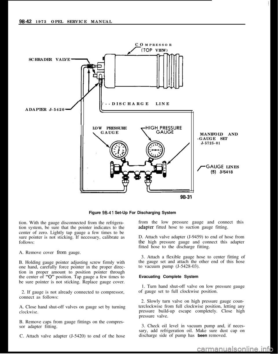
Discharging the System1. Remove caps from gauge fittings on the compres-
sor adapter fitting on the compressor.
2. With both valves on manifold gauge set (J-5725-
04) closed (clockwise), attach manifold to the com-
pressor adapter fitting on the compressor, using
J-5420 valve adapter at suction gauge fitting and
J-9459 valve adapter at discharge gauge fitting. See
Figure
9B-41.3. Fully open high pressure valve on manifold gauge
set to allow escape of refrigerant from system
through the manifold gauge set and out the center
fitting and hose. (Place end of hose in clean container
to collect oil loss due to rapid discharge of system).
4. When hissing ceases, indicating all refrigerant
has escaped, close high pressure valve on manifold
gauge set by turning valve clockwise.
Do not connect receiver-dehydrator assembly until
all other connections have been made. This is neces-
sary to itisure maximum moisture removal from sys-
tem.It is important that air conditioning hoses do not rest
on or contact body sheet metal except where neces-
sary. Because of the high frequency at which the
compressor operates, the passenger compartment is
susceptible to transfer of noise.
Evacuating the SystemWhen the refrigeration system is depressurized and
opened for service, some air will enter the lines, re-
gardless of how quickly openings are capped. In
or-der to remove this air and as much as possible of the
moisture it contains, the complete system must be
evacuated. Evacuating is merely the process of
removing all air from the system, thereby creating a
vacuum in the system.
Safety PiecautionsThe following safety precautions should always be
followed~,when servicing refrigerant charged compo-nents:Under no circumstances should alcohol be used in
the system in an attempt to remove moisture,
regard-less of the successful use of alcohol in other refrigera-
tion systems.
Preparations for Evacuating Complete System
1. Do not leave Refrigerant-12 cylinder uncapped.
1. Check the low pressure gauge for proper calibra-
Page 551 of 625
98-42 1973 OPEL SERVICE MANUAL
SCHRADER VALVE
ADAPTER J-54201COMPRESSOR(TOP VIEW)[/--DISCHARGE LINE
ILOW PRESSURE\ GAUGE
MANIFOLD AND
-GAUGE SET
J-5725-01
rGAUGE LINES
(5) J-541899-31
Figure 98.41 Set-Up For Discharging System
tion. With the gauge disconnected from the refrigera-
tion system, be sure that the pointer indicates to the
center of zero. Lightly tap gauge a few times to be
sure pointer is not sticking. If necessary, calibrate as
follows:
A. Remove cover from gauge.
B. Holding gauge pointer adjusting screw firmly with
one hand, carefully force pointer in the proper direc-
tion in proper amount to position pointer through
the center of
“0” position. Tap gauge a few times to
be sure pointer is not sticking. Replace gauge cover.
2. If gauge is not already connected to compressor,
connect as follows:
A. Close hand shut-off valves on gauge set by turning
clockwise.B. Remove caps from gauge fittings on the compres-
sor adapter fitting.
C. Attach valve adapter (J-5420) to end of the hosefrom the low pressure gauge and connect thisadapl:er fitted hose to suction gauge fitting.
D. Attach valve adapter (J-9459) to end of hose from
the high pressure gauge and connect this adapter
fitted hose to the discharge fitting.
3. Attach a flexible gauge hose to center fitting of
the gauge set and attach the other end of this hose
to vacuum pump (J-5428-03).
Evacuating Complete System
1. Turn hand shut-off valve on low pressure gauge
of gauge set to full clockwise position.
2. Slowly turn valve on high pressure gauge coun-
terclockwise from full clockwise position, letting any
pressure build-up escape completely. Close high
pressure valve.
3. Check oil level in vacuum pump and, if neces-
sary, add refrigeration oil. Make sure dust cap on
discharge side of pump has been removed.
Page 552 of 625
REFRIGERANT COMPONENTS ALL MODELS9B- 43
4. Start the vacuum pump and slowly open low and
high pressure sides of manifold gauge set to avoid
forcing oil out of refrigeration system and pump,
Pressure is now being reduced on both sides of the
refrigeration system. If oil is blown from the vacuum
pump, it should be refilled to the proper level.
5. Observe low pressure gauge and operate vacuum
pump until gauge shows 28-29 inches vacuum. In all
evacuating procedures, specifications of 28-29 inchesof vacuum is used. This evacuation can only be at-
tained at or near sea level.
For each 1000 feet above sea level where this operat-ion is being-performed, the specification should be
lowered by one inch of mercury vacuum. At 5000
feet elevation, only 23 inches to 24 inches of vacuum
can normally be obtained.
If vacuum cannot be pulled to the minimum specifi-
cation for the respective altitude, it indicates a leak
in the system or gauge connections or a defective
vacuum pump. In this case, it will be necessary to
check for leaks as described under “Leak Testing
Refrigerant System”.
When specified vacuum level (28-29 inches at sea
level) is obtained, continue to run vacuum pump for
ten (10) ‘additional minutes. During these ten (10)
minutes:
A. Prepare for charging the system. If using a charg-
ing station, till charging cylinder. If using manifold
gauge set, make all preparations for charging system
as described under “Disposable Can Method” or
“Refrigerant Drum Method”.
B. Measure oil loss collected as a result of rapid
discharge.
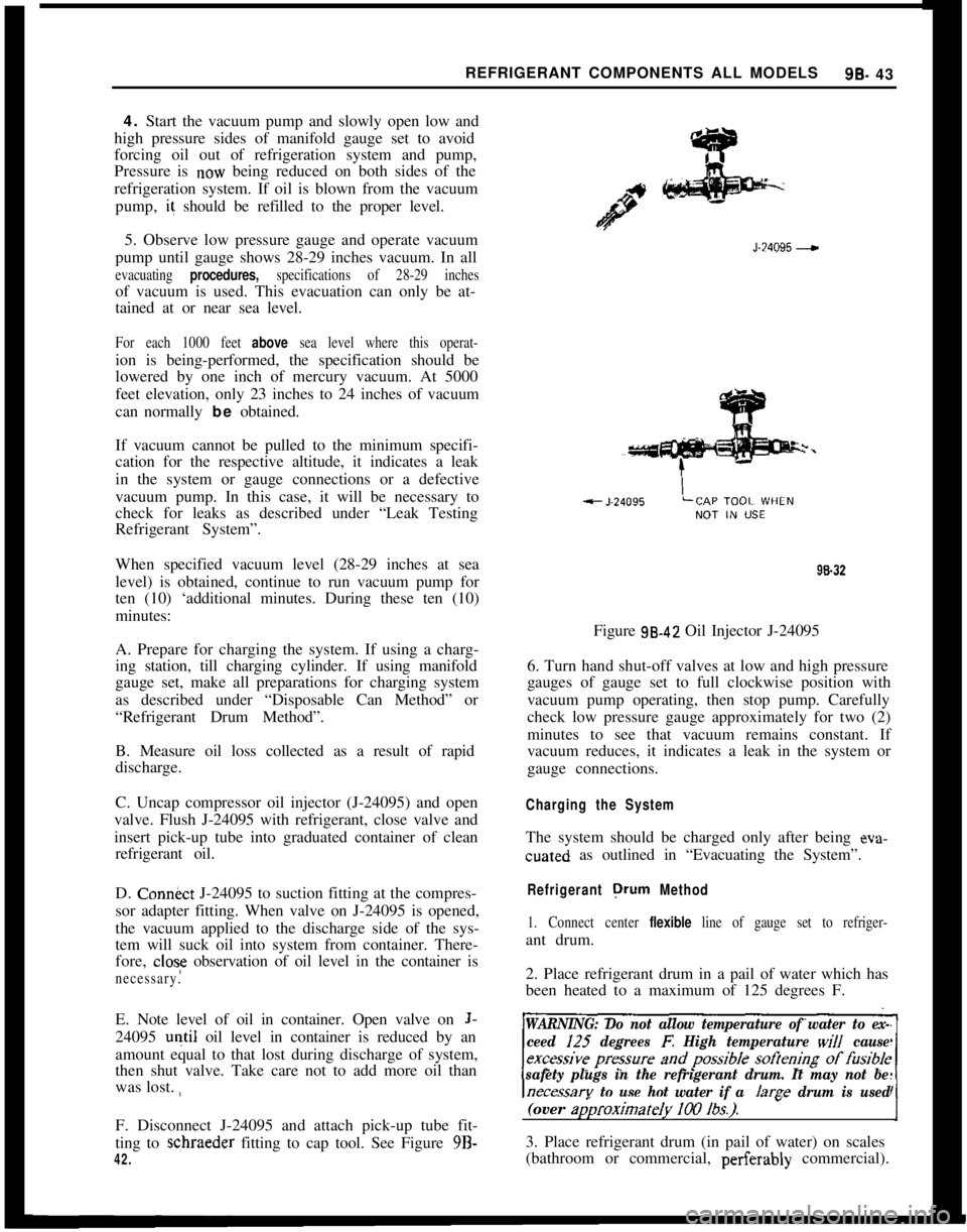
C. Uncap compressor oil injector (J-24095) and open
valve. Flush J-24095 with refrigerant, close valve and
insert pick-up tube into graduated container of clean
refrigerant oil.
D. Con&ct J-24095 to suction fitting at the compres-
sor adapter fitting. When valve on J-24095 is opened,
the vacuum applied to the discharge side of the sys-
tem will suck oil into system from container. There-
fore,
close observation of oil level in the container is
necessary.E. Note level of oil in container. Open valve on
J-24095
u+il oil level in container is reduced by an
amount equal to that lost during discharge of system,
then shut valve. Take care not to add more oil than
was lost. ,,
F. Disconnect J-24095 and attach pick-up tube fit-
ting to schraeder fitting to cap tool. See Figure 9B-
42.J-24095
-98.32
Figure 98.42 Oil Injector J-24095
6. Turn hand shut-off valves at low and high pressure
gauges of gauge set to full clockwise position with
vacuum pump operating, then stop pump. Carefully
check low pressure gauge approximately for two (2)
minutes to see that vacuum remains constant. If
vacuum reduces, it indicates a leak in the system or
gauge connections.
Charging the SystemThe system should be charged only after being eva-cuated as outlined in “Evacuating the System”.
Refrigerant orurn Method
1. Connect center flexible line of gauge set to refriger-ant drum.
2. Place refrigerant drum in a pail of water which has
been heated to a maximum of 125 degrees F.
WARNING: Do not allow temperature of water to ex-
ceed I25
degrees E High temperature will cause
safety plugs in the refrigerant drum. It may not be
necessarv to use hot water if a /arae drum is used(over
ap)roximateIy 100 lbs.).-I3. Place refrigerant drum (in pail of water) on scales
(bathroom or commercial, perferably commercial).
Page 553 of 625
9B-44 1973 OPEL SERVICE MANUAL
Do not turn refrigerant drum upside down, as this
would allow liquid refrigerant to enter compressor
which may cause damage.
4. If line at center gauge fitting has not been purged
of air, loosen line at center fitting on gauge set and
crack valve on refrigerant drum to blow air from
line. Retighten line at center fitting and record exact
weight of refrigerant tank in water on the scales.
5. Open valve on refrigerant drum and both valves
on gauge set to allow refrigerant to flow into system.
Continue charging until the scales show that 2
Ibs.Opel 1900
- Manta and 2 l/4 lbs. GT, of refrigerant
have been transferred from refrigerant drum to sys-
tem.If full charge cannot be obtained, close both valves
on gauge set, start engine, and set temperature con-
trol knob to full cold position with blower in Max Hi.
Open low pressure valve on gauge set slowly and
leave open until full charge is added.
WARNING: Observe high pressure gauge while charg-
ing with compressor running. Shut
offengine ifpres-
sure exceeds 250 psi. A large fan placed in front
ol
the car wi// help reduce excessively high head pres-6. Close both valves on gauge set (high pressure valve
will already be closed if charging was completed by
running compressor) and close valve on refrigerant
drum.
If the engine was used to complete the charge into
the system, close valve on refrigerant drum to permit
compressor to draw any refrigerant left in the line
from the drum to the center fitting of the gauge set,
then close the low pressure valve on the gauge set.
7. Operate engine at 2000 RPM with temperature
control knob at full cold, blower speed in Max Hi.
After ten minutes of operation, observe appearance
of refrigerant in receiver-dehydrator. If bubbles are
observed, open low pressure gauge valve and valve
on refrigerant drum to allow more refrigerant to en-
ter system. Close valve when receiver-dehydrator
clears
up.If an air inlet temperature is below 70 degrees F.
when this check is made, bubbles may appear, even
though the proper amount of refrigerant is in the
system. Air inlet temperature must be 70 degrees F.
or above to make an accurate check.
8. When refrigerant has been installed, continue to
operate system and test for proper operation as ou-
tlined under “Operational Test”.
9. When satisfied that air conditioning system is op-
erating properly, stop engine, remove gauge set and
replace protective caps on compressor fittings.10. Using leak detector, check complete system for
leaks.Disposable Can Method
After having
depress&ed, repaired (if necessary)
and evacuated the refrigerant system, the system
may be charged as follows using refrigerant in dis-
posable cans:
1. Obtain three (3) 1
lb. cans or one 12 lb. can of
refrigerant.
2. If using 1 lb. cans, mount two (2) cans in J-6272-
02 (Multi-opener) or attach J-6271 (single-can
opener valve) on one can. If using the 12
lb. disposa-
ble can, attach J-23390 (disposable can control valve)
on can.WARNING: Make sure outlet valve on opener is
closed (clockwise) before installing opener.A. If the J-6272-02 multi-opener is used, raise lock-
ing lever, position three (3) cans of refrigerant and
force locking lever down to secure cans and at same
time puncture top of can to make it ready for charg-
ing.
B. If the J-6271 valve is used, back off the valve from
the can top retainer, slip the valve onto the can and
turn the valve into retainer until tight. DO NOT
open outlet valve during this operation, as turning
the valve into the retainer punctures top of can to
make it ready for charging.
3. Connect center flexible line of gauge set to fitting
on a can opener valve. If the line at center gauge
fitting has not been purged of air, loosen line at
center fitting on gauge set and “crack” valve at can
opener (for a second or two) to force air from the
line. Retighten line at center fitting.
4. Open valve at refrigerant source and at low and
high pressure valves on manifold gauge set. Leave
valve open at refrigerant source until all refrigerant
(when using 1 lb. can) has ‘entered the refrigeration
system or system is fully charged. Close valve on can.
A. If the system is charged using
1 lb. cans and the
J- 627 1 valve, disconnect valve from can. Leave valve
closed to flexible line to the center fitting of the
manifold gauge set. Install valve on a new and full
disposable can of refrigerant.
Page 554 of 625
REFRIGERANT COMPONENTS ALL MODELS9t3- 45
B. If system is charged using J-6272-02, close the
valve of opener after all cans are empty. Release the locking lever and discard the three (3) empty cans.
If this tool will be used to complete the charge with
additional cans to provide the required refrigerant
charge, leave the empty cans in position, locate one
full can and lock the lever into place. These empty
cans balance the assembly and prevent the loss of
refrigerant through the open “series” passage. Align
the pierced hole in the empty can with the punch in
the cover of the tool.
If the J-6271 valve for single cans is available, com-
plete charging as explained in 4a above.
5. Close high side valve on manifold gauge set,
WARNING: Prior to starting up engine, the high side
valve on the charging manifold must be closed due
to excessive pressure
bui/d-up which can result in
bursting of the container(s) causing serious injury. If
you are inexperienced in the use of this procedure, seek professional assistance.
6. Operate engine at 2000 RPM with temperature
control knob at full cold position and blower speed
on Max Hi. If air inlet temperature at the condenser
is below 70 degrees F. when this check is made,
bubbles may appear, even though the proper amount
of refrigerant is in the system. Air inlet temperature
must be 70 degrees F. or above to make an accurate
check.
7. When refrigerant has been installed, continue to
operate system and test for proper operation as ou-
tlined
under “Operational Test”.
8. When satisfied that the air conditioning system
is operating properly, stop engine, remove gauge set
and replace protective caps on suction and discharge
fittings.
from thegauge fitting to prevent damage-or injury to
personnel.
9. Using a leak detector, check complete system for
leaks.
Charging Station Method
INSTALLING J-8393-02
-
1. Be ceitain compressor hand shut-off valves to
gauge fittings are closed (counterclockwise).
2. Be certain all valves on charging station are
closed.
3. Connect high pressure gauge line to compressor
high pressure gauge fitting.
4. Turn high pressure hand shut-off valve one turn
clockwise, and high pressure control one turn coun-
terclockwise (open). Crack open low pressure con-
trol and allow refrigerant gas to hiss from low
pressure gauge line for three seconds, then connect
low pressure gauge line to low pressure gauge fitting
on compressor adapter fitting. (Place J-9459 adapter
on hose, then attach adapter to gauge fitting.)
FILLING CHARGING CYLINDER
1. Open Control valve on refrigerant container.
2. Open valve on bottom of charging cylinder, al-
lowing refrigerant to enter cylinder.
3. Bleed charging cylinder to valve (behind control
panel) only as required to allow refrigerant to enter
cylinder. When refrigerant reaches desired charge
level, close valve at bottom of charging cylinder and
be certain cylinder bleed valve is closed securely.
While filling the cylinder, it will be necessary to close
the bleed valve periodically to allow boiling to sub-
side so that refrigerant level in the charging cylinder
can be accurately read.
CHARGING THE SYSTEM USING J-8393-02
1. With charging station connected, as previously
described, remove low pressure gauge line at com-
pressor adapter fitting.
2. Crack open high and low pressure control valves
on station and allow refrigerant gas to purge from
system. Purge slowly enough so, that oil does not
escape from system along with refrigerant.
3. When refrigerant flow nearly stops, connect low
pressure gauge line to
compress& adapter fitting.
4. Turn on vacuum pump and open vacuum control
valve.
5. With system purged as
abovk, run pump until
26-28 inches of vacuum is obtained Continue to run
pump for 15 minutes after the system reaches 26-28
inches vacuum.
In all evacuating procedures, the specification of
26.
28 inches of mercury vacuum is used. These figures
are only attainable at or near sea level. For each 1000
feet above sea level where this operation is being
performed, the specifications should be lowered by 1
inch. For example, at 5000 feet elevation, only 21 to
23 inches vacuum can normally be obtained.
6. If 26-28 inches vacuum (corrected to sea level)
cannot be obtained, close vacuum: control valve and
Page 555 of 625
98-46 1973 OPEL SERVICE MANUAL
shut off vacuum pump. Open refrigerant control
valve and allow some refrigerant to enter system.
Locate and repair all leaks.
7. After evacuating for 15 minutes, add l/2 lb. of
refrigerant to system. Purge this
l/2 lb. and reevacu-
ate for 15 minutes. This second evacuation is to be
certain that as much contamination is removed from
the system as possible.
8. Only after evacuating as above, system is ready
for charging. Note reading on sight glass of charging
cylinder. If it does not contain a sufficient amount
for a full charge, till to proper level.
9. Close low pressure valve on charging station.
Fully open station refrigerant control valve and al-
low all liquid refrigerant to enter system. When full
charge of refrigerant has entered system, turn off
refrigerant control valve and close both hand shut-
off valves.
10. If full charge of refrigerant will not enter system,
close high pressure control and refrigerant control
valves. Start engine and run at low idle with com-
pressor operating. Crack refrigerant control valve
and low pressure control on station. Watch low side
gauge and keep gauge below 50 psi by regulating
refrigerant control valve. Closing valve will lower
pressure. This is to prevent liquid refrigerant from
reaching the compressor while the compressor is op-
erating. When required charge has entered system,
close refrigerant control valve and close low pressure
control.
11. System is now charged and should be perform-
ance- tested before removing gauges.
Adding Refrigerant
The following procedure should be used in adding
small amounts of refrigerant that may have been lost
by leaks or while opening system for servicing the
compressor. Before adding refrigerent to replace that
lost by leaks, check for evidence of oil loss and add
oil if necessary.
This procedure will only apply if the air inlet temper-
ature is above 70 degrees F. at the condenser.
1. Remove caps from compressor gauge fittings.
Attach gauge set to gauge fittings, making sure
adapter (J- 5420) is between low pressure gauge hose
and suction gauge fitting, and J-9459 is between high
pressure gauge hose and discharge gauge fitting.
2. Start engine, turn air conditioning temperature
control knob to full cold position, blower switch to
Max Hi. Operate for ten
(IO) minutes at 2000 RPM
to stabilize system.
3. Observe the refrigerant through the sight glasscover of receiver-dehydrator with the system operat-
ing,
IO see if there are any bubbles evident.
a. If no bubbles are evident, then bleed system slowly
through the discharge valve until bubbles appear in
the receiver-dehydrator. Add 1 lb. of refrigerant as
explained under “Charging the
ISystem”.b. If bubbles are visible in the receiver-dehydrator
with the temperature control krlob in the full cold
position and the blower at MAX speed, it indicates
a partial or complete plug in a line, a shortage of
refrigerant, or both. Correct condition. Add refriger-
ant
u~ntil the sight glass clears, then add another 1 lb.
of refrigerant.
4. Attach flexible hose from center fitting of gauge
set loosely to refrigerant drum or on disposable can
valvxs. Open high and low pressure valves on the
gauge set slightly to purge pressure gauge lines of air.
Tighten fitting of refrigerant drum or can when satis-
fied ihat all air has been removed from gauge lines.
Close (clockwise) both hand shut-off valves or gauge
set.5. Partially charge system.
REFRIGERANT DRUM METHOD:
A. Place pail containing hot water that does not have
a temperature exceeding 125 degrees F. on scales,
place refrigerant drum in pa” containing water, note
weig,ht and only open low pressure valve on gauge
set.B. Start engine, turn temperature control knob to full
cold position and place blower switch in Max Hi.
Operate engine for 10 minutes at 2000 RPM to sta-
bilize system.
C. With compressor operating, slowly open valve on
refrigerant drum and allow refrigerant to flow into
system (through manifold gauge set) until liquid in-
dicator clears up and immediately shut off valve ai
gauge set or on refrigerant drum. Check weight of
refrigerant drum and pail of water. Then slowly open
valve on gauge set (or refrigerant drum) and add one
more lb. of refrigerant. Note total amount of refriger-
ant added.
DISPOSABLE CAN METHOD:
A. Make sure the outlet valve on the J-6271 valve is
fully clockwise and attach the J-6271 to a 1 lb. can
of refrigerant by backing off the valve from the top
of the retainer, slipping the valve onto the can and
turning the valve into the retainer until tight. DO
NOT accidentally open outlet valve during this oper-
ation, as turning the valve into the retainer punctures
the top of the can to make it ready for charging.
.
Page 573 of 625

9B-64 1973 OPEL SERVICE MANUAL
4. Using No. 21 Truarc pliers (J-5403) take out
retainer ring from hub of clutch drive plate (see Fig-
ure 9B-106). Lift our spacer.
Figure 95.106 Removing
or Installing Retainer Ring inClutch Drive Plate5. If compressor has an absorbent sleeve in the neck,
pry out the sleeve retainer and remove the sleeve.
Remove the seal seat retainer ring, using No. 21
Truarc pliers, Tool J-5403, (see Figure
9B-107).
SEAL SEATFigure 98.107 Removing or Installing Shaft Seal Seat
Retaining Ring6. Thoroughly clean the area inside the compressor
neck surrounding the shaft, the
ezxposed portion of
the seal seat and the shaft itself of any dirt or foreign
material. This is absolutely necessary to prevent any
such material from getting into
t:he compressor.
7. Remove the seal seat (see Figure 9B-108) using
Tool J-23128. Insert Tool
J-2312E; into seal seat and
tighten, using a twisting motion remove the seal seat.96-82
Figure SE-108 Removing or Installing Ceramic Shaft
Seal seat
8. Remove the seal assembly, using Tool J-9392.
Press tool downward on seal while twisting it clock-
wise to engage the tabs of the seal assembly. Gently
but firmly, pull tool straight out (see Figure
9B-109).9. Remove the seal seat
“0” ring, using Tool J-9553
(see Figure
9B-110).10. Recheck the inside of the compressor neck and
the shaft. Be sure these areas are perfectly clean
before installing new parts.
Reassembly
1. Coat the new seal seat
“0” ring with clean refrig-
eration oil and install it in its groove in the compres-
sor neck. Tool J-21508 may be used to accomplish
this. (See Figure
9B;,lll)2. Coat the
“0” ring and seal face of the new seal
assembly with clean refrigeration oil. Carefully
mount the seal assembly to Tool J-9392 by engaging
the tabs of the seal with the tangs of the tool.
3. Place seal protector, Tool J-22974, over end of
shaft and carefully slide the new seal assembly onto
the shaft. Gently twist the tool clockwise while push-
ing the seal assembly down the shaft until the seal