clock OPEL GT-R 1973 Owner's Manual
[x] Cancel search | Manufacturer: OPEL, Model Year: 1973, Model line: GT-R, Model: OPEL GT-R 1973Pages: 625, PDF Size: 17.22 MB
Page 299 of 625
6A- 8 1973 OPEL SERVICE MANUAL
Actual adjustment is made by backing off adjusting
nut at the rocker arm until clearance exists between the valve stem, rocker arm, and lifter. Then slowly
tighten adjusting nut until clearance is eliminated.
When clearance is eliminated, turn adjusting nut one
full turn (clockwise). This positions the hydraulic
piston of the hydraulic lifter mid-point in its total
available travel, and no further adjustment is re-
quired.
MAJOR REPAIR
ENGINE ASSEMBLY REMOVAL AND
INSTALLATION
Removal (Opel 1900 and Manta)’
The engine assembly on the Opel 1900 and Manta
can be removed together with the transmission
through the top of the engine compartment.
1. Remove hood (scribe hood hinge to hood mount-
ing location).
2. Disconnect battery negative cable.
3. Drain coolant at lower radiator hose.
4. Remove upper and lower radiator hoses.
5. Remove radiator and fan
shrbud.
6. Disconnect heater hoses.
7. Disconnect brake booster
vacuum hose.
8. Remove air cleaner.
9. Disconnect electrical connections and accelerator
linkage. 10. Remove console.
11. Remove shift lever boot, plate, and shift lever.
12. Raise car on hoist.
13. Disconnect fuel line at pump.
14. Remove front stone shield.
15. Disconnect speedo-cable, back-up light switch,
and clutch cable.
16. Remove drive shaft. I
17. Disconnect exhaust pipe
ar$l bell housing sup-
port.
18. Disconnect transmission support. See Figure
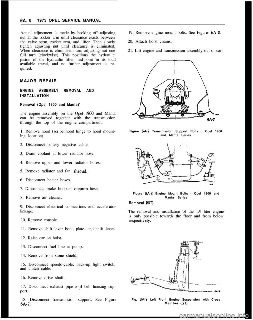
6A-7. 19. Remove engine mount bolts. See Figure
6A-8.
20. Attach hoist chains.
21. Lift engine and transmission assembly out of car.
Figure 6A-7 Transmission Support Bolts . Opel 1900
and Manta Series
Figure
6A-B Engine Mount Bolts - Opel 1900 and
Manta Series
Removal (GT)
The removal and installation of the 1.9 liter engine is only possible towards the floor and from below
Fig, 6A-9 Left Front Engine Suspension with Cross
Member (GT)
Page 323 of 625
66.321973 OPEL SERVICE MANUAL
COOLING SYSTEM
CONTENTS
Subject
DESCRIPTION AND OPERATION:
Cooling System and Water Pump
. . . . . . . . . . . . . . . . . . . . . . . . . . . . . . . .DIAGNOSIS: (Not Applicable)
MAINTENANCE AND ADJUSTMENTS:
Checking and Filling Cooling System
. . . . . . . . . . . . . . . . . . . . . . . .Draining
andFlushingCoolingSystem. . . . . . . . . . . . . . . . . . . . . .Conditioning the Cooling System
. . . . . . . . . . . . . . . . . . . . . . . . . . . . . . . .Using and Testing Anti-Freeze Solutions
. . . . . . . . . . . . . . . . . .Fan Belt Adjustment or Replacement
. . . . . . . . . . . . . . . . . . . . . . . .Radiator Thermostat Inspection and Test
. . . . . . . . . . . . . . . .MAJOR REPAIR:
Water Pump Removal
. . . . . . . . . . . . . . . . . . . . . . . . . . . . . . . . . . . . . . . . . . . . . . . . . . . . .Radiator
Removal. . . . . . . . . . . . . . . . . . . . . . . . . . . . . . . . . . . . . . . . . . . . . . . . . . . . . . . . . . . . . .SPECIFICATIONS:
Cooling System Capacities
. . . . . . . . . . . . . . . . . . . . . . . . . . . . . . . . . . . . . . . . . . . .Page No.
68-32
6B-32
68-32
68-33
68-33
68-33
68-33
68-34
68-34
6B-35
DESCRIPTION AND OPERATION
COOLING SYSTEM AND WATER PUMPThe coiling system is of the conventional pressurized
type. A centrifugal pump arranged in timing case
serves to circulate the coolant.
When the thermostat is closed, the coolant will re-
turn to the pump via a by-pass for swift and uniform
warming up of the engine the coolant circulates
through the radiator, only when the engine has
reached normal operating temperature.
The heater system branches off the cooling system
ahead of thermostat in flow direction so that the
heater is in operation before engine has reached full
operating temperature.
MAINTENANCE AND ADJUSTMENTS
Checking and Filling Cooling SystemThe coolant level should be checked only when the
engine is cold and only enough coolant should be
added to bring the level halfway between core andtank top. It is unnecessary and undesirable to remove
the radiator cap and check the coolant level each
time the car stops at a filling station for gasoline or
oil, since the engine is usually hot at such times.
WARNING: Never remove the radiator cap quickly
when engine is HOT Sudden release of cooling
sys-
tern pressure may cause the coolant to boil and some
of it may be ejected from the radiator
filler neck,
resulting in
inl’ury to persons or damage to the car
finish.If it is necessary at any time to remove the radiator
cap when engine is hot, rotate the cap counterclock-
wise until first stop is reached. Leave cap in this
position until all pressure in cooling system has been
released, then turn cap past the first stop and remove
it.
Draining and Flushing
Cooling SystemThe cooling system should be completely drained
and the recommended coolant installed every two (2)
years.To drain the cooling system, remove radiator cap,
remove lower radiator hose from the lower tank and
Page 341 of 625
6E- 501973 OPEL SERVICE MANUALMAINTENANCE AND ADJUSTMENTS
IDLE SPEED ADJUSTMENT
Note:
Idle speeds of 600 to 800 R.P.M. are normal
for engines with less than
3,ooO miles.Prior to making any adjustment to the carburetor,
the following items must be checked for proper oper-
ation and/or setting:
1. Valve Adjustment (Hydraulic lifters can be im-
properly adjusted.)
2. Dwell Angle.
3. Ignition Timing.
4. Spark Plug Gap.
5. Exhaust Gas Recirculation Valve (See “Check-
ing” under EXHAUST GAS RECIRCULATION
SYSTEM.)
After it has been ascertained that the above items are
properly adjusted and operating correctly and idle
R.P.M. is still not within specifications, proceed as
follows:
1. With air cleaner installed, run engine until normal
operating temperature is reached.
2. Remove plastic caps from the idle mixture screw
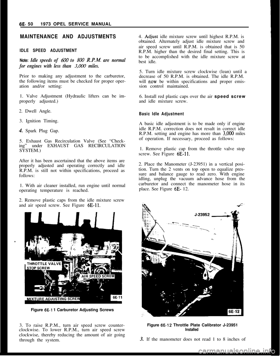
and air speed screw. See Figure
6E-11.Figure
6E-1 1 Carburetor Adjusting Screws
3. To raise R.P.M., turn air speed screw counter-
clockwise. To lower R.P.M., turn air speed screw
clockwise, thereby reducing the amount of air going
through the system.4.
Ad,just idle mixture screw until highest R.P.M. is
obtained. Alternately adjust idle mixture screw and
air speed screw until R.P.M. is obtained that is 50
R.P.M. higher than the desired final setting. This is
to be accomplished with the idle mixture screw at
best idle.
5. Turn idle mixture screw clockwise (lean) until a
decrease of 50 R.P.M. is obtained. The idle R.P.M.
will
n.ow be within specifications and proper emis-
sion control maintained.
6. Install red plastic caps over the air speed screw
and idle mixture screw.
Basic Idle AdjustmentA basic idle adjustment is to be made only if engine
idle R.P.M. correction does not result in correct idle
R.P.M. setting and engine has more than
3,OOO miles
of operation. If necessary, proceed as follows:
1. Remove plastic cap from the throttle valve stop
screw. See Figure
6E-11.2. Place the Manometer (J-23951) in a vertical posi-
tion. Turn the 2 vents on top open to equalize pres-
sure and balance gauge to read zero. With engine
idling, unplug the vacuum advance hose from the
carburetor and connect the manometer hose in its
place. See Figure 6E- 12.
Figure 6E-12 Throttle Plate Calibrator J-23951
Installed3. If the manometer does not read 1 to 8 inches of
Page 359 of 625
6G- 68 1973 OPEL SERVICE MANUAL
SPECIFICATIONS
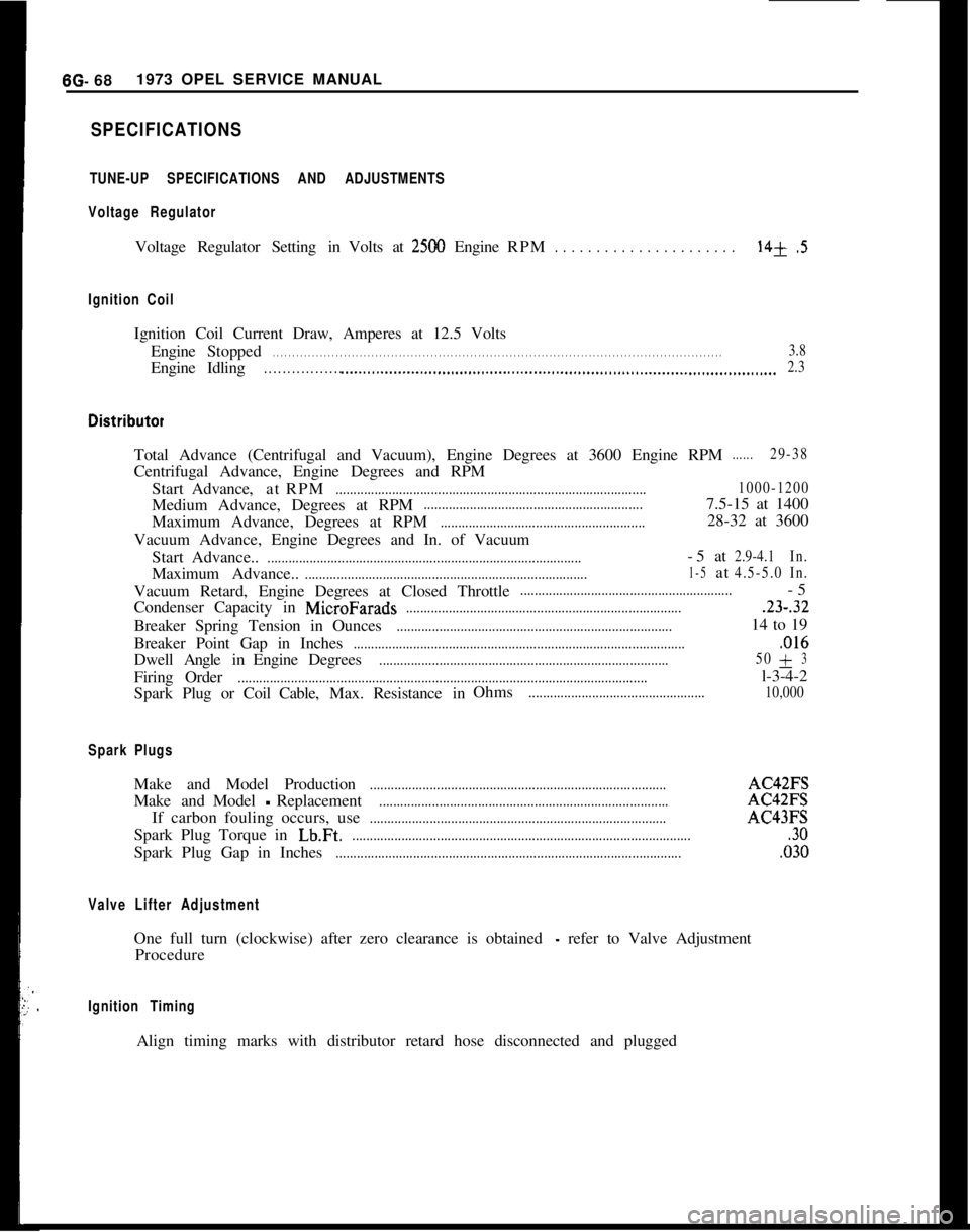
TUNE-UP SPECIFICATIONS AND ADJUSTMENTS
Voltage Regulator
Voltage Regulator Setting in Volts at2500 Engine RPM. . . . . . . . . . . . . . . . . . . . . .14+.5
Ignition Coil
Ignition Coil Current Draw, Amperes at 12.5 Volts
Engine Stopped
. . . . . . . . . . . . . . . . . . . . . . . . . . . . . . . . . . . . \
. . . . . . . . . . . . . . . . . . . . . . . . . . . . . . . . . . . . \
. . . . . . . . . . . . . . . . . . . . . . . . . . . . . . . . . . . . \
. . . . . .3.8
EngineIdling. . . . . . . . . . . . . . . . . .._.....................................................................\
........................... 2.3
Total Advance (Centrifugal and Vacuum), Engine Degrees at 3600 Engine \
RPM......29-38
Centrifugal Advance, Engine Degrees and RPM
Start Advance, atRPM
........................................................................\
................ 1000-1200
Medium Advance, Degrees at RPM..............................................................7.5-15 at 1400
Maximum Advance, Degrees at RPM
..........................................................28-32 at 3600
Vacuum Advance, Engine Degrees and In. of Vacuum Start Advance..
........................................................................\
.................-5at2.9-4.1 In.
Maximum Advance..........................................................................\
........1-5at4.5-5.0In.
Vacuum Retard, Engine Degrees at Closed Throttle............................................................-5
Condenser Capacity in
MicroFarads........................................................................\
.......23-.32
Breaker Spring Tension in Ounces........................................................................\
......14 to 19
Breaker Point Gap in Inches
........................................................................\
......................,016
Dwell AngleinEngine Degrees........................................................................\
.......... 50+3
Firing
Order........................................................................\
............................................l-3-4-2
Spark Plug or Coil Cable,Max.Resistance in Ohms
..................................................
10,000
Spark Plugs
Make and Model Production........................................................................\
............AC42FS
Make andModel
-Replacement........................................................................\
..........AC42FS
If carbon fouling occurs, use
........................................................................\
............AC43FS
Spark Plug Torque in
Lb.Ft.........................................................................\
.........................30
Spark Plug Gap in Inches........................................................................\
..........................,030
Valve Lifter Adjustment
One full turn (clockwise) after zero clearance is obtained - refer to Valve Adjustment
Procedure
Ignition Timing
Align timing marks with distributor retard hose disconnected and plugged\
Page 392 of 625

MANUAL TRANSMISSION70.31COUNTER SHAFT GEAR
THRUST WASHER\Figure 76.48 Installing Spacer Ring and Needle
Bearing Onto Mainshaft
fourth speed yoke should be positioned with rounded
notch at shaft hole portion of yoke toward rear. See
Figure 78. 47.
3. Install spiral pin, allowing
i/16” to 5/64” of pin
to protrude.
Installing First and Second Gear Shifter Shaft
1. Inspect shifter shaft carefully for burrs, and
remove with emery cloth. Burrs on shifter shaft will
prevent easy installation of shifter yoke and cam.
Lightly oil with transmission oil prior to installation.
Insert first and second gear shifter shaft through hole
in rear of case with three notches down and toward
rear of transmission, pushing shaft tirst through
firstand second gear shifter yoke, which should be posi-
tioned on first and second gear sliding gear with
shoulder toward front of case. To position first and
second gear shifter yoke on first and second gear
sliding gear, push reverse idler gear forward, engag-
ing the idler gear with the first and second gear
sliding gear. This will make room for positioningfirst and second gear shifter yoke. See Figure
7B-49.2. Continue to drive first and second gear shifter
shaft through shifter shaft cam, which should be
positioned as shown in Figure
7B-50.3. Install spiral pins to secure shifter yoke and shifter
shaft cam to first and second gear shifter shaft.
Installing Selector Shaft
1. Inspect selector shaft carefully for burrs, andFigure
78.49 Countergear Thrust Washers Installed
Figure
78-50 Position of “L” Shaped Selector Dog
remove with emery cloth. Burrs on shaft will prevent
easy installation of intermediate levers. Lightly oil
with transmission oil prior to installation. Insert new
selector shaft oil seals in holes on both sides of trans-
mission case and insert selector shaft into case and
through third, fourth, and reverse intermediate lever.
Third, fourth, and reverse intermediate lever should
be positioned on selector shaft, as shown in Figure
7B-51.2. Continue to push selector shaft through first and
second intermediate lever and through other side of
case. First and second intermediate lever should be
positioned on selector shaft, as shown in Figure 7B-
52. Selector shaft is rotated counterclockwise (when
looking from lever end of selector shaft) from work-
ing position to have spiral pin holes in shaft vertical
and in line with pin holes in intermediate levers. To
rotate selector shaft in this manner, the reverse gear
shifter shaft and its reverse speed shifter yoke must
be pushed rearward so that the reverse idler gear is
against rear of case.
Page 399 of 625
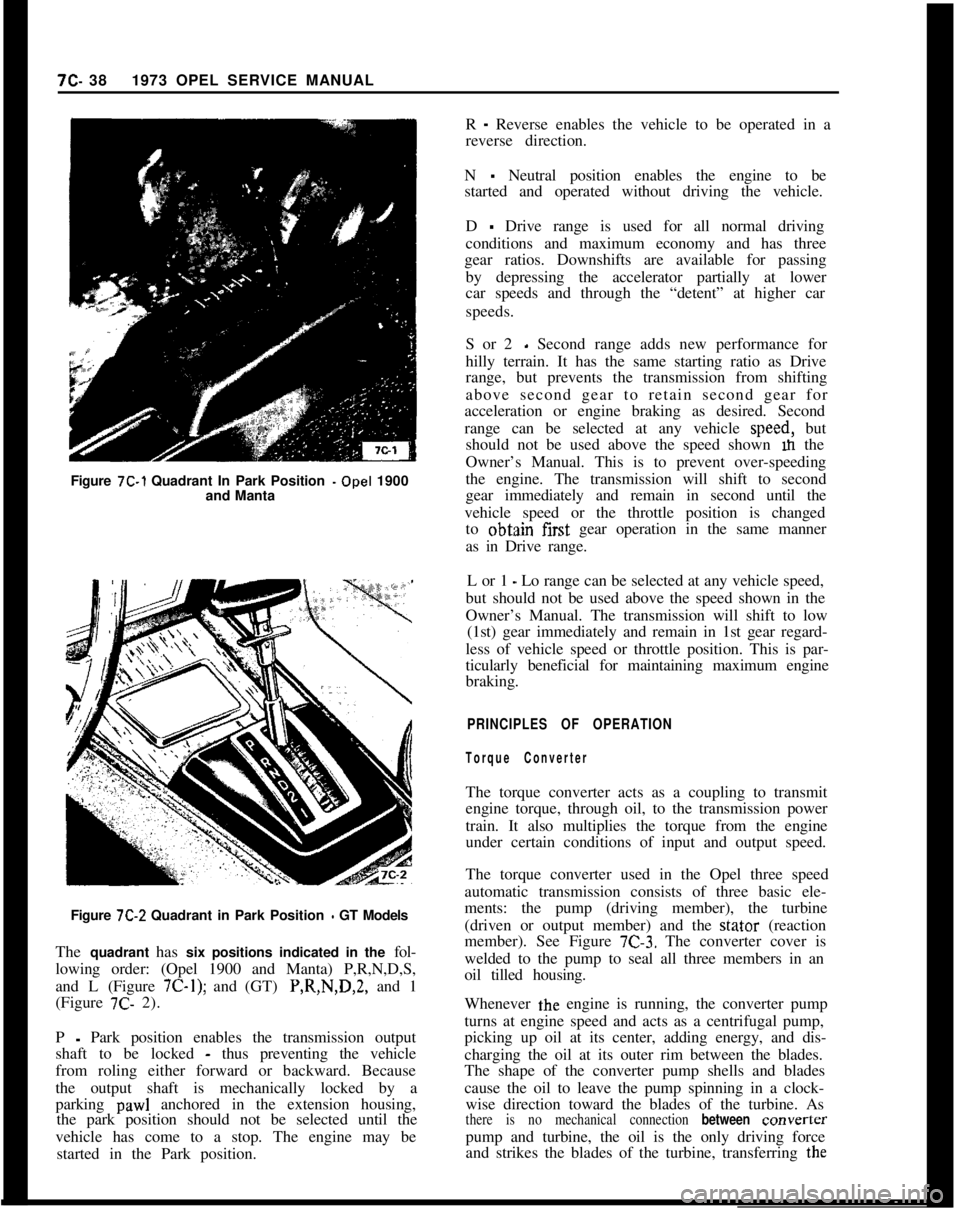
Figure 7C-1 Quadrant In Park Position -Opel 1900
and Manta7C- 381973 OPEL SERVICE MANUAL
R
- Reverse enables the vehicle to be operated in a
reverse direction.
N
- Neutral position enables the engine to be
started and operated without driving the vehicle.
D
- Drive range is used for all normal driving
conditions and maximum economy and has three
gear ratios. Downshifts are available for passing
by depressing the accelerator partially at lower
car speeds and through the “detent” at higher car
speeds.
S or 2
- Second range adds new performance for
hilly terrain. It has the same starting ratio as Drive
range, but prevents the transmission from shifting
above second gear to retain second gear for
acceleration or engine braking as desired. Second
range can be selected at any vehicle speed, but
should not be used above the speed shown m the
Owner’s Manual. This is to prevent over-speeding
the engine. The transmission will shift to second
gear immediately and remain in second until the
vehicle speed or the throttle position is changed
to obtajn first gear operation in the same manner
as in Drive range.
L or 1
- Lo range can be selected at any vehicle speed,
but should not be used above the speed shown in the
Owner’s Manual. The transmission will shift to low
(1st) gear immediately and remain in 1st gear regard-
less of vehicle speed or throttle position. This is par-
ticularly beneficial for maintaining maximum engine
braking.
PRINCIPLES OF OPERATION
Torque ConverterThe torque converter acts as a coupling to transmit
engine torque, through oil, to the transmission power
train. It also multiplies the torque from the engine
under certain conditions of input and output speed.
Figure
7C-2 Quadrant in Park Position - GT Models
The quadrant has six positions indicated in the fol-
lowing order: (Opel 1900 and Manta) P,R,N,D,S,
and L (Figure
7C-1); and (GT) P,R,N,D,2, and 1
(Figure 7C- 2).The torque converter used in the Opel three speed
automatic transmission consists of three basic ele-
ments: the pump (driving member), the turbine
(driven or output member) and the stator (reaction
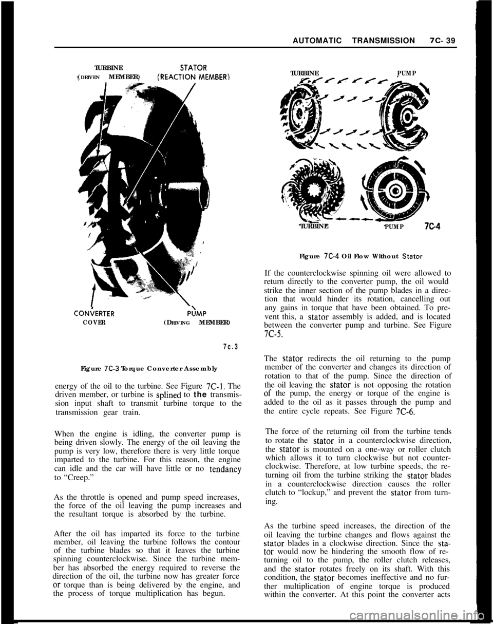
member). See Figure
7C-3. The converter cover is
welded to the pump to seal all three members in an
oil tilled housing.
P
- Park position enables the transmission output
shaft to be locked
- thus preventing the vehicle
from roling either forward or backward. Because
the output shaft is mechanically locked by a
parking
paw1 anchored in the extension housing,
the park position should not be selected until the
vehicle has come to a stop. The engine may be
started in the Park position.Whenever the engine is running, the converter pump
turns at engine speed and acts as a centrifugal pump,
picking up oil at its center, adding energy, and dis-
charging the oil at its outer rim between the blades.
The shape of the converter pump shells and blades
cause the oil to leave the pump spinning in a clock-
wise direction toward the blades of the turbine. Asthere is no mechanical connection between converterpump and turbine, the oil is the only driving force
and strikes the blades of the turbine, transferring the
Page 400 of 625
AUTOMATIC TRANSMISSION7c- 39
TURBINESTATOR
(DRIVEN MEMBER)fREACTION
MEMBER)CON;ERTER
COVERP;MP
(DRIVING MEMBER)
7c.3Figure
7C-3 Torque Converter Assembly
energy of the oil to the turbine. See Figure
7C-1. The
driven member, or turbine is splined to the transmis-
sion input shaft to transmit turbine torque to the
transmission gear train.
When the engine is idling, the converter pump is
being driven slowly. The energy of the oil leaving the
pump is very low, therefore there is very little torque
imparted to the turbine. For this reason, the engine
can idle and the car will have little or no tendancy
to “Creep.”
As the throttle is opened and pump speed increases,
the force of the oil leaving the pump increases and
the resultant torque is absorbed by the turbine.
After the oil has imparted its force to the turbine
member, oil leaving the turbine follows the contour
of the turbine blades so that it leaves the turbine
spinning counterclockwise. Since the turbine mem-
ber has absorbed the energy required to reverse the
direction of the oil, the turbine now has greater forceor torque than is being delivered by the engine, and
the process of torque multiplication has begun.TURBINE
PUMPTURBINE
PUMP7c4Figure
7C-4 Oil Flow Without Stator
If the counterclockwise spinning oil were allowed to
return directly to the converter pump, the oil would
strike the inner section of the pump blades in a direc-
tion that would hinder its rotation, cancelling out
any gains in torque that have been obtained. To pre-
vent this, a stator assembly is added, and is located
between the converter pump and turbine. See Figure7c-5.
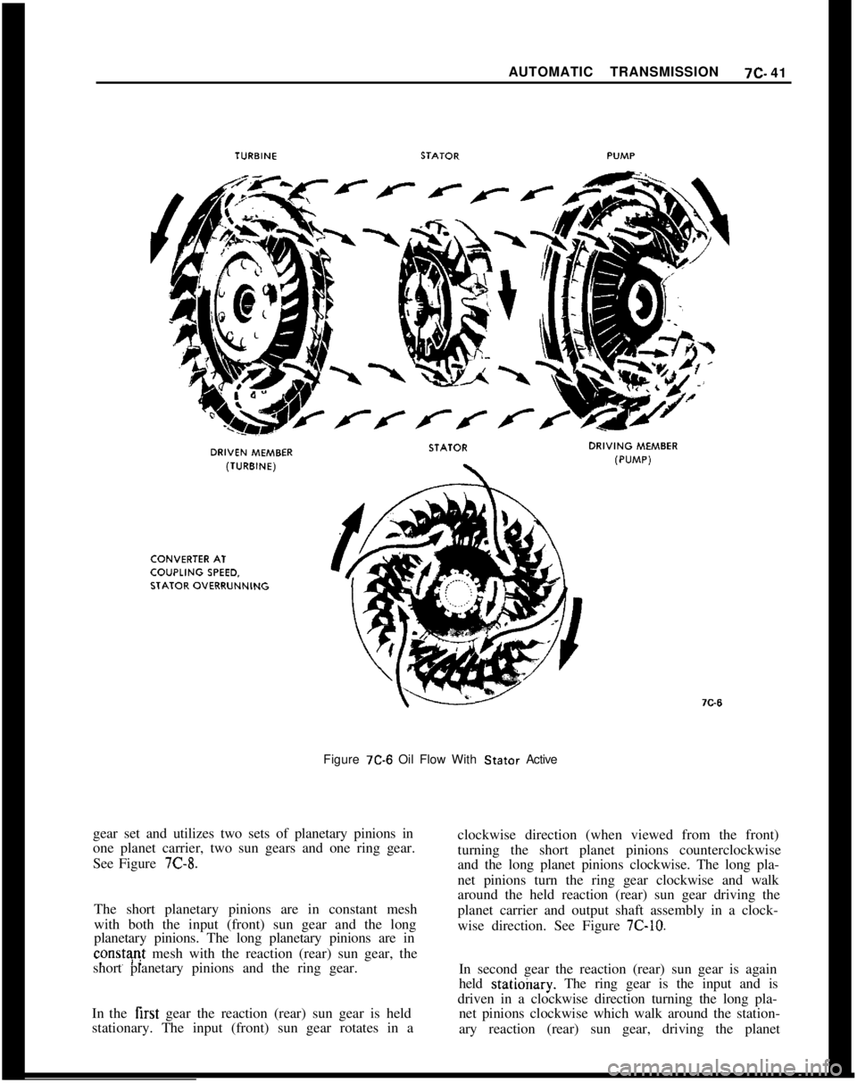
The stator redirects the oil returning to the pump
member of the converter and changes its direction of
rotation to that of the pump. Since the direction of
the oil leaving the stator is not opposing the rotationof the pump, the energy or torque of the engine is
added to the oil as it passes through the
the entire cycle repeats. See Figure
7C-6.pump and
The force of the returning oil from the turbine tends
to rotate the stator in a counterclockwise direction,
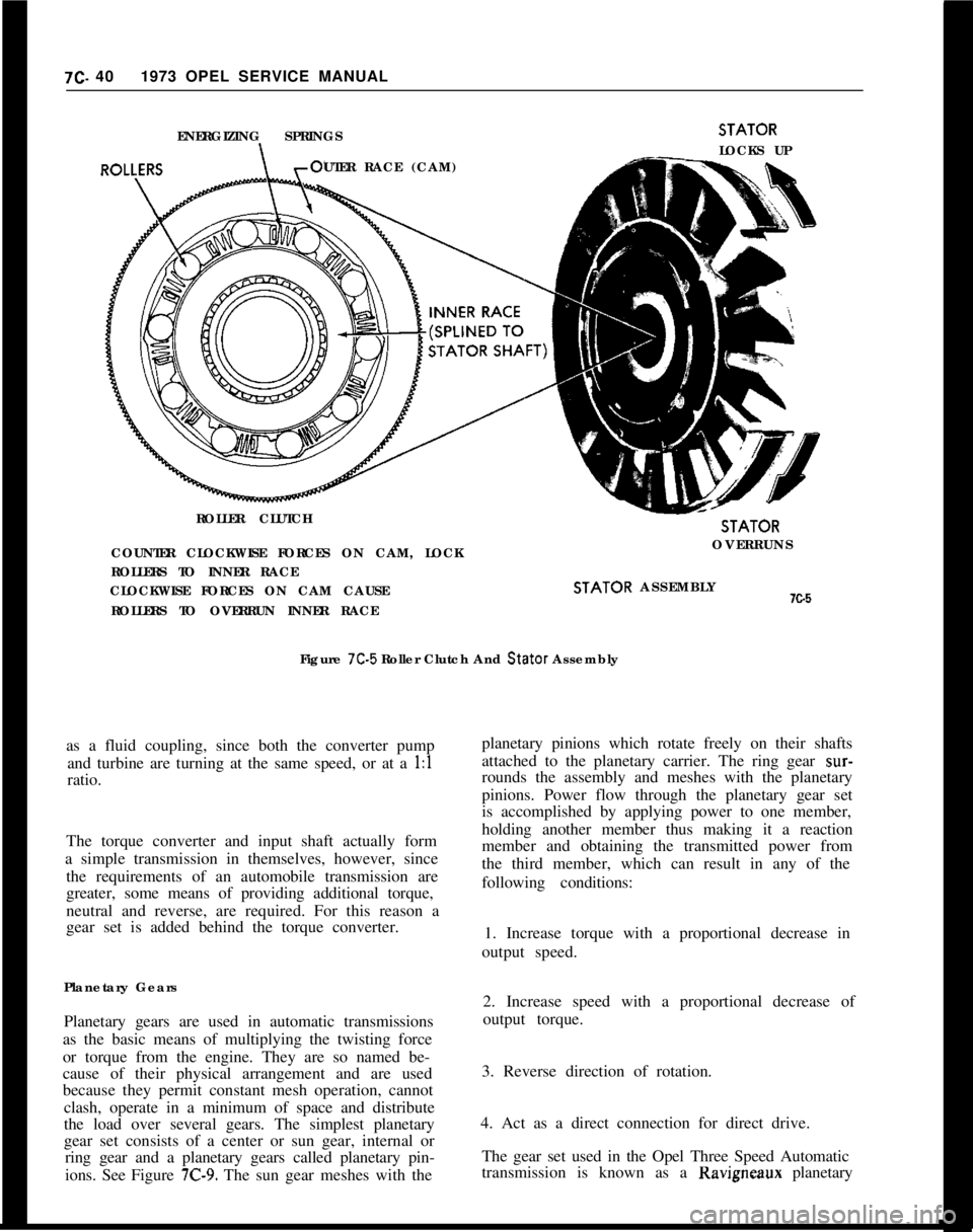
the stator is mounted on a one-way or roller clutch
which allows it to turn clockwise but not counter-
clockwise. Therefore, at low turbine speeds, the re-
turning oil from the turbine striking the stator blades
in a counterclockwise direction causes the roller
clutch to “lockup,” and prevent the stator from turn-
ing.
As the turbine speed increases, the direction of the
oil leaving the turbine changes and flows against thestator blades in a clockwise direction. Since the sta-tar would now be hindering the smooth flow of re-
turning oil to the pump, the roller clutch releases,
and the stator rotates freely on its shaft. With this
condition, the stator becomes ineffective and no fur-
ther multiplication of engine torque is produced
within the converter. At this point the converter acts
Page 401 of 625
7C- 401973 OPEL SERVICE MANUAL
ENERGIZING SPRINGS
UTER RACE (CAM)
ROLLER CLUTCHSTATOR
LOCKS UPSTATOR
COUNTER CLOCKWISE FORCES ON CAM, LOCKOVERRUNS
ROLLERS TO INNER RACE
CLOCKWISE FORCES ON CAM CAUSESTATOR ASSEMBLYx.5
ROLLERS TO OVERRUN INNER RACE
Figure 7C-5 Roller Clutch And Stator Assembly
as a fluid coupling, since both the converter pump
and turbine are turning at the same speed, or at a 1:l
ratio.
The torque converter and input shaft actually form
a simple transmission in themselves, however, since
the requirements of an automobile transmission are
greater, some means of providing additional torque,
neutral and reverse, are required. For this reason a
gear set is added behind the torque converter.
Planetary Gears
Planetary gears are used in automatic transmissions
as the basic means of multiplying the twisting force
or torque from the engine. They are so named be-
cause of their physical arrangement and are used
because they permit constant mesh operation, cannot
clash, operate in a minimum of space and distribute
the load over several gears. The simplest planetary
gear set consists of a center or sun gear, internal or
ring gear and a planetary gears called planetary pin-
ions. See Figure
7C-9. The sun gear meshes with theplanetary pinions which rotate freely on their shafts
attached to the planetary carrier. The ring gear
sur-rounds the assembly and meshes with the planetary
pinions. Power flow through the planetary gear set
is accomplished by applying power to one member,
holding another member thus making it a reaction
member and obtaining the transmitted power from
the third member, which can result in any of the
following conditions:
1. Increase torque with a proportional decrease in
output speed.
2. Increase speed with a proportional decrease of
output torque.
3. Reverse direction of rotation.
4. Act as a direct connection for direct drive.
The gear set used in the Opel Three Speed Automatic
transmission is known as a Ravigneaux planetary
Page 402 of 625
AUTOMATIC TRANSMISSION7c- 41
Figure
7C-6 Oil Flow With Stator Active
gear set and utilizes two sets of planetary pinions in
one planet carrier, two sun gears and one ring gear.
See Figure
7C-8.The short planetary pinions are in constant mesh
with both the input (front) sun gear and the long
planetary pinions. The long planetary pinions are inconstr$ mesh with the reaction (rear) sun gear, the
short planetary pinions and the ring gear.
In the first gear the reaction (rear) sun gear is held
stationary. The input (front) sun gear rotates in aclockwise direction (when viewed from the front)
turning the short planet pinions counterclockwise
and the long planet pinions clockwise. The long pla-
net pinions turn the ring gear clockwise and walk
around the held reaction (rear) sun gear driving the
planet carrier and output shaft assembly in a clock-
wise direction. See Figure
7C-10.In second gear the reaction (rear) sun gear is again
held statioinry. The ring gear is the input and is
driven in a clockwise direction turning the long pla-
net pinions clockwise which walk around the station-
ary reaction (rear) sun gear, driving the planet
Page 403 of 625
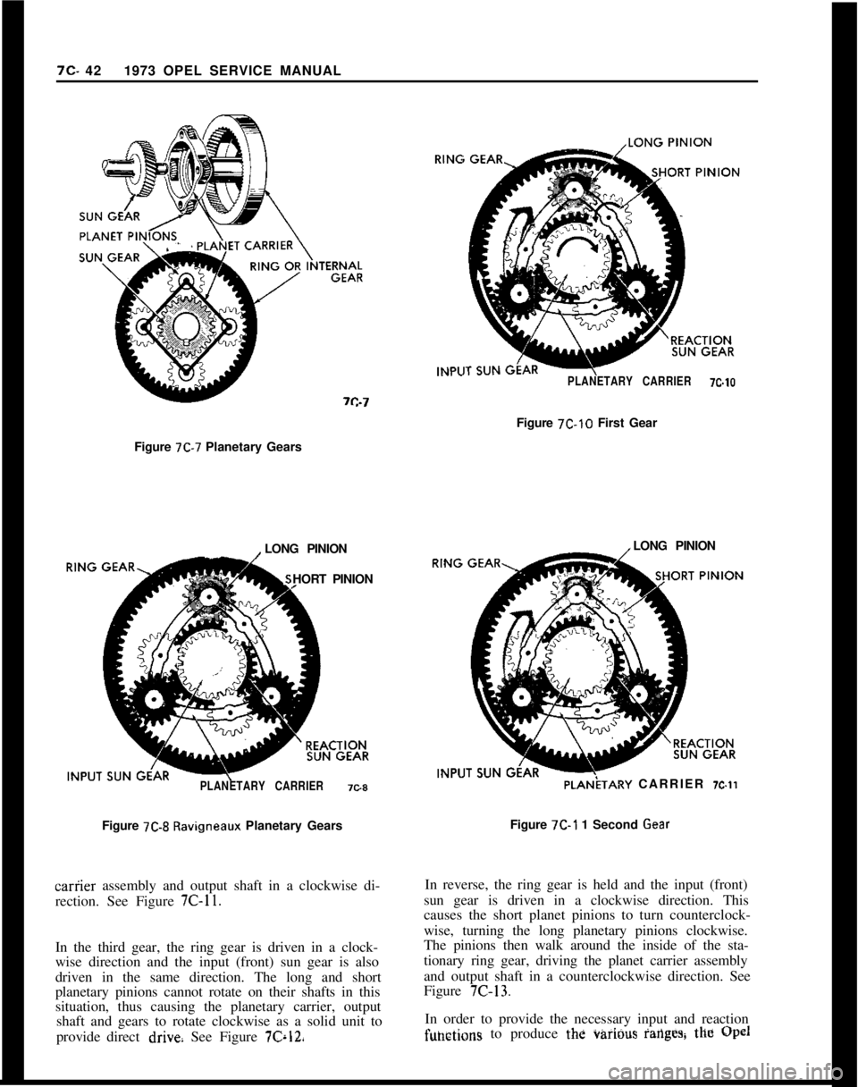
7C. 421973 OPEL SERVICE MANUALPLANETARY CARRIER7c.toFigure
712-10 First Gear
Figure
7C-7 Planetary Gears
LONG PINION
HORT PINION
PLANETARY CARRIER7C8Figure
7C-8 Ravigneaux Planetary Gearscariier assembly and output shaft in a clockwise di-
rection. See Figure
7C-11.In the third gear, the ring gear is driven in a clock-
wise direction and the input (front) sun gear is also
driven in the same direction. The long and short
planetary pinions cannot rotate on their shafts in this
situation, thus causing the planetary carrier, output
shaft and gears to rotate clockwise as a solid unit to
provide direct
drive See Figure 76x12,LONG PINIONPLANiTARY CARRIER
X.11Figure
7C-1 1 Second GearIn reverse, the ring gear is held and the input (front)
sun gear is driven in a clockwise direction. This
causes the short planet pinions to turn counterclock-
wise, turning the long planetary pinions clockwise.
The pinions then walk around the inside of the sta-
tionary ring gear, driving the planet carrier assembly
and output shaft in a counterclockwise direction. See
Figure
7C-13.In order to provide the necessary input and reaction
fuhftions to produce the i&iiOus iarlgesg the @al