air filter OPEL GT-R 1973 Service Manual
[x] Cancel search | Manufacturer: OPEL, Model Year: 1973, Model line: GT-R, Model: OPEL GT-R 1973Pages: 625, PDF Size: 17.22 MB
Page 20 of 625
LUBRICATION AND MAINTENANCE OC-11
Throttle Linkage
Check for damaged or missing parts, interference or
binding. Any deficiencies should be corrected with-
out delay.
Headlights
Check for proper aim. Correct as necessary. More
frequent checks should be made if oncoming motor-
ists signal when you are already using your low
beams, or if illumination of the area ‘ahead seems
inadequate.
Underbody
In geographic areas using a heavy concentration of
road salt or other corrosive materials for snow re-
moval or road dust control, flush and inspect the
complete under side of the car at least once each
year, preferably after a winter’s exposure. Particular
attention should be given to cleaning out underbody
members where dirt and other foreign materials may
have collected.
EMISSION CONTROL MAINTENANCE
Thermostatically Controlled Air Cleaner
Inspect installation to make certain that all hoses and
ducts are connected and correctly installed. Also,
check valve for proper operation.
Carburetor Choke
Check choke mechanism for free operation. A bind-
ing condition may have developed from petroleum
gum formation on the choke shaft or from overtight-
ening of air cleaner clamp. Also check electric choke
terminal connections and fuse.
Timing, Dwell and Distributor
Adjust timing and dwell accurately as outlined under
Tune-Up in Group 6 at the first 4 months or 6,ooOmiles of operation, then at 12 month or
12,OQO mile
intervals. Adjustments must be made with test equip-
ment known to be accurate.
Replace distributor points every 12 months or 12,000
miles and carefully clean and inspect the complete
distributor cap to prevent misfiring and deteriora-
tion.
Carburetor and Idle
SpeedTorque carburetor attaching bolts and/or nuts to 12
ft.lbs. to compensate for compression of gasket atiirst 4 months or 6,000 miles of vehicle operation.Adjust idle speed to specifications with known accu-
rate equipment.
Proper functioning of the carburetor is particularly
essential to control of emissions. Correct mixtures
for emission compliance and idle quality have been
preset by Opel. Plastic idle mixture limiters have
been installed on the idle mixture screw, idle air
screw, and throttle stop screw to preclude unauthor-
ized adjustment. The plastic caps on the idle mixture
screw and the idle adjustment screw must be
removed to perform an idle speed adjustment. The
plastic cap on the throttle stop screw is not to be
removed unless some major carburetor repair or re-
placement which affects the throttle stop screw ad-
justment has been necessary.
Carburetor Fuel Inlet Filter
Replace filter at 12 month or
12,OCO mile intervals
or more often if clogged.
Spark Plugs
Replace at
6,ooO mile intervals when operating with
leaded fuels or at 12,000 mile intervals when using
unleaded fuels. Use of leaded fuels results in lead
deposits on spark plugs and can cause misfiring at
mileages less than
12,OilO miles. Where misfiring oc-
curs prior to
6,ooO miles, spark plugs in good condi-
tion can often be cleaned, tested and reinstalled in an
engine with acceptable results.
Spark Plug Wires
Inspect spark plug wires for evidence of checking or
cracking of exterior insulation and tight fit in the
distributor cap and at the spark plugs. Exterior of
wires should be cleaned, any evidence of corrosion
on ends removed and wire replace if deteriorated.
Positive Crankcase Ventilation System
The PCV metered orifice should be cleaned at 12,000
mile intervals under normal use, and at 6,000 mile
intervals when the vehicle is used under the follow-
ing conditions: driving in dusty conditions, extensive
idling, trailer pulling and short trip operation at
freezing temperatures (engine not thoroughly
warmed-up).
Evaporation Control System
Check all fuel and vapor lines and hoses for proper
connections and correct routing as well as condition.
Remove canister and check for cracks or damage.
Replace damaged or deteriorated parts as necessary.
Replace filter in open end of canister at 24month/24,000 mile intervals.
Page 261 of 625
CONTENTS
SubjectPage No.
DESCRIPTION AND OPERATION:
Power
BrakeBooster. . . . . . . . . . . . . . . . . . . . . . . . . . . . . . . . . . . . . . . . . . . . . . . . . . . . . . . .Master
Cylinder
. . . . . . . . . . . . . . . . . . . . . . . . . . . . . . . . . . . . . . . . . . . . . . . . . . . . . . . . . . . . . . . . . .DIAGNOSIS:
Power
Brake
,UnitTroubleDiagnosis. . . . . . . . . . . . . . . . . . . . . . . . . .MAINTENANCE AND ADJUSTMENTS:
Checking Brake Booster Operation
. . . . . . . . . . . . . . . . . . . . . . . . . . . .Brake Booster Filter Service
. . . . . . . . . . . . . . . . . . . . . . . . . . . . . . . . . . . . . . . . . ..Vacuum Control Valve Service
. . . . . . . . . . . . . . . . . . . . . . . . . . . . . . . . . . . . . .MAJOR REPAIR:
5A-2
5A-2SA-4SA-5
5A-65A-6
Brake Booster Removal and Installation
. . . . . . . . . . . . . . . . . .Master Cylinder Overhaul
. . . . . . . . . . . . . . . . . . . . . . . . . . . . . . . . . . * . . . . . . . . . . .SPECIFICATIONS:
General
Specifications
. . . . . . . . . . . . . . . . . . . . . . . . . . . . . . . . . . . . . . . . . . . . . . . . . . . . . .SA-6
5A-7
5A-95A. 21973 OPEL SERVICE MANUAL
POWER BRAKE BOOSTER AND MASTER CYLINDER
DESCRIPTION AND OPERATION
POWER BRAKE BOOSTERThe vacuum power cylinder contains the power pis-
ton assembly which houses the control valve and
reaction mechanism and the power piston return
spring. The control valve is composed of the air valveand the floating control valve assembly. The reaction
mechanism consists of a hydraulic piston, reaction
plate, and a series of springs. An air filter element is
assembled around the push rod and fills the cavity
inside the hub of the power piston. This keeps dirt
and dust from entering the vacuum booster. The
push rod, which operates the air valve, projects out
of the end of the power cylinder ‘housing through a
boot.MASTER CYLINDER
The master cylinder is composed pf a primary pistonand secondary piston; it is supplied with fluid from
two separate reservoirs. A check valve is mounted onthe primary circuit which supplies fluid to the rear
brakes. This keeps a slight static pressure in the rear
brake system. When the pedal is depressed, the pushrod moves the two pistons forward simultaneously
until the seals of the two pistons cover the compen-
sating ports in the cylinder. The pressure is increasedin the two chambers simultaneously, thus supplying
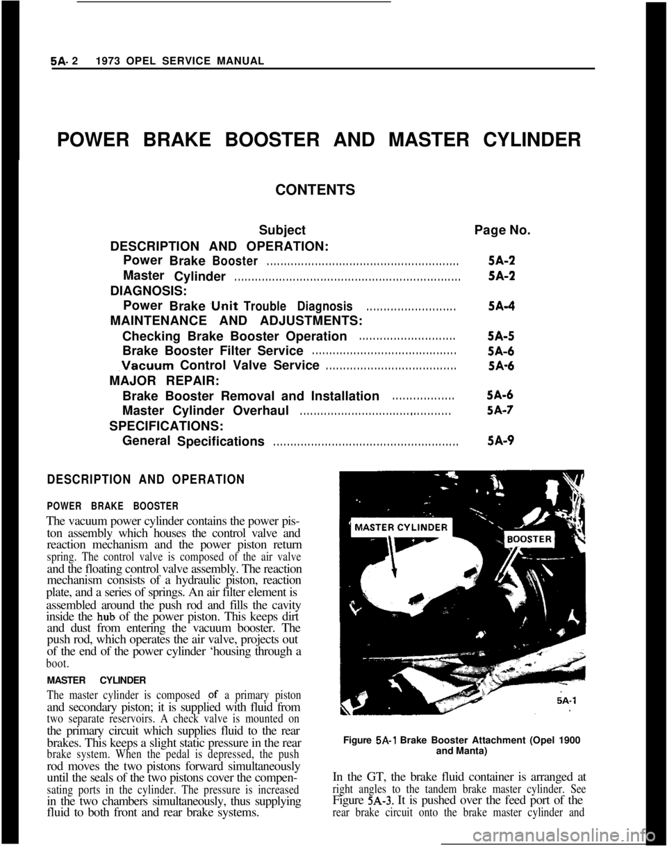
fluid to both front and rear brake systems.Figure
5A-1 Brake Booster Attachment (Opel 1900
and Manta)
In the GT, the brake fluid container is arranged at
right angles to the tandem brake master cylinder. SeeFigure
5A-3. It is pushed over the feed port of the
rear brake circuit onto the brake master cylinder and
Page 263 of 625

5A- 41973 OPEL SERVICE MANUAL
Figure
5A-4 Brake Pedal and Master Cylinder
Attachment
(GT)
v1I cy
1 THRUST SPRING
2 VALVE SEAT
3 HOUSING
Figure
5A-5 Vacuum Control Valve
DIAGNOSIS
POWER BRAKE UNIT TROUBLE DIAGNOSIS
ConditionPossible Cause
CorrectionHard Pedal
1. Broken or damagedhydraulic
brake lines.
1, Inspect and replace as necessary.
2. Vacuum failure.
2. Check for:a) Faulty vacuum check valve or
grommet
- replace.
b) Collapsed or damaged vacuum
hose
- replace.
c) Plugged or loose vacuum
fitting
- repair.
d) Faulty air valve seal
drsupport plate seal
- replace.
e) Damaged floating control valve.
3. Defective diaphragm.
4. Restricted air filter
element.3. Replace
4. Replace5. Defective apply piston5. Repair and replace master
seals.cylinder.
6. Cracked or broken powerpistons or retainer.6. Replace power unit.
Page 264 of 625

POWER BRAKE BOOSTER AND MASTER CYLINDER5A- 5ConditionGrabby Brakes (Apparent
Off-and On Condition)
Possible Cause1. Broken or damaged
hydraulic brake lines.Correction1. Inspect and replace, as
“CXXSSary.2. Insufficient fluid in
master cylinder.
3. Defective master cylinder
seals.4. Cracked master cylinder
casting.2. Fill reservoirs with approved
brake fluid check for leaks.
3. Repair or replace, asnecessary.4. Replace
5. Leaks at front disc brake
calipers or rear wheel
cylinders
in pipes or connections.5. Inspect and repair, as
necessary.Brakes Fail to Release6. Air in hydraulic system.
1. Blocked passage in power
piston.
2. Air valve sticking shut.6. Bleed system.
1. Inspect and repair or replace,
as necessary.
2. Check for proper lubrication of
air valve “0” ring.
3. Broken piston return spring
3. Replace
master cylinder.
4. Tight pedal linkage.5. Repair or replace, as
necessary.
MAINTENANCE AND ADJUSTMENTS
CHECKING BRAKE BOOSTER OPERATIONThe operation of the brake booster can be checked by
simple means and without any special devices.
1. With engine off, first clear the booster of any
vacuum by depressing brake pedal several times.
2. Then depress brake pedal and start engine. If the
vacuum system is working correctly, the brake pedal,
kept under even foot pressure, moves farther down-
wards due to the additional pressure developed by
the booster. Should the brake pedal not move farther
downwards, the vacuum system is deficient. In this
case check the vacuum hose to booster, to vacuum
control valve and to engine intake manifold connec-
tions.3. If the vacuum system operates properly, the defect
is in the brake booster itself. A dirty filter impairs oreven prevents air from entering into the booster and
thereby the formation of a difference in pressure in
the vacuum cylinder.
Repairs cannot be carried out on the brake booster.
If no deficiency can be found in the vacuum system
or filter, the brake booster has to be replaced.
Under normal operating conditions the brake
booster requires no service. However, under adverse
conditions such as frequent driving on sandy or
dusty roads, the filter and sound deadener should be
replaced occasionally. To do so, the brake booster
must be removed but it isn’t necessary to detach the
master cylinder.
BRAKE BOOSTER FILTER SERVICEUnder normal operating conditions the filter need
not be exchanged for a new one.
Under adverse operating conditions
- frequent driv-
Page 265 of 625
5A- 61973 OPEL SERVICE MANUAL
ing on dusty and sandy roads - the filter and sound
deadener should occasionally be replaced. To do so,
brake booster has to be removed without detaching
brake master cylinder.
Proceed as follows:
1. Remove protective cap (boot).
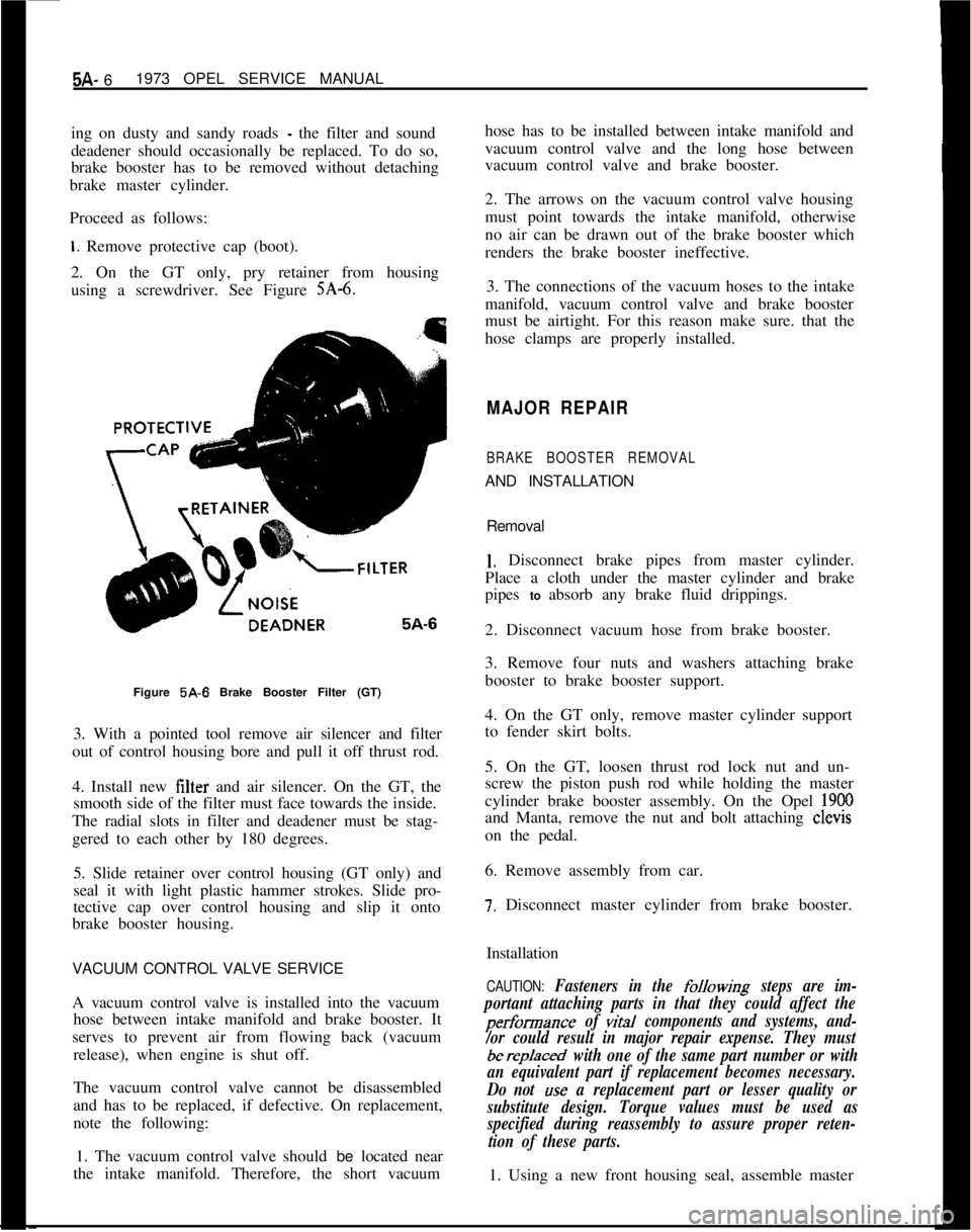
2. On the GT only, pry retainer from housing
using a screwdriver. See Figure
SA-6.Figure 5A-6 Brake Booster Filter (GT)
3. With a pointed tool remove air silencer and filter
out of control housing bore and pull it off thrust rod.
4. Install new filter and air silencer. On the GT, the
smooth side of the filter must face towards the inside.
The radial slots in filter and deadener must be stag-
gered to each other by 180 degrees.
5. Slide retainer over control housing (GT only) and
seal it with light plastic hammer strokes. Slide pro-
tective cap over control housing and slip it onto
brake booster housing.
VACUUM CONTROL VALVE SERVICE
A vacuum control valve is installed into the vacuum
hose between intake manifold and brake booster. It
serves to prevent air from flowing back (vacuum
release), when engine is shut off.
The vacuum control valve cannot be disassembled
and has to be replaced, if defective. On replacement,
note the following:
1. The vacuum control valve should be located near
the intake manifold. Therefore, the short vacuumhose has to be installed between intake manifold and
vacuum control valve and the long hose between
vacuum control valve and brake booster.
2. The arrows on the vacuum control valve housing
must point towards the intake manifold, otherwise
no air can be drawn out of the brake booster which
renders the brake booster ineffective.
3. The connections of the vacuum hoses to the intake
manifold, vacuum control valve and brake booster
must be airtight. For this reason make sure. that the
hose clamps are properly installed.
MAJOR REPAIR
BRAKE BOOSTER REMOVALAND INSTALLATION
Removal
1. Disconnect brake pipes from master cylinder.
Place a cloth under the master cylinder and brake
pipes to absorb any brake fluid drippings.
2. Disconnect vacuum hose from brake booster.
3. Remove four nuts and washers attaching brake
booster to brake booster support.
4. On the GT only, remove master cylinder support
to fender skirt bolts.
5. On the GT, loosen thrust rod lock nut and un-
screw the piston push rod while holding the master
cylinder brake booster assembly. On the Opel
1900and Manta, remove the nut and bolt attaching clevis
on the pedal.
6. Remove assembly from car.
7. Disconnect master cylinder from brake booster.
Installation
CAUTION: Fasteners in the folkwing steps are im-
portant attaching parts in that they could affect the
performance of vital components and systems, and-
/or could result in major repair expense. They must
berep/aced, with one of the same part number or with
an equivalent part if replacement becomes necessary.
Do not
use a replacement part or lesser quality or
substitute design. Torque values must be used as
specified during reassembly to assure proper reten-
tion of these parts.1. Using a new front housing seal, assemble master
Page 328 of 625
FUEL SYSTEMSC- 37
must always be removed before the distributor can be
removed.
EVAPORATION CONTROL SYSTEM1. The function of the fuel evaporation control sys-
tem is to absorb the fuel vapors developing in the fuel
tank, especially when vehicle is parked, due to at-
mospheric pressure and temperature influences, and
to release these fuel vapors during vehicle operation.
2. This system utilizes the property of the activated
carbon to absorb and expel fuel vapors. The activated
carbon container is installed on the left front side of
the engine compartment. The fuel tank has a
non-vented tiller cap. Vent hoses are joined in the area of
the tank. A plastic evaporation line leads from there
along vehicle underbody to the activated carbon con-
tainer.
3. A small tube above the throttle valve body con-
nects the carburetor to the activated carbon con-
tainer. In this way, the fuel vapor collected in the
activated carbon container is fed through the carbu-
retor into the combustion chambers during engine
operation.
4. The carburetor is provided with an internal and
outside ventilation, the activated carbon container is
also connected to the outside ventilation (only effec-
tive when engine is idling). In this way, the fuel
vapors escaping to the outside during engine idle are
collected by the activated carbon container and fed
into the combustion chambers.
5. The vent lines are connected to the upper part of
the activated carbon container. Fresh air enters
through a foam rubber filter at the lower part andflows, together with the fuel vapor, to the carburetor.
Metered bores in the hose fittings of the fuel tank
control the air
- and fuel vapor flow through the
activated carbon container to the carburetor, and the
pressure release in the fuel tank and ensure complete
purging of the carbon container.
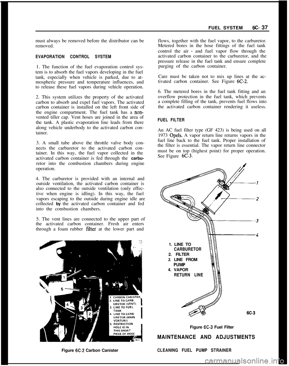
Care must be taken not to mix up lines at the ac-
tivated carbon container. See Figure
6C-2.6. The metered bores in the fuel tank fitting and an
overflow protection in the fuel tank, which prevents
a complete filling of the tank, prevents fuel flows into
the activated carbon container rendering it useless.
FUEL FILTERAn AC fuel filter type (GF 423) is being used on all
1973 Opels. A vapor return line returns vapors in the
fuel line back to the fuel tank. Proper installation of
the filter is essential. The vapor return line connector
must be on top (highest point) for proper operation.
See Figure
6C-3.1. LINE TO
CARBURETOR2. FILTER
3. LINE FROM
4. VAPOR
RETURN LINE
6C-3Figure
6C-3 Fuel Filter
MAINTENANCE AND ADJUSTMENTSFigure
6C-2 Carbon CanisterCLEANING FUEL PUMP STRAINER
Page 329 of 625
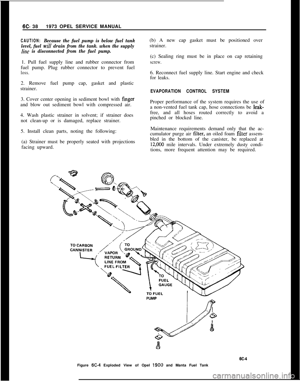
6C- 381973 OPEL SERVICE MANUALCAUTION:Because the fuel pump is below fuel tank
level, fuel
will drain from the tank. when the supply
hne is disconnected from the fuel pump.1. Pull fuel supply line and rubber connector from
fuel pump. Plug rubber connector to prevent fuel
loss.2. Remove fuel pump cap, gasket and plastic
strainer.
3. Cover center opening in sediment bowl with finger
and blow out sediment bowl with compressed air.
4. Wash plastic strainer in solvent; if strainer does
not clean-up or is damaged, replace strainer.
5. Install clean parts, noting the following:
(a) Strainer must be properly seated with projections
facing upward.(b) A new cap gasket must be positioned over
strainer.
(c) Sealing ring must be in place on cap retaining
screw.6. Reconnect fuel supply line. Start engine and check
for leaks.
EVAPORATION CONTROL SYSTEMProper performance of the system requires the use of
a non-vented fuel tank cap, hose connections be leak-
free, and all hoses routed correctly to avoid a
pinched or blocked line.
Maintenance requirements demand only that the ac-
cumulator purge air tilter, an oiled foam filter assem-
bled in the bottom of the canister, be replaced at
12,CKO mile intervals. Under extremely dusty condi-
tions, more frequent attention may be required.
Figure
W-4 Exploded View of Opel 1900 and Manta Fuel Tank
Page 349 of 625
6E- 581973 OPEL SERVICE MANUAL
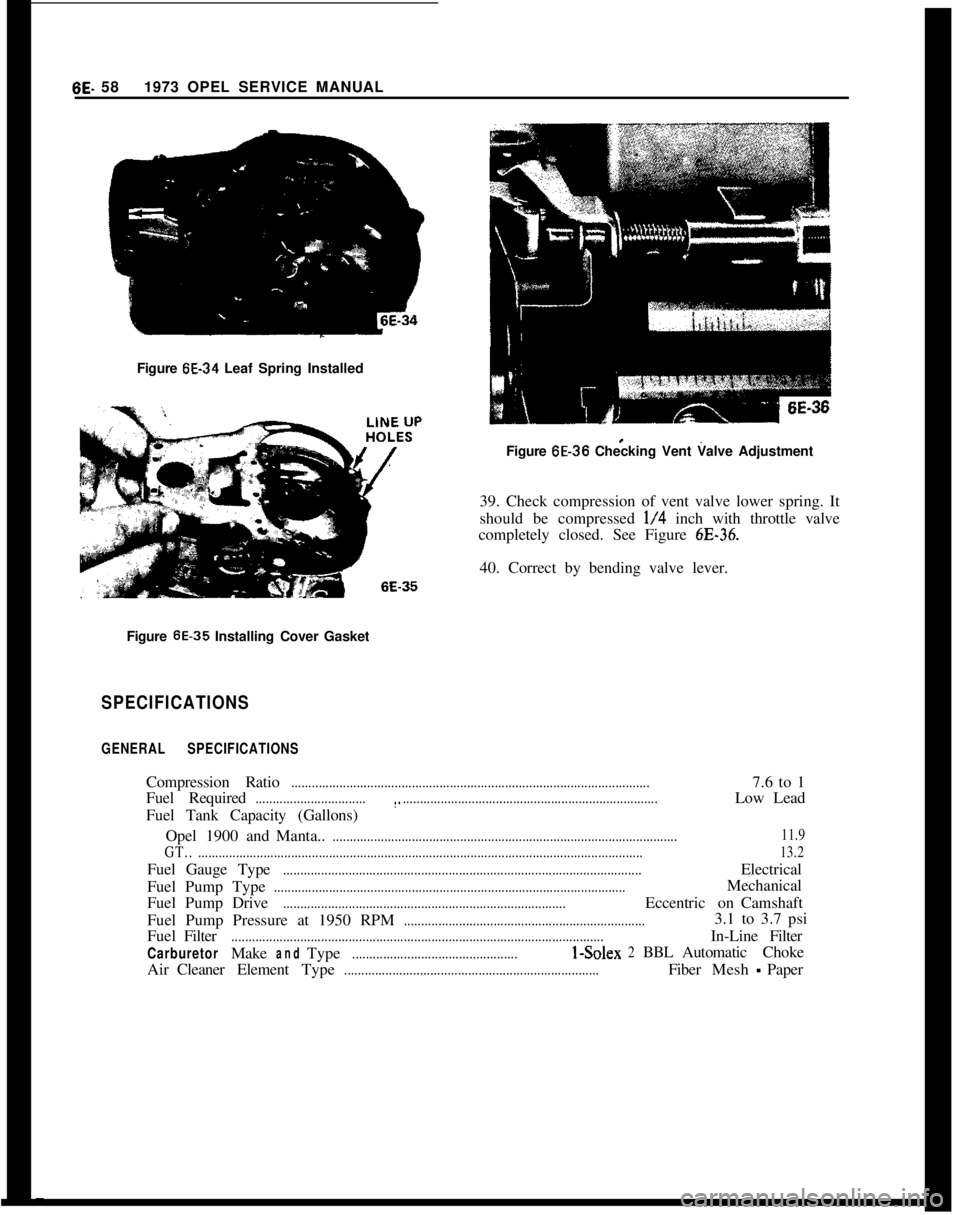
Figure 6E-34 Leaf Spring Installed
1 6E-36
Figure 6E-36 Checking Vent Valve Adjustment
39. Check compression of vent valve lower spring. It
should be compressed
l/4 inch with throttle valve
completely closed. See Figure
6E-36.40. Correct by bending valve lever.
Figure
6E-35 Installing Cover Gasket
SPECIFICATIONS
GENERAL SPECIFICATIONSCompression Ratio
........................................................................................................7.6 to 1
Fuel Required
................................(...........................................................................Low Lead
Fuel Tank Capacity (Gallons)
Opel1900andManta..
....................................................................................................11.9
GT...................................................................................................................................13.2Fuel Gauge Type
........................................................................................................Electrical
FuelPumpType
......................................................................................................Mechanical
FuelPumpDrive
..................................................................................EccentriconCamshaft
Fuel Pump Pressure at 1950 RPM
......................................................................3.1 to 3.7 psi
FuelFilter
............................................................................................................In-LineFilter
CarburetorMakeandType................................................I-Solex2BBLAutomaticChoke
AirCleanerElementType
..........................................................................FiberMesh-Paper
Page 355 of 625

6F. 641973 OPEL SERVICE MANUAL
Figure 6F-5 Replacing Vacuum Motor Assembly
2. Lift vacuum motor, cocking it to one side to un-
hook motor linkage at the control door.
3. Install in reverse sequence.
R And R Air Cleaner Sensor
1. Remove sensor retaining clips by prying. See Fig-
ure
6F-6.2. Pull vacuum hoses from sensor.
3. Note carefully the installed position of the sensor
SPECIFICATIONS
EMISSION CONTROL SYSTEM SPECIFICATIONSFigure
6F-6 Replacing Sensor Assembly
so that you can install new sensor in same position.
Then remove sensor.
4. Install sensor and gasket assembly in air cleaner
in same position as noted in Step 3. This is to elemi-“ate the possibility of interference with the air filter
element. See Figure
6F-4.5. Install sensor retaining clip. Meanwhile support-
ing sensor around the outside rim to prevent damage
to the temperature sensing spring.
6. Reinstall vacuum hoses.
Carburetor Inlet Air Regulated Temperature
..........................................................115” k 20
Idle Mixture Setting (Lean From Best Idle)
..............................................................50 RPMTherm0 Vacuum Switch Operating Temperature
............................................................220Engine Thermostat Operating Temperature
......................................................................189
Page 358 of 625
2. If inspection of contact points indicates excessive
burning, pitting or wear, check condenser and re-
place if necessary.
3. Inspect all connections and wires in the primary
ignition circuit. Correct any abnormal conditions
found.Carburetor1. Clean fuel strainer in fuel pump. To prevent fuel
leakage in pump, disconnect “IN” line from pump
and raise end above fuel level. The in-line fuel filter
should be replaced every 12,000 miles or every 12
months.
2. Check for freedom of choke valve operation and
clean shaft if necessary, with suitable solvent.
3. Inspect throttle cable or linkage bracket and re-
turn spring for wear. With helper depressing acceler-
ator pedal to floor, check for wide open throttle.
Adjust accelerator pedal height so wide open throttle
is obtained when pedal is within
l/2 inch from floor.
Lubricate linkage pivot points with engine oil.
Air CleanerCheck paper element every 6,000 miles and replace
every
24,ooO miles. If a vehicle is operated in dusty
territory, check condition of air cleaner element
more frequently and replace if necessary.
Fan Belt1. Inspect belt for wear, cracks or frayed points.
Replace and/or adjust as necessary. Specified ten-
sion for belt using Gauge J-23600 is 45 lbs.
Cooling System1. Inspect the radiator, water pump, cylinder head
areas and all radiator and heater hose connections
for evidence of engine coolant leaks.
2. Inspect all hoses for deterioration from gas and oil
contact. Correct as required.
Inspection should be made with engine operating at
normal temperature, cooling system completely
filled, temperature control lever fully open and nor-
mal pressure in the system. Normal pressure should
be 13.2 to 15.2 psi.
Engine Lubrication SystemInspect engine for evidence of oil leakage. Correctany abnormal condition with sealastic or new seals
and gaskets.
Battery
1. Inspect battery, battery mount and cables and
check electrolyte level. Proper level should be just
above the cell plates.
CAUTION:Do not over fill.
2. Determine the serviceability of the battery by ap-
plying the 421 Battery Test.
Positive Crankcase VentilationClean crankcase ventilator metered orifice in the in-
take manifold fitting every 6,000 miles. Also all hoses
and fittings should be inspected, cleaned and re-
placed, if necessary.
To clean, remove rubber hose from metered orifice
and apply air pressure to orifice to remove any for-
eign particles that may be trapped.
Valve Lifter AdjustmentRefer to Engine Mechanical and Mounts section for
valve lifter adjustment procedure.
Engine Tune-Up Instrument ChecksThe following instrument checks and adjustments
serve as a final check on engine condition. These
checks may discover some new problems that may
not have been obvious before. The engine is also
given its final adjustments that will assure maximum
performance, reliability, and proper emission con-
trol.
Refer to Electrical Group for checking procedures of
the following:
Cranking Voltage Check
Ignition Timing
Distributor Advance
Ignition Output
Secondary Resistance
Current Output and Voltage Setting
Idle Speed and Mixture AdjustmentsRefer to carburetor section.