air filter OPEL GT-R 1973 User Guide
[x] Cancel search | Manufacturer: OPEL, Model Year: 1973, Model line: GT-R, Model: OPEL GT-R 1973Pages: 625, PDF Size: 17.22 MB
Page 539 of 625
9B-30 1973 OPEL SERVICE MANUAL
refrigerant penetrates to every nook and cranny of
the unit.
Among the many desirable properties of R-12, is its
stability under operating conditions. However, while
more stable than the other refrigerants under the
same conditions, it, too, can be caused to form harm-
ful acids which will eventually fail the system.OilOil is the most complex of all of the organic chemi-
cals. Its stability in a refrigerating system is depend-
ent upon the source of crude oil and its method of
refining. A good refrigerating oil must be free of
sludge and gum-forming substances and free of
harmful impurities, such as sulphur. It must also be
stabilized to resist oxidation and must have a high
degree of resistance to carbonization.
The chemical properties of the lubricating oil form
another very important consideration in the chemi-
cal stability within the system. Like the refrigerant,
it travels to every nook and cranny of the unit.
The factory obtains the finest oils which have been
refined from the most desirable
crudes. It is reproc-
essed at the factory before it is charged into a system
or poured into a container for resale. Its
voscosityand flash point are checked and it is forced through
many sheets of filtering paper.
Even the containers in which it is poured for resale
are processed. As you recive it for field service it is
the cleanest, dry&, and purest oil that is humanly
possible to make. Leaving the container uncapped
even for a few minutes allows the oil to absorb mois-
ture from the air. Many system failures have been
caused by chemical reactions which were started by
servicemen adding contaminated oil.
Desiccants (Dehydrating Agent)Over the years the industry has spent hundreds of
thousands of dollars in finding and developing
chemical substances which are suitable for use in
refrigerating systems. An ideal desiccant must have
the following characteristics:
I. High capacity.
2. High eficiency.
3. Low tendency to powder.
4. Absorb moisture without reacting chemically with
it.5. Allow refrigerant to flow through it with mini-
mum restriction.
6. Retain moisture at high temperature.This has been a difficult combination to find. While
some desiccants excel in several of the desirable char-
acteristics, they are unsatisfactor:y in others.
Activated Silica Alumina, used in current
receiver-dehydrators, is a most satisfactory desiccant. How-
ever, its ability to retain moisture is affected by its
temperature. As the temperature increases, its ability
decreases. This means that moisture which is re-
tained at a lower temperature may be put back into
the system at a higher temperature.
MAINTAINING CHEMICAL STABILITY IN THE
REFRIGERATION SYSTEMThe metal internal parts of the refrigeration system
and the refrigerant and oil contained in the system
are designed to remain in a state of chemical stability
as long as pure R-12 plus refrigeration oil is used in
the system. However, when abnormal amounts of
foreign materials, such as dirt, air or moisture are
allowed to enter the system, the chemical stability
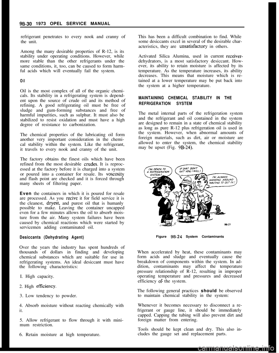
may be upset (Fig. 9B-24).
Figure
98.24 System Contaminants
When accelerated by heat, these contaminants may
form acids and sludge and eventually cause the
breakdown of components within the system. In ad-
dition, contaminants may affect the temperature
pressure relationship of R-12, resulting in improper
operating temperature and pressures and decreased
efficiency
OF the system.
The following general practices should be observed
to maintain chemical stability in the system:
Whenever it becomes necessary to disconnect a re-
frigerant or gauge line, it should be immediately
capped. Capping the tubing will also prevent dirt and
foreign matter from entering.
Tools should be kept clean and dry. This also in-
cludes the gauge set and replacement parts.
Page 545 of 625
98-36 1973 OPEL SERVICE MANUALSPACER
17
RETAINER
RING
c Q
CLUTCHCOIL 8HOUSINGARING TO HEADTAINER RING
SHAFT NUT
CLUTCH DRIVEN
PLATE
BEARING TO PULLEYPULLEY BEARIN
RETAINER RINGCOIL 8HOUSING
CLUTCH DRIVEPLATIRETAINER RING
AND PULLEY ASSEMBLY
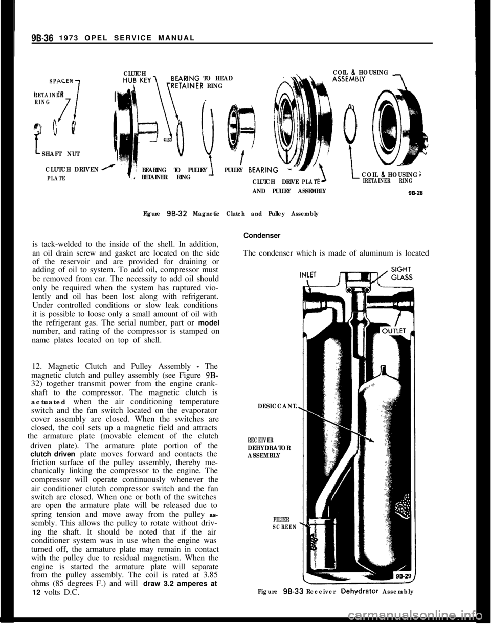
Figure 98-32
Magnetic Clutch and Pulley Assemblyis tack-welded to the inside of the shell. In addition,
an oil drain screw and gasket are located on the side
of the reservoir and are provided for draining or
adding of oil to system. To add oil, compressor must
be removed from car. The necessity to add oil should
only be required when the system has ruptured vio-
lently and oil has been lost along with refrigerant.
Under controlled conditions or slow leak conditions
it is possible to loose only a small amount of oil with
the refrigerant gas. The serial number, part or model
number, and rating of the compressor is stamped on
name plates located on top of shell.
12. Magnetic Clutch and Pulley Assembly
- The
magnetic clutch and pulley assembly (see Figure 9B-
32) together transmit power from the engine crank-
shaft to the compressor. The magnetic clutch is
actuated when the air conditioning temperature
switch and the fan switch located on the evaporator
cover assembly are closed. When the switches are
closed, the coil sets up a magnetic field and attracts
the armature plate (movable element of the clutch
driven plate). The armature plate portion of the
clutch driven plate moves forward and contacts the
friction surface of the pulley assembly, thereby me-
chanically linking the compressor to the engine. The
compressor will operate continuously whenever the
air conditioner clutch compressor switch and the fan
switch are closed. When one or both of the switches
are open the armature plate will be released due to
spring tension and move away from the pulley as-
sembly. This allows the pulley to rotate without driv-
ing the shaft. It should be noted that if the air
conditioner system was in use when the engine was
turned off, the armature plate may remain in contact
with the pulley due to residual magnetism. When the
engine is started the armature plate will separate
from the pulley assembly. The coil is rated at 3.85
ohms (85 degrees F.) and will draw 3.2 amperes at
12 volts D.C.Condenser
The condenser which is made of aluminum is locatedIN:ET
DESICCANT.
RECEIVERDEHYDRATOR
ASSEMBLY
FILTER
SCREEN
Figure 98-33 Receiver Dehydrator Assembly
Page 546 of 625
REFRIGERANT COMPONENTS ALL MODELS
99.37
in front of the radiator so that it receives a high
volume of air flow. Air passing over the condenser
absorbs the heat from the high pressure gas and
causes the refrigerant to condense into a high pres-
sure liquid.Receiver. DehydratorThe receiver-dehydrator is located in the engine
compartment. The purpose of the receiver dehydra-
tor is two fold: the unit insures a solid column of
liquid refrigerant to the expansion valve at all times,
and also absorbs any moisture in the system that
might be present. A bag of desiccant (moisture ab-
sorbing material) is provided to absorb moisture. A
sight glass (see Figure 9B-33) permits visual check-
ing of the refrigerant flow for bubbles or foam. The
continuous appearance of bubbles or foam above an
ambient temperature of 70 degrees F. usually indi-
cates an inadequate refrigerant charge. Bubbles or
foam appearing at ambient temperatures below 70
degrees F. do not necessarily indicate an inadequate
charge and may appear even when the system is
operating properly. A filter screen in the unit pre-
vents foreign material from entering the remainder
of the system.
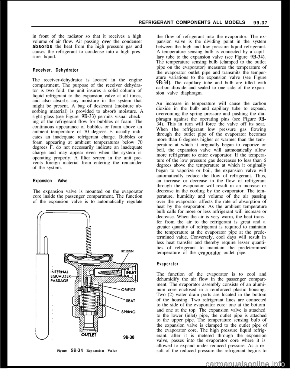
Expansion ValveThe expansion valve is mounted on the evaporator
core inside the passenger compartment. The function
of the expansion valve is to automatically regulate
SCREEN
lLCl98.30
Figure 98-34 Expansion Valvethe flow of refrigerant into the evaporator. The ex-
pansion valve is the dividing point in the system
between the high and low pressure liquid refrigerant.
A temperature sensing bulb is connected by a capil-
lary tube to the expansion valve (see Figure
9B-34).The temperature sensing bulb (clamped to the outlet
pipe on the evaporator) measures the temperature of
the evaporator outlet pipe and transmits the temper-
ature variations to the expansion valve (see Figure
9B-34). The capillary tube and bulb are tilled with
carbon dioxide and sealed to one side of the expan-
sion valve diaphragm.
An increase in temperature will cause the carbon
dioxide in the bulb and capillary tube to expand,
overcoming the spring pressure and pushing the dia-
phragm against the operating pins (see Figure 9B-
34). This in turn will force the valve off its seat.
When the refrigerant low pressure gas flowing
through the outlet pipe of the evaporator becomes
more than 6 degrees higher or warmer than the tem-
perature at which it originally began to vaporize or
boil, the expansion valve will autmotatically allow
more refrigerant to enter evaporator. If the tempera-
ture of the low pressure gas decreases to less than 6
degrees above the temperature at which it originally
began to vaporize or boil, the expansion valve will
automatically reduce the flow of refrigerant. Thus,
an increase or decrease in the flow of refrigerant
through the evaporator will result in an increase or
decrease in the cooling by the evaporator. The tem-
perature, humidity and volume of the air passing
over the evaporator affects the rate of absorption of
heat by the evaporator. As the ambient temperature
bulb calls for more or less refrigerant will increase or
decrease. When the air is very warm, the heat trans-
fer from the air to the refrigerant is great and a
greater quantity of refrigerant is required to maintain
the temperature at the evaporator pipe at the prede-
termined value. Conversely, cool days will result in
less heat transfer and thereby require lesser quanti-
ties of refrigerant to maintain the predetermined
temperature of the evaporator outlet pipe.
EvaporatorThe function of the evaporator is to cool and
dehumidify the air flow in the passenger compart-
ment. The evaporator assembly consists of an alumi-
num core enclosed in a reinforced plastic housing.
Two (2) water drain ports are located in the bottom
of the housing. Two refrigerant lines are connected
to the side of the evaporator core: one at the bottom
and one at the top. The expansion valve is attached
to the lower (inlet) pipe, the outlet pipe is attached
to the upper pipe. The temperature sensing bulb of
the expansion valve is clamped to the outlet pipe of
the evaporator core. The high pressure liquid refrig-
erant, after it is metered through the expansion
valve, passes into the evaporator core where it is
allowed to expand under reduced pressure. As a re-
sult of the reduced pressure the refrigerant begins to
Page 557 of 625
98-48 1973 OPEL SERVICE MANUALCondition3. Compressor being
replaced with a ser-vice replacement
compressor major
oil loss evident.
Amount of Oil Drained
From Compressora. More than 4 oz.Amount of 525 Oil to Install
In Compressor
a.
Same amount as drained from
compressor being replaced.4. Compressor being
rebuilt or repaired
-no major oil loss
evident.b. Less than 4 oz.
a. More than 1
l/2 oz.b. Install 6 oz.
a. Same amount a.s drained from
compressor, plus
1 oz. additional.
5. Compressor being
rebuilt or repaired
major loss of oil
evident.b. Less than 1
l/2 oz.
a. More than 4 oz.b. Install 7 oz.
a. Same amount as drained from
compressor, plus 1
ozadditional.If foreign material is noted in oil drained from sys-
tem or evidence of moisture is obvious in the compo-
nents removed, it is recommended that the entire
system be flushed and the receiver-dehydrator be
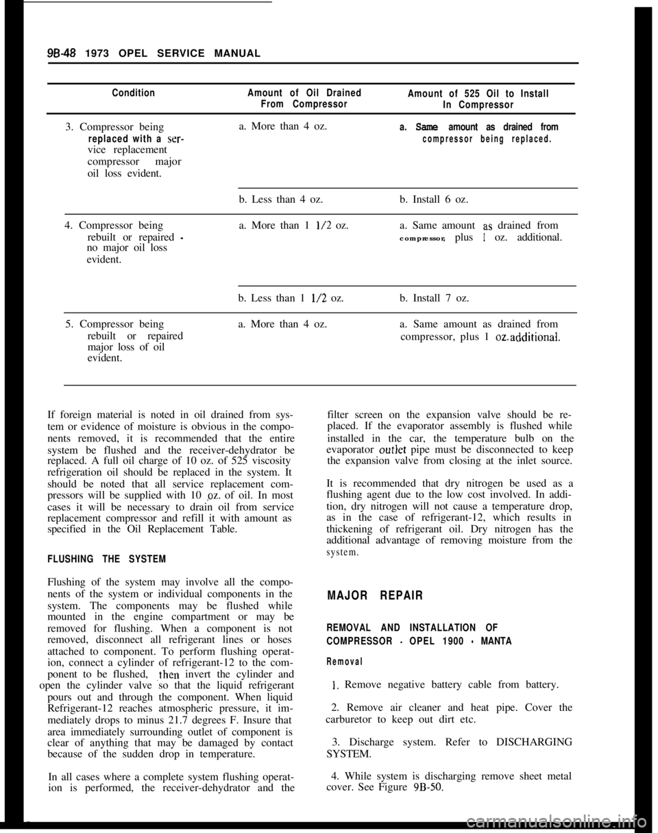
replaced. A full oil charge of 10 oz. of 525 viscosity
refrigeration oil should be replaced in the system. It
should be noted that all service replacement com-
pressors will be supplied with 10 pz. of oil. In most
cases it will be necessary to drain oil from service
replacement compressor and refill it with amount as
specified in the Oil Replacement Table.filter screen on the expansion valve should be re-
placed. If the evaporator assembly is flushed while
installed in the car, the temperature bulb on the
evaporator outlet pipe must be disconnected to keep
the expansion valve from closing at the inlet source.
FLUSHING THE SYSTEMIt is recommended that dry nitrogen be used as a
flushing agent due to the low cost involved. In addi-
tion, dry nitrogen will not cause a temperature drop,
as in the case of refrigerant-12, which results in
thickening of refrigerant oil. Dry nitrogen has the
additional advantage of removing moisture from thesystem.Flushing of the system may involve all the compo-
nents of the system or individual components in the
system. The components may be flushed while
mounted in the engine compartment or may be
removed for flushing. When a component is not
removed, disconnect all refrigerant lines or hoses
attached to component. To perform flushing operat-
ion, connect a cylinder of refrigerant-12 to the com-
ponent to be flushed, ,then invert the cylinder and
open the cylinder valve so that the liquid refrigerant
pours out and through the component. When liquid
Refrigerant-12 reaches atmospheric pressure, it im-
mediately drops to minus 21.7 degrees F. Insure that
area immediately surrounding outlet of component is
clear of anything that may be damaged by contact
because of the sudden drop in temperature.MAJOR REPAIR
REMOVAL AND INSTALLATION OF
COMPRESSOR
- OPEL 1900 - MANTA
Removal
I. Remove negative battery cable from battery.
2. Remove air cleaner and heat pipe. Cover the
carburetor to keep out dirt etc.
3. Discharge system. Refer to DISCHARGING
SYSTEM.
In all cases where a complete system flushing operat-4. While system is discharging remove sheet metal
ion is performed, the receiver-dehydrator and thecover. See Figure
9B-50.
Page 563 of 625

96-54 1973 OPEL SERVICE MANUAL
valve. The filter screen at the inlet port may be re-
placed. Remove screen by threading a lo-32 NF
screw into old filter screen. With a washer and a nut
on the screw arranged to work as a puller screw, hold
the body of the screw and turn the nut. Insert the
new filter screen into the inlet port and lightly tap
screen only enough to seat.
1. Install expansion valve using new o-rings during
installation. Lubricate o-rings prior to installation
using No. 525 viscosity oil.
2. Install evaporator assembly and case attaching
screws. See Figure 9B-70.3. Install blower motor assembly into case and se-
cure with attaching screws. See Figure
9B-69.4. Install finger guard shields and fan housing case.
See Figure
9B-69.5. Install resistor assembly and electrical connector.
Install blower motor connector. See Figure
9B-69.6. Install assembly into car carefully guiding
evaporator pipes up through cowl opening. See Fig-
ure
9B-71.Figure 93-7 1 Inlet and Outlet Pipes and O-Rings
-Opel 1900 Manta
7. Install two (2) upper attaching evaporator at-
taching nuts. See Figures 9B-66 and
9B-67.8. Install two (2) attaching case mounting bracket
to instrument panel screws. See Figure
9B-67.9. Connect two (2) drain hoses underneath evapora-
tor.10. Install evaporator inlet and outlet pipes retainer
and rubber grommet. See Figure
9B-65.11. Connect vacuum cut-off switch and electrical
wiring, making sure the delay restrictor and checkvalve hoses are installed correctly. See Figures
9B-63and 64.
.gB-72 Delay Restrictor and Check Valve Hose.Assembly
12. Install refrigerant hoses and pipes using new
o-rings on line fittings and evacuate system. Refer to
EVACUATING SYSTEM.
13. While system is being evacuated, install in-line
fuse and left side of distributor duct. See Figure 9B-
61.14. Install glove box.
15. Install negative battery cable and charge system.
Refer to CHARGING SYSTEM.
REMOVAL AND INSTALLATION OF CONDENSER
ASSEMBLY -OPEL 1900. MANTA
Removal
1. Remove negative battery cable from battery.
2. Remove air cleaner.
3. Discharge system. Refer to DISCHARGING
SYSTEM.
4. While system is discharging, remove lower radia-
tor hose from radiator and drain coolant into a suita-
ble container.
5. Remove fan shroud.
6. On vehicles with automatic transmission, un-
screw oil lines from connectors on lower radiator
tank and plug lines. It is essential that no dirt enters
the oil lines. When unscrewing oil lines, hold connec-
tors on lower radiator tank with pliers to avoid leak-
ages. Ensure that no dirt enters oil cooler.
7. Remove upper radiator hose from radiator.
8. Remove lower attaching nut and slide radiator
upward and out of engine compartment.
9. Remove inlet and outlet hoses from condenser
Page 570 of 625

REFRIGERANT COMPONENTS ALL MODELS96.61
CAPILLARY T”BEFigure 98.95 Evaporator and Expansion Valve
Assembly GT
valve from refrigerant lines, and tape closed open
ends of lines and inlet and outlet ports of expansion
valve.
Installation5. Install resistor assembly.
6. Install evaporator assembly into car and install
mounting bracket. See Figure
9B-96.Figure 98.96 Evaporator and Blower Assembly
- GT
If expansion valve or refrigerant lines have been ex-
posed to
,the atmosphere for any amount of time and
moisture may have entered the valve or the system,
flush the system and install new receiver-dehydrator
or valve as necessary.7. Untape the refrigerant lines and the inlet and
outlet pipes from the evaporator and install using
new o-rings on line fittings.
Due to the possible adjustment difficulties involved
if the expansion valve is disassembled, disaisembly of
the valve is not recommended. The valve may be
cleaned by submerging it in a bath of trichlorethy-
lene, alcohol, or similar solvent. Dry by blowing iil-tered compressed air through the outlet port of the
valve. The filter screen at the inlet port may be re-
placed. Remove screen by threading a lo-32 NF
screw intp old filter screen. With a washer and a nut
on the screw arranged to work as a puller screw, hold
the body of the screw and turn the nut. Insert the
new filter screen into the inlet port and lightly tap
screen only enough to seat.
1. Install expansion valve using new o-rings during
installation. Lubricate o-rings prior to installation
using No. 525 viscosity oil.
2. Install evaporator assembly and case attaching
screws.
3. Install blower motor assembly into case and se-
cure with attaching screws.
4. Install finger guard shields and fan housing case.Figure 98-97 Refrigerant Hoses and Hose Clamps
Under Car
- GT
Page 581 of 625
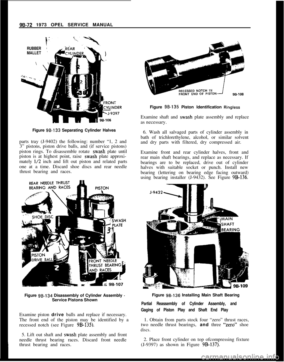
96-72 1973 OPEL SERVICE MANUALRUBBER
MALLET\
Figure 98-133 Separating Cylinder Halves
parts tray (J-9402) the following: number “1, 2 and
3” pistons, piston drive balls, and (if service pistons)
piston rings. To disassemble rotate wash plate until
piston is at highest point, raise wash plate approxi-
mately
l/2 inch and lift out piston and related parts
one at a time. Discard shoe discs and rear needle
thrust bearing and races.
Figure 98-134 Disassembly of Cylinder Assembly
-Service Pistons Shown
Examine piston drive balls and replace if necessary.
The front end of the piston may be identified by a
recessed notch (see Figure
9B-135).5. Lift out shaft and wash plate assembly and front
needle thrust bearing races. Discard front needle
thrust bearing and races.Figure 98-135 Piston Identification
RinglessExamine shaft and wash plate assembly and replace
as necessary.
6. Wash all salvaged parts of cylinder assembly in
bath of trichlorethylene, alcohol, or similar solvent
and dry parts with filtered, dry compressed air.
Examine front and rear cylinder halves, front and
rear main shaft bearings, and replace as necessary. If
bearings are to be replaced, drive out of cylinder
halves with suitable socket or punch. Install new
bearing (lettering on bearing edge facing outward)
using bearing installer (J-9432). See Figure
9B-136.Figure 98.136 Installing Main Shaft Bearing
Partial Reassembly of Cylinder Assembly, and
Gaging of Piston Play and Shaft End Play1. Obtain from parts stock four “zero” thrust races,
two needle thrust bearings, and three “zero” shoe
discs.2. Place front cylinder on top ofcompressing fixture
(J-9397) as shown in Figure
9B-137).
Page 622 of 625

Subject
Page NumbelSubjectPage Number4.Speed Manual I..
Clutch
Detent Cable Adjustment
:Differential
Directional Signal Switch
Repair Opel 1900 & Manta
Repair GT
:Disassembly of
4.Speed Manual Transmission
DistributorFunction of Valves and Hydraulic Control Units
Opel
3.Speed Automatic.................
74-21
Fuse Chart..............................lG-56
Fusible Link.............................
lA-8Specifications.
Point Replacement..
..,78-127A-
17c-9148-73E-393E-4878.23
1C-26
1 c-20
GEGas Tank See Fuel Tank
General Specifications
Engine...............................6A-28
Opel 3.Speed Automatic
.................7C-134
Transmission, Manual.,
..................78-33
Clutch...............................7A-7
Body................................ZA-4
Governor Drive Gear
Opel
3.Speed Automatic.................7C-103
Grille
Opel 1900 & Manta.....................8A-7
GT..................................8A-6 Electrically Heated Rear Window
Engine
General Description
Cooling System
Lubrication System
Trouble Diagnosis
Exhaust Manifold
Exhaust System
Removal and Installation
External Oil Leaks,
Opel 3 Speed Automatic
FFast Idle Adjustment
..................
Filter-Engine Oil
......................
Fluid Checking Procedure Transmission
Opel 3Speed Automatic.............
Frame-Opel 1900 & Manta.............
Frame
GT-Opel......................
SWVOOpel Xipeed Automatic...........
Front Suspension
Opel1900&Manta.................
GT..............................
Front Wheel Alignment................
Front Wheel Bearing Adjustment
All Series.........................
Fuel Gauge
Trouble Diagnosis
Opell$OO&Manta...............
GT............................
Fuel Pump Operation..................
Fuel System
Fuel Tank (Opel 1900 & Manta)
.......
Fuel Lines (Opel 1900 & Manta)
.......
Fuel Tank
(GT)....................
Fuel Gauge Tank Unit
(GT)...........
Fuel Lines
(GT)....................
Fuel Tank Removal and Installation....
Cleaning Tank.....................
lH-576A-268-326A-46A-66A-126D-427C-816E-51
oc-77C~Bl2B-826-77c-1003A-23A-23C-223A-4
HHazard Warning Flasher
....................lG-55
Headlamp Aiming
.........................1 F-46
Headlamp Switch
Opel 190.0 & Manta
.....................1 F-46
Headlamp Mechanism GT
..................8A-2
Heater System Opel 1900 &Manta
Trouble Diagnosis
......................9A-11
Description and Operation
................9A-10
Adjustments and Minor Service............9A-12
Removal and Installation
.................9A-12
Specifications..........................$A-16
Heater System GT
Trouble Diagnosis
......................9A-4
Description and Operation
................9A-2
Adjustments and Minor Service
............9A-4
Removal and Installation.................9A-5
Specifications..........................$A-9Horn
Operation.............................lG-54
Hydraulic Operation
Opel
3.Speed Automatic.................7C-64
IIdentification Number Vehicle...............
OA-1ldle.Adjustment
..........................6E-51
Inflation Pressures, Tires.
...................36-62
Ignition Coil
Specifications.
.........................
lC-26Identification, Engine
......................
OA-1Ignition System
Timing...............................
lC-20Instrument Panel Parts Removal
Page 623 of 625

SubjectPage Number
Subject Page Number
o,,e, 1900 & Manta .....................1H-59
GT..................................lH-63
intake Manifold, 1.9L Engine
..........:.....6A-12
R
Radiator
JRadiator All Models .,.
Radio
66-32
Joint,
Ball
adder.; ...............................3A-7
dower...............................3A-7
K
Antenna Trimmer Adjustment GT
Antenna Trimmer Adjustment
Opel 1900
& Manta
Removal and Installation Opel 1900
& Manta
Removal and Installation GT
Trouble Diagnosis GT
.,.
Trouble Diagnosis -Opel 1900 &Manta
Reverse Clutch
Rings, Piston,
1.9L Engine
Rocker Arm Assembly.
1.9L Engine..
9C-1 06
9C-1 10
Keys and Locks ..........................OA-1
L
Low Servo Cover .........................7c-100
Lubrication
Engine Oil Change Interval ................OC-7
Oil Viscosity Chart. .....................
OC-7
Fluid Capacities........................OC-5
Lubrication System, Engine .................6A-4
9C-1 11
9c-107
9c-105
9c-109
7c-103
6A-19
6A-12
s
M
Mainshaft Assembly 4.Speed
Manual Transmission ....................
78-26
Manifold
Intake ...............................
6A-12
Exhaust ..............................
6A-12
Master
Cdlinder, Brake.....................5A-2
Model
D&ignation (Body Style)
.............. OA-2
Mountings. Engine, GT ....................
28-6
Opel 1900 & Manta
.......................28-6
0
Oil Chan& Interval ........................OC-7
Oil Filter: Engine
.........................OC-7
Oil Flow Circuits, Automatic Transmission .....7C-64
Oil
Pan. Engine ..........................6A-10
Oil Pump Engine.........................
6A-26
Oil Pump Transmission ....................
7C-103
Oil Recommendations Engine. ..............
OC-7
Oil Strainer-Transmission..................7C-99
Oil Viscosity Chart ........................
OC-7
Opel Emission Control System
(OECS)
Specifications..........................6F-64
Service Procedures......................6F-63
Trouble Diagnosis ......................
6F-62
P
Parking Brake............................5C-33
Piston, Pin Rings ..........................
6A~lS
Planetary Gear Set ........................
7C-118
Power Unit Brake ........................
5A-5
Propeller Shaft ...........................
4A-2
Pump, Oil Engine........................
6A-26 Sequence for Transmission Diagnosis
..........
7C-81
Service ProceduresClutch..................7A~5
Shift Linkage Adjustments
4.Speed Manual ........................78-19
3.Speed Automatic .....................7C~93
Shock Absorber, Rear
All Series .............................
3F-51
Spark Plug Specifications ...........................
66-68
Clean &Adjust. ........................
lC-22
Installation............................lC-22
Wires................................lC~21
Specifications
Engine ................................
6A-27
Front Wheel Alignment ....................
3C~22
Speedometer Installation
Opel1900&Manta.....................1 l-68
GT..................................11-70
Spring
Rear SuspensionAll Series ..............
:............3F-52
Front Suspension
Opel 1900
& Manta ...................3A~l6
GTO Opel ..........................
3A15
Starting Motor
Description ............................
1 E-1 0
Specifications .............:............1 B-1 7
Repairs
..................:............18-13
Removal..............................1 B-l 3
Steering Columns
Service Procedures -Opel 1900 &Manta ....
3E-36
Service Procedures
- GT ...._............3E-44
Steering Gear Adjustment. .....
:............3D-27
Steering Gear Disassembly and
Redssembly.....3D-30
Steering Gear Removal and Install&ion ........
30-28
Steering Linkage ..........................
38-19
Suspension
Front................................3A-2
Rear .................................
3F-51
,