alternator OPEL GT-R 1973 Service Manual
[x] Cancel search | Manufacturer: OPEL, Model Year: 1973, Model line: GT-R, Model: OPEL GT-R 1973Pages: 625, PDF Size: 17.22 MB
Page 18 of 625
LUBRICATION AND MAINTENANCE OC-9
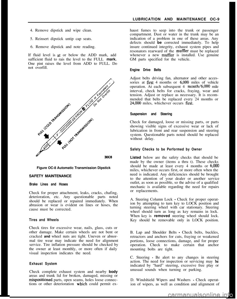
4. Remove dipstick and wipe clean.
5. Reinsert dipstick untip cap seats.
6. Remove dipstick and note reading.
If fluid level is at, or below the ADD mark, add
sufficient fluid to rais the level to the FULL mark.
One pint raises the level from ADD to FULL. Do
not overfill.
3OC8Figure OC-8 Automatic Transmission Dipstick
SAFETY MAINTENANCE
Brake Lines and HosesCheck for proper attachment, leaks, cracks, chafing,
deterioration, etc. Any questionable parts noted
should be replaced or repaired immediately. When
abrasion or wear is evident on lines or hoses, the
cause must be corrected.
Tires and WheelsCheck tires for excessive wear, nails, glass, cuts or
other damage. Make certain wheels are not bent or
cracked and wheel nuts are tight. Uneven or abnor-
mal tire wear may indicate the need for alignment
service. Tire inflation pressure should be checked by
the owner at least monthly, or more often if daily
visual inspection indicates the need.
Exhaust SystemCheck complete exhaust system and nearby body
areas and trunk lid for broken, damaged, missing orm&positioned parts, open seams, holes loose connec-
tions or other deterioration wiuch could permit ex-haust fumes to seep into the trunk or passenger
compartment. Dust or water in the trunk may be an
indication of a problem in one of these areas. Any
defects should be corrected immediately. To help
insure continued integrity, exhaust system pipes and
resonators rearward of the muftler must be replaced
whenever a new mufIler is installed. Use genuine
GM parts specified for the vehicle.
Engine Drive BeltsAdjust belts driving fan, alternator and other acces-
sories at first 4 months or
6,ooO miles of vehicle
operation. At each subsequent 4 month/6,000 mile
interval, check belts for cracks, fraying, wear and
tension. Adjust or replace as necessary. It is recom-
mended that belts be replaced every 24 months or
24,C00 miles, whichever occurs first.
Suspension and SteeringCheck for damaged, loose or missing parts, or parts
showing visible signs of excessive wear or lack of
lubrication in front and rear suspension and steering
system. Questionable parts noted should be replaced
without delay.
Safety Checks to be Performed by OwnerListed below are the safety checks that should be
made by the owner (items a thru t). These checks
should be made at least every 4 months or
6,ooOmiles, whichever occurs first, or more often when the
need is indicated. Any deficiencies should be brought
to the attention of your dealer or another service
outlet, as soon as possible, so the advise of a qualified
mechanic is available regarding the need for repairs
or replacements.
A. Steering Column Lock
_ Check for proper operat-
ion by attempting to turn key to LOCK position and
turning steering wheel with car stationary. Steering
wheel should turn as long as key remains in lock.
When key is removed steering wheel should lock.
Key should be removable only in LOCK position.
B. Lap and Shoulder Belts
- Check belts, buckles,
retractors and anchors for cuts, fraying or weakened
portions, loose connections, damage, and for proper
operation. Check to make certain that anchor
mounting bolts are tight.
C. Steering
- Be alert to any changes in steering
action. The need for inspection or servicing may
beindicated by “hard” steering, excessive free play or
unusual sounds when turning or parking.
D. Windshield Wipers and Washers
- Check operat-
ion of wipers, as well as condition and alignment of
Page 26 of 625
BATTERY AND CABLES - ALL MODELSlA- 5
and terminal connections should not exceed 2/10
volt.
5. Connedt voltmeter positive lead to ground on en-
gine.
At&h prod to voltmeter negative lead and
apply prod to center of battery negative post. Volt-
age drop across the battery ground cable and termi-
nal conne$tions should not exceed 2/10 volt at
200amps.
6. A reading in excess of 2/10 volt when testing
either battery cable indicates excessive resistance in
cable or cpnnections. Clean and tighten cable or con-
nections. Clean and tighten cable terminals
(sub-para. c, below) and recheck for voltage drop. If volt-
age drop Still exceeds 2/10 volt, replace cable with a
genuine Buick-Opel cable to insure ample capacity.
Undercharge Failure of BatteryThe most frequent trouble experienced with storage
batteries is failure to maintain a state of charge suffi-
cient to crank the engine and also furnish current to
the ignitibn system, lights and accessories. Failure to
maintain a proper state of charge may be due to one
or more of the following conditions:
1.
Opertiting Conditions. When determining cause
of premature failure of a battery, consideration must
be given /to the conditions under which the car is
operated.,
In very low temperatures the capacity of a storage
battery
ii considerably reduced and the energy re-
quired f& cranking the. engine is considerably in-
creased. :
Frequent starting, particularly in cold weather,
ac-compani
place in the limited running time. This condition is
aggravated by night driving when lights are turned
on, or by operation of an air conditioner in heavy
traffic.
When thk car is operated under these conditions,adjusting,the voltage regulator to the high limit may
allow enough increase to keep the battery at a safe
state of charge. If the high limit setting does not
maintain a safe state of charge, an occasional booster
charge should be given to the battery.
2. Low charging Rate. In case of premature battery
failure, tbe charging rate of alternator should always
be checked and adjusted if below specifications.
3.
Zntemd Condition The internal condition of the
battery niay be such that it cannot hold a chargesatisfactoiily. Check electrolyte level and test the
battery using the 421 Battery Test.
Overcharge Failure of BatteryA common cause of battery failure is overcharging,
that is, continued input of excessive charging current
after the battery has reached a fully charged condi-
tion.
One evidence that battery is being overcharged is the
need for frequent addition of water to the battery in
order to maintain the electrolyte level above the tops
of the battery separators, since overcharging causes
rapid water loss. When this becomes evident, the
charging rate of alternator should be immediately
checked, as well as the voltage regulator, and ad-
justed to avoid internal damage to battery.
ADJUSTMENTS AND MINOR SERVICEPERIODIC BATTERY INSPECTION AND SERVICE
The battery requires very little attention, but peri-
odic inspection is essential to secure the maximum
efficiency and life. The following services are essen-
tial to maintain the battery at maximum efficiency.
WARNING: Never expose battery to open flame or
electric spark
- battery action generates hydrogen gas
which is flammable and explosive. Do not allow bat-
tery fluid to contact skin, eyes, fabrics or painted
surfaces
- fluidis a sulfuric acid solution which could
cause serious personal injury or property damage.
Wear eye protection when working with battery.
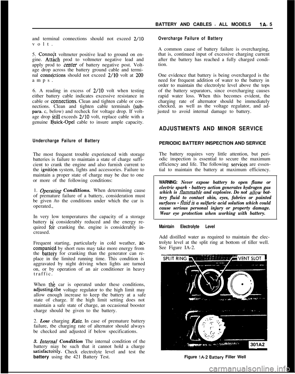
Maintain Electrolyte LevelAdd distilled water as required to maintain the elec-
trolyte level at the split ring at bottom of tiller well.
See Figure IA-2.
Figure lA-2
Battery Filler Well
Page 49 of 625
lD- 28 1973 OPEL SERVldE MANUAL
.CHARG;ING SYSTEM
I
CQNTENTS
Subjyct’
DESCRIPTION
4ND OPERATION‘:
Alternator
. . . . . . . . . . . . . . . . . . . . . . . . . . . . . i . . . . . . . . . . . . . . . . . . . . . . . . . . . . . . . . . . . .\
. . . . . . . . . . . .
Regulator. . . . . . . . . . . . . . . . . . . . . . . . . . . . . . . . . . . . \
. . . . . . . . . . . . . . . . . . , . . . . . . . . . . . . . . . . . \
. . . . . .
DIAGNOSIS: (Not Available):
MAINTENANCE AND ADJUSTMENTS:
Alternator Tests
. . . . . . . . . . . . . . . . . . . . . . . . . . . . . . . . . . . . \
. . . . . . . . . . . . . . . . . . . . . . . . . . . . . .
Regulator Tests. . . . . . . . . . . . . . . . . . . . . . . . . . . . . . . . . . . . \
. . . . . . . . . . . . . . . . . . . . . . . . . . . . . .
MAJOR REPAIR:
Alternator
Removal. . . . . . . . . . . . . . . . . . . . . . . . . . . . . . . . . . . . \
. . . . . . . . . . . . . . . . . . . . . .
Alternator Disassembly. . . . . . . . . . . . . . . . . . . . . . . . . . . . . . . . . . . . \
. . . . . . . . . . . . . . . .
Alternator Reassembly. . . . . . . . . . . . . . . . . . . . . . . . . . . . . . . . . . . . \
. . . . . . . . . . . . . . . .
AlternatorInstallation. . . . . 2 . . . . . . . . . . . . . . . . . . . . . . . . . . . . . . . . . . . .\
. . . . . . . . . . . .
SPECIFICATIONS:
Alternator
. . . . . . . . . . . . . . . . . . . . . . . . . . . . . . . . . . . . \
. . . . . . . . . . . . . . . . . . . . . . . . . . . . . . . . . . . . \
. . . . . . .
Regulator. . . . . 1 . . . . . . . . . . . . . . . . . . . . . . . . . . . . . . . . . . . .\
. . . . . . . . . . . . . . . . . . . . . . . . . . . . . . . . . . . .\
Page No.
1 D-28
1 D-29
1 D-29
1 D-29
1 D-30
lD-31
1 D-34
1 D-35
1 D-35
1 D-35
DESCRIPTION AND OPERATION
ALTERNATOR DESCRIPTION
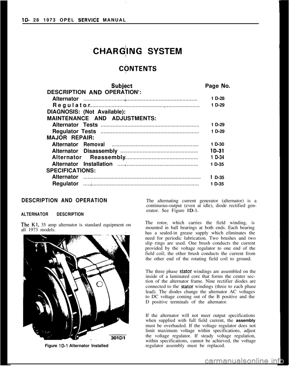
The Kl, 35 amp alternator is standard equipment on
all 1973 models.
Figure lD-1 Alternator Installed
The alternating current generator (alternator) is a
continuous-output (even at idle), diode rectified gen-
erator. See Figure
lD-1.
The rotor, which carries the field winding, is mounted in ball bearings at both ends. Each bearing
has a sealed-in grease supply which eliminates the
need for periodic lubrication. Two brushes and two
slip rings are used. One brush conducts the current
provided by the voltage regulator to one end of the
field coil; the other brush conducts the current from the other end of the rotating field coil to ground.
The three phase
stator windings are assembled on the
inside of a laminated core that forms the center sec-
tion of the alternator frame. Nine rectifier diodes are
connected to the
stator windings (three to each phase
lead). The diodes change the alternator AC voltages
to DC voltage coming out of the B positive and the
D positive terminals of the alternator.
If the alternator will not meet output specifications
when supplied with full field current, the
assembly
must be overhauled. If the voltage regulator does not
limit maximum voltage within specifications, adjust
the voltage regulator. If steady voltage regulation,
within specifications, cannot be achieved, the voltage
regulator assembly must be replaced.
Page 50 of 625
CHARGING SYSTEMlD- 29
REGULAiOR DESCRIPTION
The regulator contains only one unit - a double con-
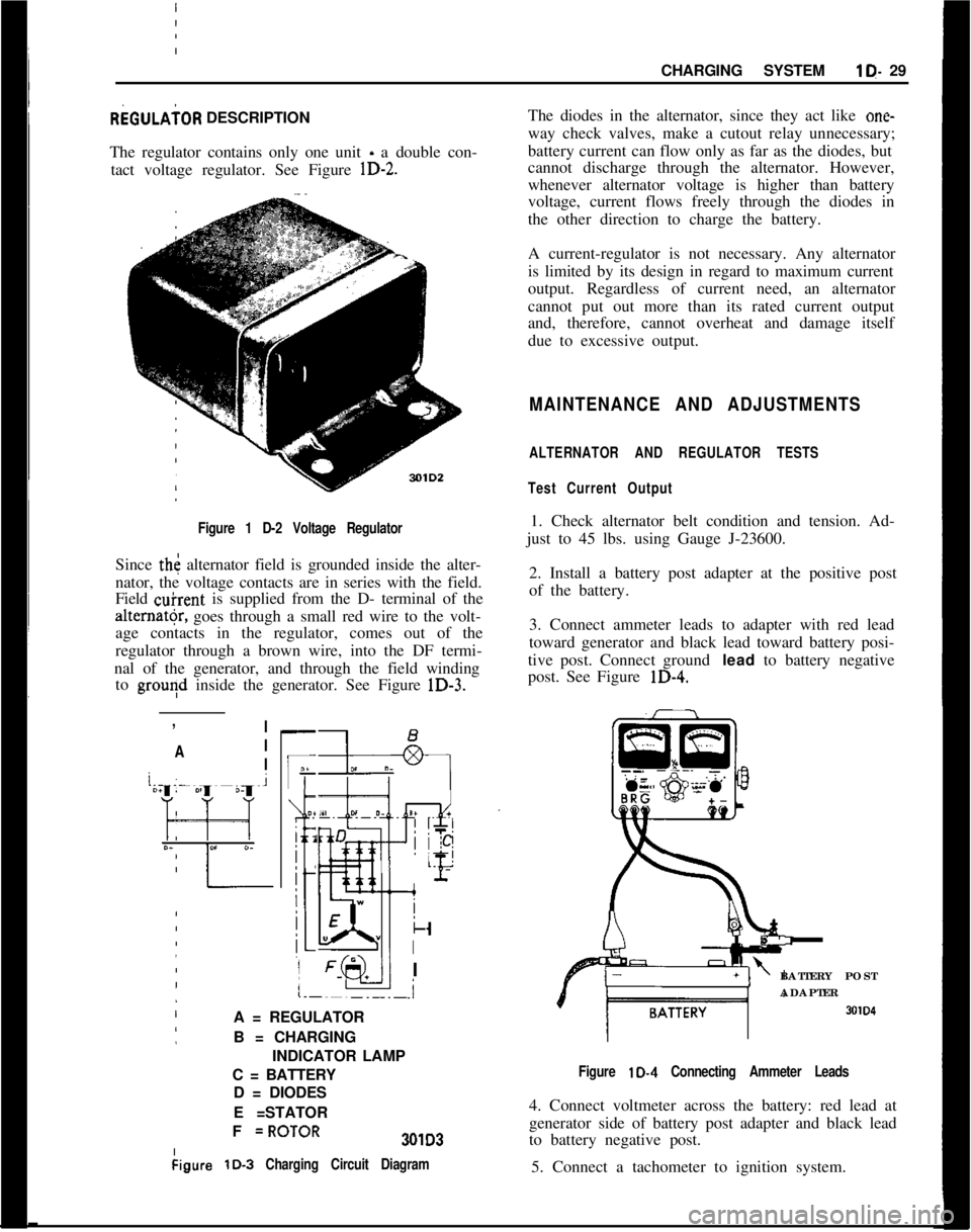
tact voltage regulator. See Figure
lD-2.
I Figure 1 D-2 Voltage Regulator
Since th< alternator field is grounded inside the alter-
nator, the voltage contacts are in series with the field.
Field
&rent is supplied from the D- terminal of the
alter”@, goes through a small red wire to the volt-
age contacts in the regulator, comes out of the
regulator through a brown wire, into the DF termi-
nal of the generator, and through the field winding to
grouqd inside the generator. See Figure lD-3.
:
,
!
/ I
’ A I
j
/ I
-
IF
O?
i 2
j
:
:
k
I
I
.i
A = REGULATOR
B = CHARGING
INDICATOR LAMP
C = BATTERY D = DIODES
E =STATOR
I
I F
=ROTOR301D3
kigure
lD-3 Charging Circuit Diagram
The diodes in the alternator, since they act like one-
way check valves, make a cutout relay unnecessary;
battery current can flow only as far as the diodes, but
cannot discharge through the alternator. However,
whenever alternator voltage is higher than battery
voltage, current flows freely through the diodes in
the other direction to charge the battery.
A current-regulator is not necessary. Any alternator
is limited by its design in regard to maximum current
output. Regardless of current need, an alternator
cannot put out more than its rated current output
and, therefore, cannot overheat and damage itself
due to excessive output.
MAINTENANCE AND ADJUSTMENTS
ALTERNATOR AND REGULATOR TESTS
Test Current Output
1. Check alternator belt condition and tension. Ad-
just to 45 lbs. using Gauge J-23600.
2. Install a battery post adapter at the positive post
of the battery.
3. Connect ammeter leads to adapter with red lead
toward generator and black lead toward battery posi-
tive post. Connect ground
lead to battery negative
post. See Figure
lD-4.
BATTERY POST
ADAPTER
SOID
Figure lD-4 Connecting Ammeter Leads
4. Connect voltmeter across the battery: red lead at
generator side of battery post adapter and black lead
to battery negative post.
5. Connect a tachometer to ignition system.
Page 51 of 625
i
1 D- 301973 OPEL SERVICE MANUAL
6. Make sure all electrical accessories are turned (lff.
Start engine with battery post adapter switch closed;
open switch as soon as engine
iS: started.
7. Adjust engine speed to 2500 RPM.
8. Turn tester control knob to “LOAD” position
aid
adjust knob to obtain highest possible ammeter r&d-
ing. Output must be 30 amperes minimum. If
outcut
is okay, proceed to voltage regulator test below. j
/.9. If output is low, defect may be in alternator or m
regulator. To eliminate regulator, supply field &-
rent direct to cause full alternat,or output. Unplug
three-way connector from regulator and plug in a
jumper between the red and black leads. See Figure
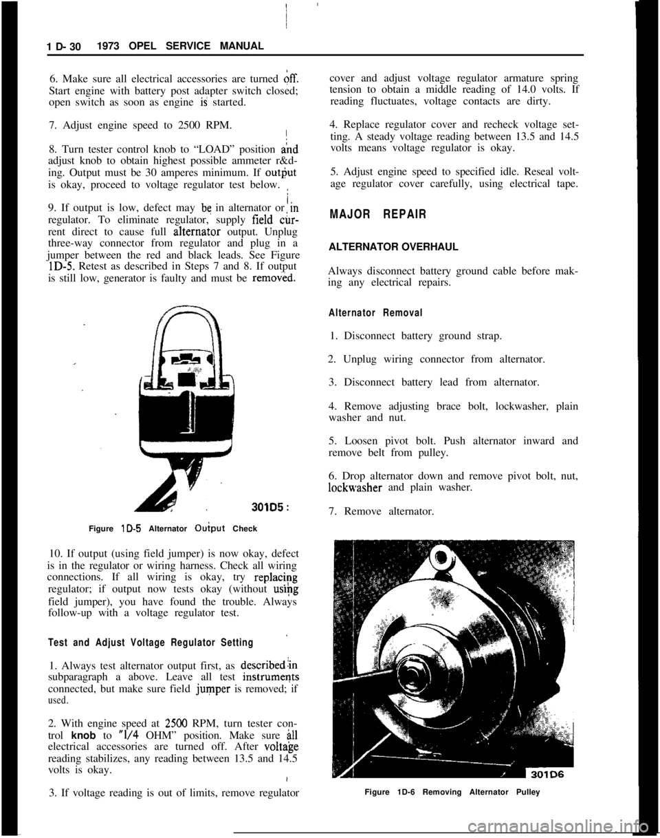
lD-5. Retest as described in Steps 7 and 8. If output
is still low, generator is faulty and must be
remov&d.
301D5 :
Figure lD-5 Alternator Ouiput Check I
10. If output (using field jumper) is now okay, defect
is in the regulator or wiring harness. Check all wiring
connections. If all wiring is okay, try
replac/~g
regulator; if output now tests okay (without
uslpg
field jumper), you have found the trouble. Always
follow-up with a voltage regulator test.
Test and Adjust Voltage Regulator Setting
1. Always test alternator output first, as describedlin
subparagraph a above. Leave all test
instrumeqts
connected, but make sure field
jumper is removed; if
used.
2. With engine speed at 2500 RPM, turn tester con-
trol
knob to “l/4 OHM” position. Make sure ill
electrical accessories are turned off. After volt&e
reading stabilizes, any reading between 13.5 and 14.5
volts is okay.
3. If voltage reading is out of limits, remove regulator cover and adjust voltage regulator armature spring
tension to obtain a middle reading of 14.0 volts. If
reading fluctuates, voltage contacts are dirty.
4. Replace regulator cover and recheck voltage set- ting. A steady voltage reading between 13.5 and 14.5
volts means voltage regulator is okay.
5. Adjust engine speed to specified idle. Reseal volt-
age regulator cover carefully, using electrical tape.
MAJOR REPAIR
ALTERNATOR OVERHAUL
Always disconnect battery ground cable before mak-
ing any electrical repairs.
Alternator Removal
1. Disconnect battery ground strap.
2. Unplug wiring connector from alternator. 3. Disconnect battery lead from alternator.
4. Remove adjusting brace bolt, lockwasher, plain
washer and nut.
5. Loosen pivot bolt. Push alternator inward and
remove belt from pulley.
6. Drop alternator down and remove pivot bolt, nut,
lockwasher and plain washer.
7. Remove alternator.
Figure 1D-6 Removing Alternator Pulley
Page 52 of 625
CHARGING SYSTEMlD- 31
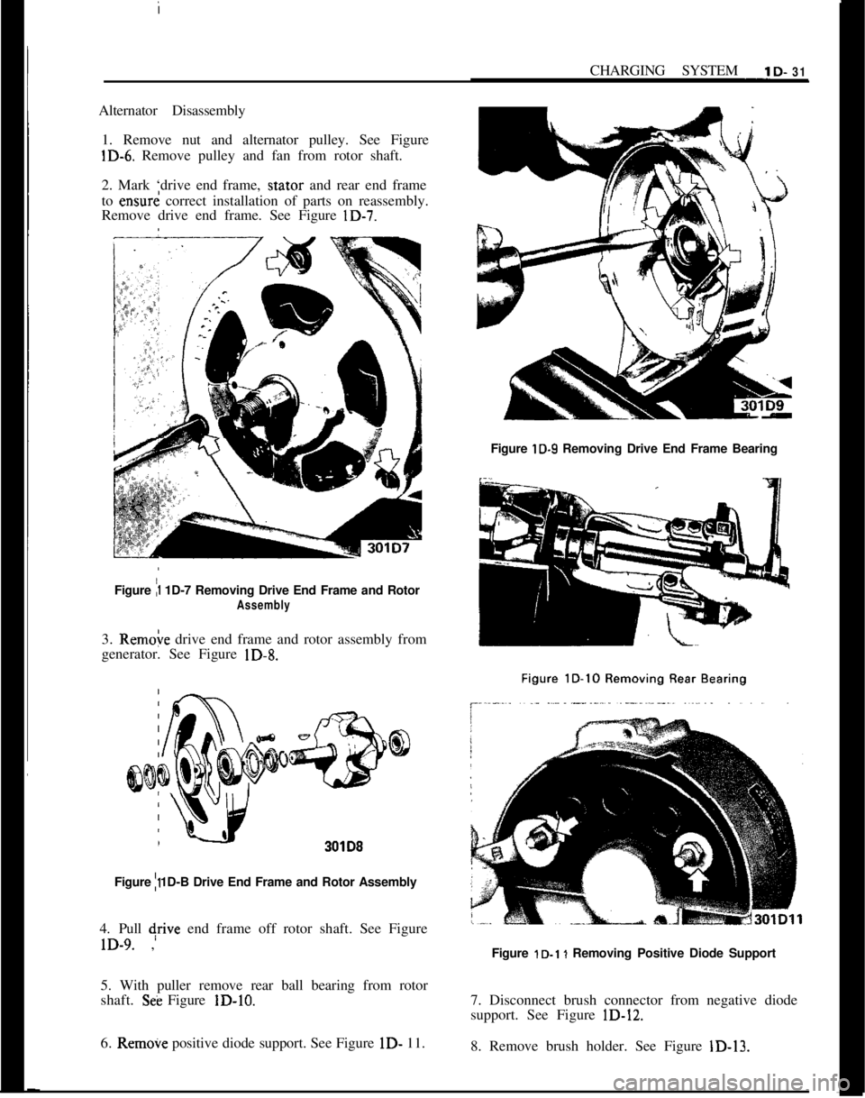
Alternator Disassembly1. Remove nut and alternator pulley. See Figure
lD-6. Remove pulley and fan from rotor shaft.
2. Mark ‘drive end frame,
stator and rear end frame
to
ensurd correct installation of parts on reassembly.
Remove drive end frame. See Figure
lD-7.
Figure lD-9 Removing Drive End Frame Bearing
Figure
/l 1D-7 Removing Drive End Frame and Rotor
Assembly
3. Remoie drive end frame and rotor assembly from
generator. See Figure
lD-8.
/
301D8
Figure I11D-B Drive End Frame and Rotor Assembly
4. Pull +ve end frame off rotor shaft. See Figure
lD-9. ,
5. With puller remove rear ball bearing from rotor
shaft.
S& Figure lD-10.
6.
Remove positive diode support. See Figure lD- 11.
Figure 1D-l 1 Removing Positive Diode Support
7. Disconnect brush connector from negative diode
support. See Figure
lD-12.
8. Remove brush holder. See Figure
lD-13.
Page 54 of 625
CHARGING SYSTEMlD- 33
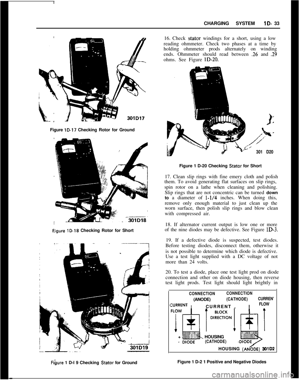
Figure lD-17 Checking Rotor for Ground
Eigure lD-18 Checking Rotor for ShortFibwe 1 D-l 9 Checking Stator for Ground16. Check stator windings for a short, using a low
reading ohmmeter. Check two phases at a time by
holding ohmmeter prods alternately on winding
ends. Ohmmeter should read between
.26 and .29ohms. See Figure lD-20.
301 D20Figure 1 D-20 Checking Stator for Short
17. Clean slip rings with fine emery cloth and polish
them. To avoid generating flat surfaces on slip rings,
spin rotor on a lathe when cleaning and polishing.
Slip rings that are not concentric can be turned down
to a diameter of
l-1/4 inches. When doing this,
remove only enough material to just clean up the
worn surface, then polish slip rings and blow clean
with compressed air.
18. If alternator current output is low one or more
of the nine diodes may be defective. See Figure lD-3.
19. If a defective diode is suspected, test diodes.
Before testing diodes, disconnect them, otherwise it
is not possible to determine which diode is defective.
Use a test light supplied with a DC voltage of not
more than 24 volts.
20. To test a diode, place one test light prod on diode
connection and other on diode housing, then reverse
test light prods. Test light should light brightly in
,
CONNECTIONCONNECTION
I(ANODE)
(CATHODE)
IURRENTCURRENT ,I
CURREN’
FLOW+
+ HOUSING(CATHODE)HOUSING
(AN&E) 3lMD2Figure 1 D-2 1 Positive and Negative Diodes
Page 55 of 625
1 D- 34 1973 OPEL SERVICE MANUAL!
I
one direction, but should not light at all in the otlier
direction. Diodes in each set of three should p&s
current and block current in the ‘same directions
Asthe others in the set. See Figure lD-21.
Removing Diodes/
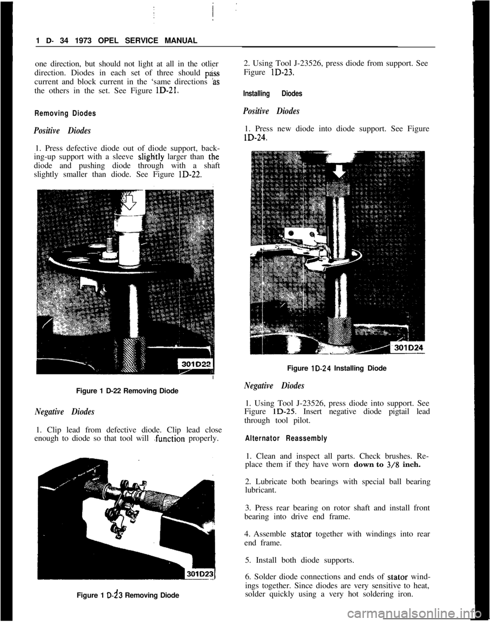
Positive Diodes1. Press defective diode out of diode support, back-
ing-up support with a sleeve sliglitly larger than the
diode and pushing diode through with a shaft
slightly smaller than diode. See Figure lD-22.;
Figure 1 D-22 Removing Diode
Negative Diodes1. Clip lead from defective diode. Clip lead close
enough to diode so that tool will .function properly.
Figure 1 D-d3 Removing Diode2. Using Tool J-23526, press diode from support. See
Figure lD-23.
Installing Diodes
Positive Diodes1. Press new diode into diode support. See FigurelD-24.
Figure lD-24 Installing Diode
Negative Diodes1. Using Tool J-23526, press diode into support. See
Figure lD-25. Insert negative diode pigtail lead
through tool pilot.
Alternator Reassembly1. Clean and inspect all parts. Check brushes. Re-
place them if they have worn down to
3/8 inch.
2. Lubricate both bearings with special ball bearing
lubricant.
3. Press rear bearing on rotor shaft and install front
bearing into drive end frame.
4. Assemble stator together with windings into rear
end frame.
5. Install both diode supports.
6. Solder diode connections and ends of stator wind-
ings together. Since diodes are very sensitive to heat,
solder quickly using a very hot soldering iron.
Page 56 of 625
CHARGING SYSTEMlD- 35
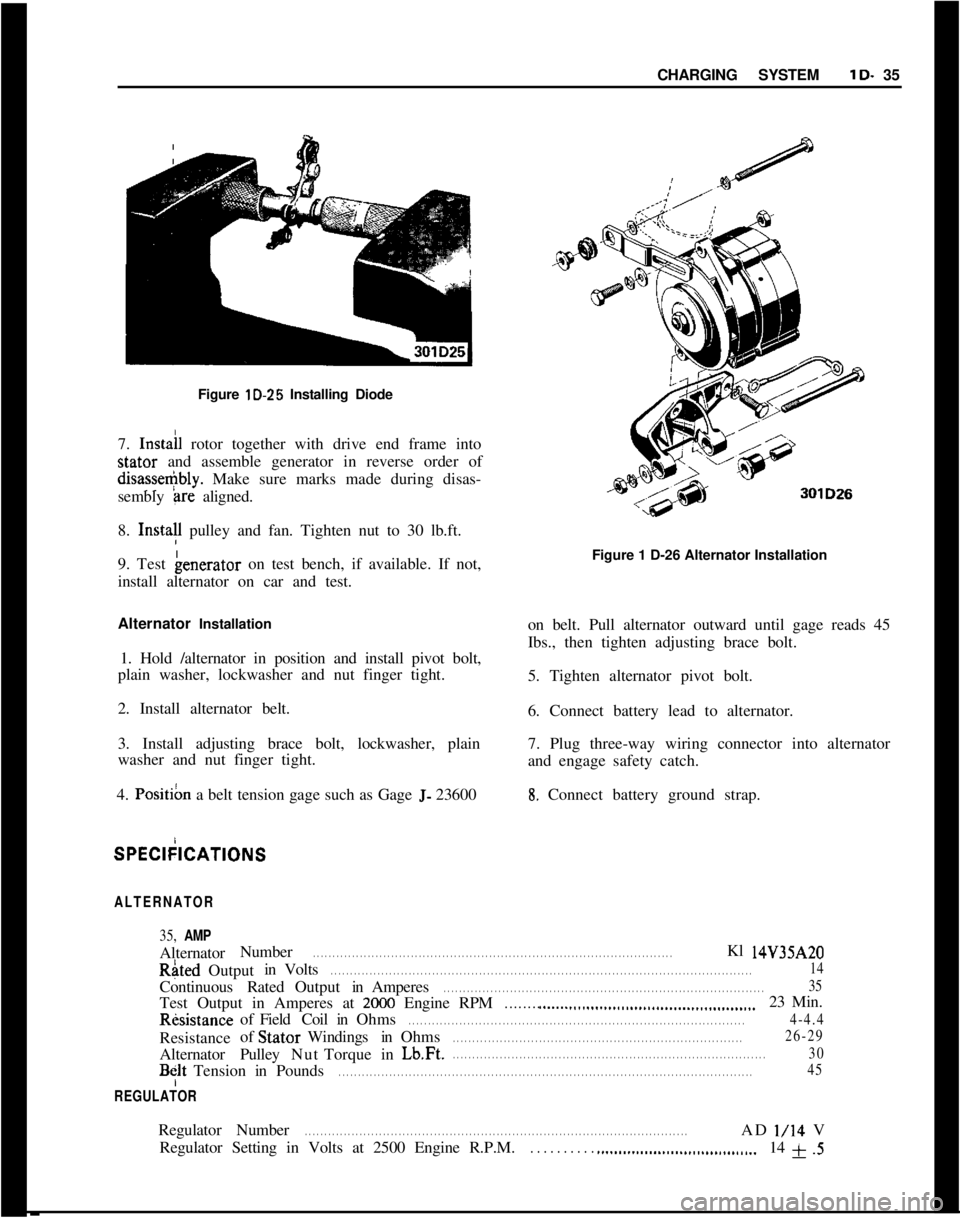
’Figure lD-25 Installing Diode
I
7. Instail rotor together with drive end frame intostator and assemble generator in reverse order ofdisasse+bly. Make sure marks made during disas-
sembly
+-ire aligned.
8. Insta!l pulley and fan. Tighten nut to 30 lb.ft.
9. Test benerator on test bench, if available. If not,
install alternator on car and test.
Alternator Installation
1. Hold /alternator in position and install pivot bolt,
plain washer, lockwasher and nut finger tight.
2. Install alternator belt.
3. Install adjusting brace bolt, lockwasher, plain
washer and nut finger tight.
4.
Posit& a belt tension gage such as Gage J- 23600Figure 1 D-26 Alternator Installation
on belt. Pull alternator outward until gage reads 45
Ibs., then tighten adjusting brace bolt.
5. Tighten alternator pivot bolt.
6. Connect battery lead to alternator.
7. Plug three-way wiring connector into alternator
and engage safety catch.8. Connect battery ground strap.SPECkICATIONS
ALTERNATOR
35, AMPAlternatorNumberRated
. . . . . . . . . . . . . . . . . . . . . . . . . . . . . . . . . . . . . . . . . . . . . . . . . . . . . . . . . . . . . . . . . . . . . . . . . . . . . . . . . . . . . . . . . . . .Kl 14V35AZOOutputinVolts
. . . . . . . . . . . . . . . . . . . . . . . . . . . . . . . . . . . . . . . . . . . . . . . . . . . . . . . . . . . . . . . . . . . . . . . . . . . . . . . . . . . . . . . . . . . . . . . . . . . . . . . . . . . .14ContinuousRatedOutputinAmperes
. . . . . . . . . . . . . . . . . . . . . . . . . . . . . . . . . . . . . . . . . . . . . . . . . . . . . . . . . . . . . . . . . . . . . . . . . . . . . . . . . .35Test Output in Amperes at
2000 Engine RPM. . . . . . . . ..__.._...........................................23 Min.RksistanceofFieldCoilinOhms
. . . . . . . . . . . . . . . . . . . . . . . . . . . . . . . . . . . . . . . . . . . . . . . . . . . . . . . . . . . . . . . . . . . . . . . . . . . . . . . . . . . . . .4-4.4Resistanceof StatorWindingsinOhms
. . . . . . . . . . . . . . . . . . . . . . . . . . . . . . . . . . . . . . . . . . . . . . . . . . . . . . . . . . . . . . . . . . . . . . . . . .26-29AlternatorPulleyNutTorqueinLb.Ft.
. . . . . . . . . . . . . . . . . . . . . . . . . . . . . . . . . . . . . . . . . . . . . . . . . . . . . . . . . . . . . . . . . . . . . . . . . . . . . . . .30
BfltTensioninPounds. . . . . . . . . . . . . . . . . . . . . . . . . . . . . . . . . . . . . . . . . . . . . . . . . . . . . . . . . . . . . . . . . . . . . . . . . . . . . . . . . . . . . . . . . . . . . . . . . . . . . . . . . .45
REGULATORRegulatorNumber
. . . . . . . . . . . . . . . . . . . . . . . . . . . . . . . . . . . . . . . . . . . . . . . . . . . . . . . . . . . . . . . . . . . . . . . . . . . . . . . . . . . . . . . . . . . . . . . . . .ADl/14V
Regulator Setting in Volts at 2500 Engine R.P.M.
. . . . . . . . . . ..___................................14 f .5
Page 57 of 625
I
;
I
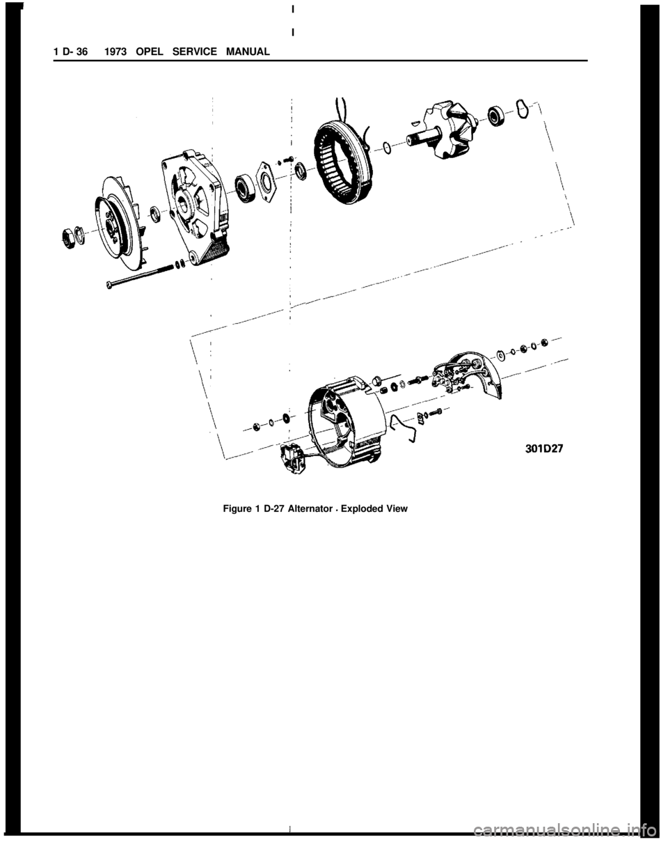
1 D- 361973 OPEL SERVICE MANUALI‘\
Figure 1 D-27 Alternator - Exploded View301D27