ignition OPEL GT-R 1973 Service Manual
[x] Cancel search | Manufacturer: OPEL, Model Year: 1973, Model line: GT-R, Model: OPEL GT-R 1973Pages: 625, PDF Size: 17.22 MB
Page 10 of 625
GENERAL INt=ORMATION OA-1
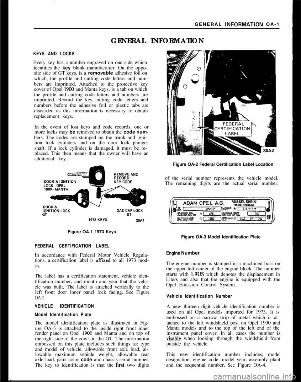
GENERAL INFORMATIONKEYS AND LOCKSEvery key has a number engraved on one side which
identities the key blank manufacturer. On the oppo-
site side of GT keys, is a removable adhesive foil on
which, the profile and cutting code letters and num-
bers are imprinted. Attached to the protective key
cover of Opel
1900 and Manta keys, is a tab on which
the profile and cutting code letters and numbers are
imprinted. Record the key cutting code letters and
numbers before the adhesive foil or plastic tabs are
discarded as this information is necessary to obtain
replacement keys.
In the event of lost keys and code records, one or
more locks may be removed to obtain the code num-
bers. The codes are stamped on the trunk and igni-
tion lock cylinders and on the door lock plunger
shaft. If a lock cylinder is damaged, it must be re-
placed. This then means that the owner will have an
additional key.REMOVE ANDDOOR &
IGNIKEY CODELOCK. OPELIGNITION
LOCKGAS CAP LOCKGTGT
Figure OA-1 1973 Keys
FEDERAL CERTIFICATION LABELIn accordance with Federal Motor Vehicle Regula-
tions, a certification label is
affIxed to all 1973 mod-
els.The label has a certification statement, vehicle iden-
tification number, and month and year that the vehi-
cle was built. The label is attached vertically to the
left front door inner panel lock facing. See Figure
OA-2.
VEHICLE IDENTIFICATION
Model Identification PlateThe model identification plate as illustrated in Fig-
ure OA-3 is attached to the inside right front inner
fender panel on Opel
1900 and Manta and on top of
the right side of the cowl on the GT. The information
embossed on this plate includes such things as; type
and model of vehicle, allowable front axle load, al-
lowable maximum vehicle weight, allowable rear
axle load, paint color code and chassis serial number.
The key to identification is that the first two digitsFigure OA-2 Federal Certification Label Location
of the serial number represents the vehicle model.
The remaining digits are the actual serial number.
Figure OA-3 Model Identification Plate
Engine Number
The engine number is stamped in a machined boss on
the upper left center of the engine block. The number
starts with 1.9US which denotes the displacement in
Liters and also that the engine is equipped with the
Opel Emission Control System.
Vehicle Identification NumberA new thirteen digit vehicle identification number is
used on all Opel models imported for 1973. It is
embossed on a narrow strip of metal which is at-
tached to the left windshield post on Opel 1900 and
Manta models and to the top of the left end of the
instrument panel cover. In all cases the number isvisable when looking through the windshield from
outside the vehicle.
This new identification number includes; model
designation, engine code, model year, assembly plant
and the sequential number. See Figure OA-4.
Page 19 of 625
CC-10 1973 OPEL SERVICE MANUAL
wiper blades. Check amount and direction of fluid
sprayed by washers during use.,
E. Defrosters - Check performance by moving con-
trols to “DEF” and noting
am$nmt of air directed
against the windshield.
I
F. Wheel Alignment and
Balabce - In addition to
abnormal tire wear, the need fbr wheel alignment
service may be indicated by a pull to the right or
!eftwhen driving on a straight and level road. The need
for wheel balancing is usually
iddicated by a vibra-
tion of the steering wheel or
se;+ tihile driving at
normal highway speeds.I
IG. Brakes
- Be alert to illumiriation of the brake
warning light or changes in braking action,
SUCK as
repeated pulling to one side, unusual sounds when
braking or increased brake pedal travel. Any of thesecould indicate the need for
brakk system inspection
and/or service.
H. Parking Brake and Transmission “PARK”
Mechanism
- Check parking brake holding ability by
parking on a fairly steep hill and restraining the vehi-
cle with the parking brake only.
eon cars with auto-
matic transmissions, check the holding ability of the
“PARK” mechanism by releasing all brakes after
the transmission selector lever hak been placed in the“P” position.
I. Glass
- Check for broken, scrritched, dirty or da-
maged glass on vehicle that
coulld obscure vision’or
become an injury hazard.
J. Lights and Buzzers
- Check all instrument panel
illuminating and warning lights,’ seat belt reminder
light and buzzer, ignition key
b&er, interior lights,
license plate lights, side marker! lights, headlamps,
parking lamps, tail lamps, brake lights, turn signals,
backup lamps, and hazard warding flashers. Have
someone observe operation of
&ach exterior light
while you activate the controls: The operation of
instrument panel warning lights is covered in the
“Starting and Operating“ section of your
Own&%
Manual.K. Transmission Shift Indicator
‘- Check to be sure
automatic transmission shift
indiCator accurately i”-
dicates the shift position selected.
I
CAUTION: Before making thk check below,I
be sure to have a clear dist&e ahead and:
behind the car, set the parking brake and
firmly apply the foot brake.
Do not depress
accelerator pedal. Be prepared to
turn off ’
ignition switch
immediat+y if engine
should start.L. Starter Safety Switch (Automatic Transmissibn
Cars)
- Check starter safety switch by placing the
transmission in each of the driving gears while
at-tempting to start the engine. The starter should oper-ate only in the Park (“P”) or Neutral (“N”)
positions.
M. Horn
- Blow the horn occasionally to be sure thatit works. (Ignition switch must be in the “ON” posi-
tion.)
N. Seat Back Latches
- Check to see that seat back
latches are holding by pulling forward on the top of
each folding seat back.
0. Rearview Mirrors and Sun Visors
- Check that
friction joints are properly adjusted so mirrors and
sun visors stay in the selected position.
P. Door Latches
- Check for positive closing, latch-
ing and locking.
Q. Hood Latches - Check to make sure hood closesfirmly by pressing on the hood at the latching point
after each closing. Check also for broken, damaged
or missing parts which might prevent secure latch-
ing.R. Fluid Leaks
- Check for fuel, water, oil or other
fluid leaks by observing the ground beneath the vehi-cle after it has been parked for a while. If gasoline
fumes or fluid are noticed at any time, the cause
should be determined and corrected without delay
because of the possibility of fire.
S. Exhaust System
- Be alert to any change in the
sound of the exhaust system or a smell of fumes
which may indicate a leak.
Head Restraints
- Check that no head restraint
components are missing, damaged or loose. (Does
not apply to GT Models).
Disc BrakesCheck brake pads and condition of rotors while
wheels are removed during tire rotation. (Note belowregarding more frequent checks also applies to disc
brakes.)
Parking and Drum BrakesCheck drum
brake linings and other internal brake
components at each wheel (drums, wheel cylinders,
etc.). Parking brake adjustment also should be
checked whenever drum brake linings are checked.
NOTE: More frequent checks should be
made if driving conditions a.nd habits result
in frequent brake application. When brakes
require relining, it is recommended thatyou use those genuine General Motors
parts specified for your car,and Delco fluid
as required.
Page 22 of 625

ELECTRICALGROUP 1
Section
IAIBICIDIE
IFIGIH
II
IJTitle
Battery and Cables. . . . . .
StartingSystem. . . . . . . . . . . .
Ignition System, .
ChargingSystemWashers and Wipers
.,
LightingSystems
SignalSystems
instrument Panel.........
Gauges...........................Wiring Circuit Diagram:
Page No.
lA- 2lB-10lC-18
1 D-28
1 E-37
1 F-45
1 G-54
1 H-57
1 l-65
1 J-72
Page 31 of 625
1 B- 101973 OPEL SERVICE #MANUAL
STARTlhG SYSTEM
/
ALL
MODEILS
CONTENTS
Subject
DESCRIPTION AND OPERATION:
Starting SystemDescription
. . . . . . . . . . . . . . . . . . . . . . . . . . . . . . . . . . . . \
. . . . . .
DIAGNOSIS:
Starting System Diagnosis,
. . . . . . . . . . . . . . . . . , . . . . . . . . . . . . . . . . . . \
. . . . . . . .
MAINTENANCE AND ADJUSTMENTS:Starting System
Checks. . . . . . . . . . . . . . . . . . . . . . . . . . . . . . . . . . . . \
. . . . . . . . . . . . . .
MAJOR REPAIR:
Removal. . . . . . . . . . . . . . . . . . . . . . . . . . . . . . . . . . . . \
. . . . . . . . . . . . . . . . . ., . . . . . . . . . . . . . . . . . . . . . . . . . .
Disassembly. . . . . . . . . . . . . . . . . . . . . . . . . . . . . . . a.... . . . . . . . . . . . . . . . . . . . . . . . . . . . . . . . . . . . .\
CleaningandInspecting Parts. . . . . . . . . . . . . . . . . . . . . . . . . . . . . . . . . . . . \
. .
Replacing Field Coils. . . . . . . . . . . , . . . . . . . . . . . . . . . . . . . . . . . . \
. . . . . . . . . . . . . . . . . . . .
Checking and Replacing Brushes. . . . . . . . . . . . . . . . . . . . . . . . . . . . . . . .
Replacing Bushings. . . . . . . . . . . . . . . . . . . . . . . . . . . . . . . , . . . . \
. . . . . . . . . . . . . . . . . . . . . .
Assembly. . . . . . . . . . . . . . . . . . . . . . . . . . . . . . . . . . . . \
. . . . . . . . . . . . . . . . . . . . . . . . . . . . . . . . . . . . \
. . . . . .
Installation. . . . . . . . . . . . . . . . . . . . . . . . . . . . . . . . . . . . \
. . . . . . . . . . . . . . . . . . . . . . . . . . . . . . . . . . . . \
. . . .
SPECIFICATIONS:
Starter Specifications
. . . . , . , . . . . . . . . . . . . . . . . . . . . . . . . . . . . . . . . . . . . . . . . . . . . . . .
Page No.
lB-10
16-10
18-12
18-13
18-13
18-14
18-14
16-15
18-16
lB-16
18-17
18-17
DESCRIPTION AND OPERATION
STARTING SYSTEM DESCRlPTlqN
The new Delco Remy starter for 1973 is a brush-
type series wound electric motor equipped with an
overrunning clutch and operated by a
soienoid. The
field frame is enclosed by the commutator end frame
and the drive housing and carries the pole shoes and
the
field coils. The armature has a spline on the drive
end which carries the over-running clutch and pinion
assembly. The armature shaft is supported in
sin-
tered bronze bushings in the commtitator end frame
and the drive end housing. These bushings are
packed with lubricant during initial assembly
and
TROUBLE DIAGNOSIS ’
STARTING SYSTEM DIAGNOSIS/
require no additional lubrication between overhaul
periods.
As the starter is operated by turning the ignition
switch on the instrument panel, the shift lever is
moved against spring tension. By means of the guide
ring, the shift lever moves the pinion into mesh with
the flywheel ring gear.
After the pinion meshes with the flywheel ring gear
teeth, the solenoid contact disc closes the circuit and
the engine is cranked. When the engine starts, the
speed of the rotating flywheel causes the pinion to
over-run the clutch and armature. The pinion con-
tinues to be engaged as long as the shift lever is kept
in the cranking position.
In case of cranking motor breakdown, it should be kept in mind that the
relevant cause(s) for the trouble may not only lie in the cranking mot\
or itself
Page 32 of 625
I
STARTING SYSTEMlB- 11
but also in the condition of related units, such as battery, switches, electrical
wiring and wiring connections.
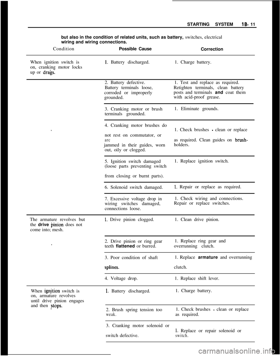
ConditionPossible Cause
Correction
When ignition switch is1. Battery discharged.1. Charge battery.
on, cranking motor locks
up or
dra’gs.2. Battery defective.1. Test and replace as required.
Battery terminals loose,Retighten terminals, clean battery
corroded or improperlyposts and terminals and coat them
grounded.with acid-proof grease.
3. Cranking motor or brush1. Eliminate grounds.
terminals grounded.
I
4. Cranking motor brushes do
,
1. Check brushes
- clean or replace
not rest on commutator, or
arcas required. Clean guides on brush-
jammed in their guides, wornholders.
out, oily or clogged.
5. Ignition switch damaged1. Replace ignition switch.
(loose parts preventing switch
I
from closing or burnt parts).
6. Solenoid switch damaged.
1. Repair or replace as required.
7. Excessive voltage drop in1. Check wiring and connections.
wiring switches damaged,Repair or replace switches.
connections loose.
The armature revolves but
1. Drive pinion clogged.1. Clean drive pinion.
the drive binion does not
come into; mesh.
2. Drive pinion or ring gear1. Replace ring gear and
,
teeth flattened or burred.overrunning clutch.
I
3. Poor condition of shaft1. Replace armature and overrunningsplines.clutch.
4. Voltage drop.1. Replace shift lever.
When ignjtion switch is
1. Battery discharged.1. Charge battery.
on, armature revolves
until drive pinion engages
and then
Btops.2. Brush spring tension too1. Check brushes - clean or replace
weak.as required.
3. Cranking motor solenoid or
1. Replace or repair solenoid or
switch defective.
switch.
Page 33 of 625
19- 12 1973 OPEL SERVICE MANUAL :ConditionPosiible CauseCorrection4. Voltage drop.1. Check wiring and wiring
connections.
5. Overrun&g clutch slips.1. Replace overrunning clutch.
The cranking motor keeps
on rotating after ignition
switch is off.1. Ignition
{witch does not
cut off or solenoid switch
sticks.
1, Immediately disconnect cranking
motor cable from battery. Inspect
and/or replace or repair ignition and
solenoid switches as required.
The drive pinion does notdemesh after engine has
been cranked.1. Drive pinion or ring gear
1. Clean components as specified.
teeth clogged or flattened.Replace as required.
Return spring slack or broken.MAlNTEilANCE AND ADJUSTMENT
/
STARTING SYSTEM CHECKS
Voltage Loss ChecksWhen the starter cranks too slowly, check the bat-
tery state of charge and all electrical connections
between the battery and starter.
1. Turn on headlights and
opera’te starter. If head-
lights dim considerably when starter is engaged, the
battery may be discharged or be defective. Check the
battery.
2. If the headlights stay bright but the starter d&s
not turn over, the starter cables may be faulty or the
starter defective.
(a) Test battery voltage while cranking engine
1(9volts minimum).
(b) Check voltage from starter tkrminal of solenoid
to starter frame while cranking engine.
3. The difference in readings taken in Operations 2a
and 2b above represents the
volt& drop through the
cables and solenoid switch. Voltdge drop should
Gotexceed
.5 volt.
4. Locate excessive resistance as follows:
(a) Turn voltmeter to scale above 12 volts and con-
nect voltmeter leads
across connection or switch: to
be checked.
(b) With starter switch closed, turn voltmeter switch
to lowest scale and take reading as quickly as possi-
ble, then turn switch back to higher scale and stop
cranking engine.(c) Voltmeter must not read more than
.2 volt across
any
c:onnection. If voltmeter reads more than .2 volt,
the
d~efect must be corrected.
Starter Current Draw - Lock Test1. Make sure battery is fully charged and in good
condition.
2. Connect a volt ampere starter tester according to
manufacturer’s instructions.
3. Pull parking brake on securely, shift transmission
into 4th (direct) gear and actuate starter. (Starter will
not
t,urn engine because engine is locked through
transmission.)
4. While starter is actuated, read voltage and current.
Refer to Specification Chart.
(a) Voltage low
_ poor battery or a voltage loss in the
starter circuit.
(b) Current high
- short circuit in starter. Overhaul
starter.
(c) Current low
- commutator dirty, brushes worn,
solenoid switch contacts defective or open circuit in
starter. Overhaul starter.
Starter Current Draw. On Car1. Bring engine to normal operating temperature.
2. Stop engine and disconnect coil wire from dis-
tributor.
3. Ground coil wire to prevent excessive coil voltage
build up.
Page 39 of 625
1 C- 18 1973 OPEL SERVICE MANUAL
IGNITIPN SYSTEM
CbNTENTS
Subject
DESCRIPTION AND OPERATION: Ignition System ..................................................................
Ignition
Switc,h....................................................................
Ignition Coil
..........................................................................\
Distributor
............................I...............................................
DIAGNOSIS: (Not Available)
MAINTENANCE AND ADJUSTMENTS: Contact PointReplacement ............................................
Dwell Angle Adjustment :
................................................
Ignition Timing Adjustment ..........................................
Ignition Wire Inspection :
..................................................
Check Ignition Output ......................................................
Check Distributor
..............................................................
Check Spark Plugs
............................................................
MAJOR REPAIR: Distributor Removal ..........................................................
Disassembly ........................
I...............................................
Reassembly
..........................I...............................................
Distributor Installation
....................................................
SPECIFICATIONS: /
Ignition
Coil ..........................................................................
Distributor
....‘........................i...............................................
Spark Plugs ........................................................................\
..
DESCRIPTION AND OPERATION
INGITION SYSTEM
The ignition system basically consists of an ignitipn
switch, ignition coil, distributor, battery and related
wiring. The ignition switch is located in the steering
column, the ignition coil is located left front inner fender
skirt and the distributor is located at the left
front of the engine.
IGNITION SWITCH
The combined ignition switch and steering lock ian
be switched to any one of the below listed positions.
Insert key with notch pointing upward.
Page No.
lC-18
lC-18
lC-19
lC-19
1 c-20
1 c-20
1 c-20
lC-21 r
lC-21
1 c-22
1 c-22
1 r-23
1 C-23
1 c-24
1 C-25
1 C-26
1 C-26
1 C-26
(Fully counterclockwise) Lock position. Ignition
locked, steering locked, only with key removed.
Electrical circuits disconnected except to main light-
ing switch and dome lamp. The
key can be removed.
0- (First position clockwise from lock) Garage posi-
tion. ‘The key and lock assembly must be pushed “in”
to reach this position from lock. The steering is un-
locked and the ignition is off. The electrical circuits
are the same as in lock position. The key cannot be withdrawn.
l- [Chposition.) All electrical circuits controlled by
ignition switch are completed through the switch.
The key cannot
be removed while switch is in drive
position.
Page 40 of 625
IIIGNITION SYSTEMlC- 19
11. (Startx position.) The ignition key must be
released as soon as engine starts. The switch then
returns aujomatically to the on position.
IGNITION
GOILThe ignition coil consists of a laminated non- mag-
netic iron
(core enclosed by two coils; the primary
winding and the secondary winding.
The prim+y circuit consists of the power source
(battery), the ignition switch, the ignition coil pri-
mary winding, the distributor breaker points with
ignition condenser connected in parallel, and all con-
necting
lo& tension wiring.
The secondary circuit consists of the ignition coil
secondary ‘winding, the spark plugs, all connecting
high tens@ wiring, the distributor cap and the
ro-tor.
When the’ ignition switch is turned on and the
breaker pdints are closed, current flows through the
ignition
c&l primary winding and produces a mag-
netic field wound the coil windings.
When the breaker points are separated by the revolv-
ing distributor cam, the magnetic field collapses and
induces a high voltage surge in the secondary wind-
ing,
produ;cing a spark between the spark plug elec-
trodes. ,
The ignitidn condenser which is connected in paral-
lel with the breaker points, prevents arcing between
the
separa’ted breaker contacts, and current flow
after~ the breaker points have been separated, thus
causing a kery rapid collapse of the magnetic field
around th$ Ignition coil.
/
IGNITION ‘DISTRIBUTORThe ignitidn distributor breaks the primary current,distributeslthe high voltage surges induced in the coil
secondary winding to the spark plugs according to
the engin< tiring order and sets ignition timing in
relation to. engine RPM and load.
The housi+g of the distributor contains the centrifu-
gal advance mechanism and the movable breaker
plate with’s breaker lever and contact support. The
vacuum advance mechanism is attached to the
breaker plate and mounted on the outside of the
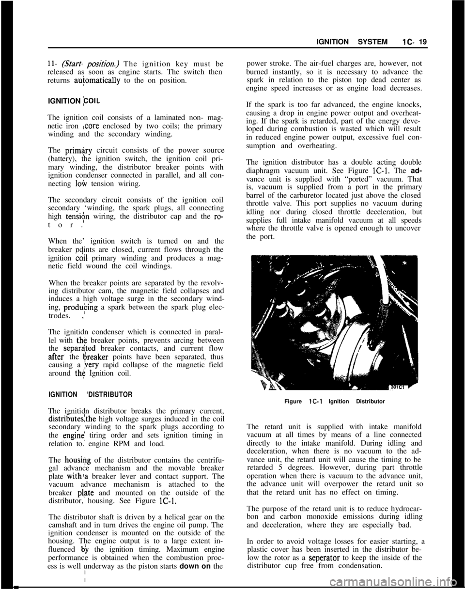
distributor, housing. See Figure lC-1.
The distributor shaft is driven by a helical gear on the
camshaft and in turn drives the engine oil pump. The
ignition condenser is mounted on the outside of the
housing. The engine output is to a large extent in-
fluenced b) the ignition timing. Maximum engine
performance is obtained when the combustion proc-
ess is well underway as the piston starts down on thepower stroke. The air-fuel charges are, however, not
burned instantly, so it is necessary to advance the
spark in relation to the piston top dead center as
engine speed increases or as engine load decreases.
If the spark is too far advanced, the engine knocks,
causing a drop in engine power output and overheat-
ing. If the spark is retarded, part of the energy deve-
loped during combustion is wasted which will result
in reduced engine power output, excessive fuel con-
sumption and overheating.
The ignition distributor has a double acting double
diaphragm vacuum unit. See Figure lC-1. The ad-
vance unit is supplied with “ported” vacuum. That
is, vacuum is supplied from a port in the primary
barrel of the carburetor located just above the closed
throttle valve. This port supplies no vacuum during
idling nor during closed throttle deceleration, but
supplies full intake manifold vacuum at all speeds
where the throttle valve is opened enough to uncover
the port.
Figure lC-1 Ignition Distributor
The retard unit is supplied with intake manifold
vacuum at all times by means of a line connected
directly to the intake manifold. During idling and
deceleration, when there is no vacuum to the ad-
vance unit, the retard unit will cause the timing to be
retarded 5 degrees. However, during part throttle
operation when there is vacuum to the advance unit,
the advance unit will overpower the retard unit so
that the retard unit has no effect on timing.
The purpose of the retard unit is to reduce hydrocar-
bon and carbon monoxide emissions during idling
and deceleration, where they are especially bad.
In order to avoid voltage losses for easier starting, a
plastic cover has been inserted in the distributor be-
low the rotor as a seperator to keep the inside of the
distributor cup free from condensation.
Page 41 of 625
I
ilC- 201973 OPEL SERVICE MANUAL
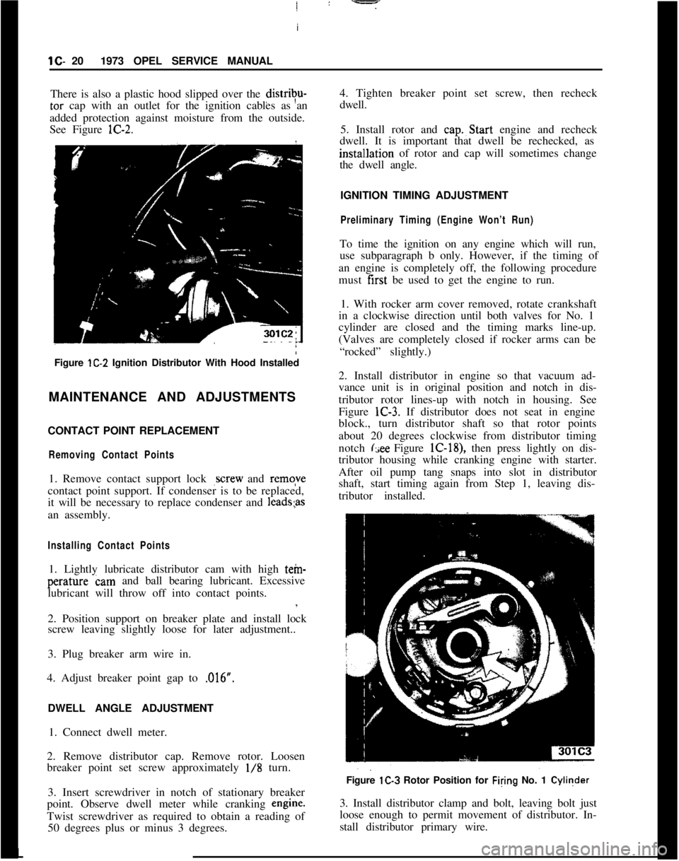
There is also a plastic hood slipped over the distrivu-tar cap with an outlet for the ignition cables as an
added protection against moisture from the outside.
See Figure lC-2.
Figure lC-2 Ignition Distributor With Hood Installed
MAINTENANCE AND ADJUSTMENTS
CONTACT POINT REPLACEMENT
Removing Contact Points1. Remove contact support lock
,screw and remqve
contact point support. If condenser is to be replaced,
it will be necessary to replace condenser and
1eads;asan assembly.
Installing Contact Points1. Lightly lubricate distributor cam with high tein-perature cam and ball bearing lubricant. Excessive
lubricant will throw off into contact points.
:
,
2. Position support on breaker plate and install lock
screw leaving slightly loose for later adjustment..
3. Plug breaker arm wire in.
4. Adjust breaker point gap to ,016”.
/
DWELL ANGLE ADJUSTMENT
1. Connect dwell meter.
2. Remove distributor cap. Remove rotor. Loosen
breaker point set screw approximately
l/8 turn.
3. Insert screwdriver in notch of stationary breaker
point. Observe dwell meter while cranking engine.
Twist screwdriver as required to obtain a reading of
50 degrees plus or minus 3 degrees.4. Tighten breaker point set screw, then recheck
dwell.
5. Install rotor and cap.~Start engine and recheck
dwell. It is important that dwell be rechecked, as
instal~lation of rotor and cap will sometimes change
the dwell angle.
IGNITION TIMING ADJUSTMENT
Preliminary Timing (Engine Won’t Run)To time the ignition on any engine which will run,
use subparagraph b only. However, if the timing of
an engine is completely off, the following procedure
must first be used to get the engine to run.
1. With rocker arm cover removed, rotate crankshaft
in a clockwise direction until both valves for No. 1
cylinder are closed and the timing marks line-up.
(Valves are completely closed if rocker arms can be
“rocked” slightly.)
2. Install distributor in engine so that vacuum ad-
vance unit is in original position and notch in dis-
tributor rotor lines-up with notch in housing. See
Figure lC-3. If distributor does not seat in engine
block., turn distributor shaft so that rotor points
about 20 degrees clockwise from distributor timing
notch
(see Figure lC-18), then press lightly on dis-
tributor housing while cranking engine with starter.
After oil pump tang snaps into slot in distributor
shaft, start timing again from Step 1, leaving dis-
tributor installed.
Figure lC-3 Rotor Position for Filing No. 1 Cyliqder
3. Install distributor clamp and bolt, leaving bolt just
loose enough to permit movement of distributor. In-
stall distributor primary wire.L
Page 42 of 625
IGNITION SYSTEMlC-214. Rota&distributor counterclockwise slightly until
contact pbints just start to open. This must be done
very carefully or engine will not start.
5. Install distributor cap. Make sure spark plug wires
are correctly installed in distributor cap, through clip
and on spark plugs.
Finish TimingIContact boint gap
(.016” at widest gap) or dwell 50
degrees plus or minus 3 degrees should always be
checked before adjusting ignition timing.
1. Connekt timing light to No. 1 spark plug.
2. Disconnect and plug vacuum advance unit and
retard u$it hoses.
3. Connect a tachometer from distributor side of coil
to
groun$l.4. Start dngine. Set idle speed to 900 RPM.
5. Rotate distributor as necessary to align timing
marks. T;ming mark is a steel ball embedded in the
flywheel and a pointer in a window in the right fly-
wheel housing. See Figure lC-4.:Figure lC-4 Ignition Timing Marks
6.
Tightq clamp bolt securely and recheck timing
mark ahgnment.
7. Reconnect vacuum hoses and adjust engine idle
speed
an: mixture.
IGNlTlOFj WIRE INSPECTION
1. The c$il and spark plug wires are of a specialresistance type. These secondary ignition wires
reduce television and radio interference.
2. Wipe ignition wires with a cloth moistened with
solvent and wipe dry. Bend wires to check for brittle,
cracked or swollen insulation. Defective insulation
will permit missing or cross-firing of spark plugs,
therefore any defective wires must be replaced.
3. If wire insulation is in good condition, clean any
terminals that are corroded and replace any termi-
nals that are broken or damaged. Terminals must tit
tight on spark plugs and in distributor cap.
4. Replace any hardened, cracked or loose cap nip-
ples or spark plug boots.
5. Check resistance of each wire from contact inside
distributor cap to spark plug or coil terminal. Re-
place any wire having over 10,000 ohms resistance
reading. See Figure lC-5.
Figure fC-5 Checking Ignition Wire Resistance
CHECK IGNITION OUTPUT
1. Disconnect secondary coil ivire so that engine will
not start. Connect a voltmeter from the battery side
of the coil primary to ground and check voltage
while engine is cranking. Reading should be 10 volts
or more. Low reading could be caused by a defective
battery, a discharged battery, high starter current
draw, a bad connection in the starter circuit or a bad
connection in the primary ignition circuit.
2. Connect an oscilloscope according to manufac-
turer’s instructions. Disconnect coil wire. Crank en-
gine and read coil output voltage. Reading should
exceed 20 KV (20,000 volts).